Scalable Computing: Practice and Experience
Volume 15, Number 2, pp. 169–185. http://www.scpe.org
ISSN 1895-1767 c
⃝2014 SCPE
REGULATED CONDITION-EVENT MATRICES FOR CLOUD ENVIRONMENTS
RICHARD M. WALLACE1
, PATRICK MARTIN2
, AND JOS´E LUIS V ´AZQUEZ-POLETTI3
Abstract. Distributed event-based systems (DEBS) are networks of computing devices. These systems have been successfully implemented by commercial vendors. Cloud applications depend on message passing and inter-connectivity methods exchanging data and performing inter-process communication. Both DEBS and Clouds need time-coordinated methods of control not depen-dent on a single time domain. While DEBS have specific implementation languages for complex events, Cloud systems do not. Clouds and DEBS have not yet presented an explicit separation of temporally based event processing from computations. Using a regulated, isomorphic, temporal architecture (RITA), a specific language and separation of temporal event processing from process-ing computation is achieved. RITA provides a functional programmprocess-ing style for developers usprocess-ing familiar language constructs for integration with existing processing code without forcing the developer to work in multiple coding paradigms requiring extensive “glue code” allowing coding paradigms to work together. This paper introduces RITA as a guarded condition-event system that has explicit separation of event processing and computation with constructs allowing integration of time-aware events for multiple time domains found in Cloud or existing distributed computing systems.
Key words: Cloud; Distributed networks; Distributed applications; Data Abstraction; Complex Event Processing; Condition-event Matrix, DEBS, Event Model
AMS subject classifications. 68M14, 68M20, 68N19
1. Introduction. RITA is an event processing architecture initially developed as a proprietary product in the telecommunications industry between 1998 and 2000 [29] allowing federated and distributed systems to communicate without undue interruption of intensive computing applications. An open source implementation for RITA is being developed by the authors of this paper. This paper precedes the release of this code base to introduce RITA concepts and facilitate understanding of RITA concepts.
The roots of RITA came from real-time avionics control software [30, 16] and with the current move to have cloud systems handle time critical processing, so RITA is now relevant to cloud systems. These cloud systems have reached a processor interconnect scale requiring carefully controlled intra- and inter-processor communication just as avionics and telecommunications systems require [2]. RITA focuses on the real-time processing and optimal communication needs of intensive computing applications by controlling time-aware and data value sensitive guards to prevent unnecessary interruption thus allowing more CPU time for intensive computing applications. We will show that RITA is a novel service for high performance computing applications that have migrated to cloud environments.
RITA is designed for event based, quantitative, time critical communication for computationally intensive applications which include communication networks, modeling and simulation, financial forecasting and trading systems, computational chemistry, and drug discovery as obvious applications. RITA can also be applied to workflow systems that are instance-intensive. These systems are unlike computationally intensive systems as they have thousand of instances per second of concurrent, often relatively simple, workflow instances.
RITA is a novel minimal set of canonical event transform types that are formally defined. These transform types are used for specification of ´a priori time and data values relevant to event-based data transformations. RITA is a compact event system where its elements are used in combination to build larger event processing systems. Thus, by establishing a condition-event matrix control for a DEBS, it is possible to have data controls written in a functional programming form and express the imperative form as a separate control structure. The C language is used in RITA due to its high degree of familiarity by developers.
During RITA development JMS [5] was just being written and CORBA [18], IBM MQ [12], TIBCO Ren-dezvous [27], BEA Tuxedo [21] (now owned by Oracle Corp.), and other message oriented middleware products were in their initial stages of use. Over time these and other DEBS have matured and have become general purpose messaging systems with the majority of their messaging development focused on publish and subscribe
1
Universidad Complutense de Madrid, Spain,[email protected] 2
Queen’s University, Kingston, Ontario, Canada,[email protected] 3
Universidad Complutense de Madrid, Spain,[email protected]. The authors would like to thank the ServiceCloud project (MINECO TIN2012-31518).
semantics. This has been well understood and codified by the Object Management Group over the ensuing years [19]. RITA does not use CORBA semantics, is agnostic to inter-process communication (IPC) and data transport methods, and does not prescribe a specific interface thus allowing it to be compatible with commu-nication products and techniques such as activeMQ, Websphere MQ, shared memory, sockets, OpenMPI, and others.
The structure of the paper starts with an informal description of the event model types in §2 followed by the formal semantics described in §3 which is a foundation for the condition-event matrix described in §4, the explicit time components in §5, an example RITA structure in§6, relevancy to cloud computing in§7, related work in §8, and concluding with future work in§9. The paper defines event originators, the event model, and event processing as per the reference model discussion in [22].
2. Event Model. The RITA event model is based on a set of canonical state transformations that can be combined to create complex event interactions. The three canonical types are “spike,” “set-at,” and “tran-sitional” which are informally defined in the following subsections. Time is shown astand event state is shown as σ.
Each type occurs over a ∆tfor the event space time-frame in which it occurs. Time is infinitely divisible, countable, and continuously and monotonically increasing, thus any incremental units of measurement are only sample points of infinitely countable time. This definition provides for any discussion of an event “lifetime.” Any perceived event lifetime is defined by the latency of its occurrence and its subsequent observance. This latency is graphically shown in Figures 2.1, 2.2, and 2.3 showing the canonical types state change using electrical square-wave graphics. The slope shown in these figures is a named state change (σn →σn±1) of an event and this illustrates that a state change has an interval of time in which its state is not known while time continues to increment, albeit by an infinitesimal amount, during a state change. Event sequencing requires that there be a sufficient lifetime so that a sequence of events can create a queue. If an event has an insufficient lifetime, or if the next event arrival overwrites the current event, then no queuing can occur. Lifetimes are detailed for each event type in the following subsections.
The remainder of this section builds the logical foundation of event semantics by describing the temporal mechanics of the canonical event types. This is then further detailed in§3 where each type is formally described, cumulatively producing a basis for the RITA notation shown in§6 which is enforced in the runtime environment by following these formally defined event types and temporal specifications. This formalism is the core of the RITA concept. We believe RITA to be an advancement to the current state of the art for distributed, federated cloud applications through use of the condition-event matrix detailed in§4.
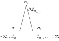
2.1. Spike Event. The spike event graphic in Figure 2.1 occurs at a ∆t asymptotic to zero. Figure 2.1 has prior time shown as time in the past until event execution, −∞ · · ·tn, where tn is the “now” time of the event occurring that causes state change fromσ1toσ2for a subdivision of timetnshown as ∆tn0..1. At the end
of this asymptotic to zero time, the state changes back to the original σ1 state for time tn+1· · · ∞. Events of this type are considered periodic “heartbeat” events. This event type can be used for counted threshold limits, keep-alive notification, or request for service. This event type can not be queued and has no lifetime.
-
∞
...
t
nt
n+1…
+
∞
s1s2
s1
Dt
n 0..1Fig. 2.1.“Spike” Event. Vertical axis is state (axis omitted)
events such as system initialization and system termination. As shown in Figure 2.2, this is not the transitional event type as there is no ability for a transition from state σn to return after transitioning to stateσn±1. This event type has an infinite lifetime and can be queued.
OR
-
∞
...
t
nt
n+1…
+
∞
-∞
...
t
nt
n+1…
+
∞
s1
s2 s1
s2
Fig. 2.2.“Set-At” Event. Vertical axis is state (axis omitted)
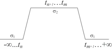
It is important to discuss the difference between a set-at event and a transitional event. While the wave forms used to illustrate the canonical events may appear the same as shown in Figures 2.2 and 2.3, note the definite differences in the time elementt where, as is explained in Subsection 2.2, aset-at event can transition only once during the lifetime of the system; whereas a transitional event can oscillate between statesσ1 and σ2 at any frequency greater than one. This temporal difference is very important in constructing a system of events without ambiguity as to the semantics of the intent of a state change.
2.3. Transitional. The transitional event graphic in Figure 2.3 occurs over some period of measurable time with an event-sensitive entity perceiving a state change which separates this event type from the “spike” event type. Past and future time is as described in§2.1. This event type is semantically dense as each increment of time can result in a different state. The semantic meaning is compounded based on the frequency of state change and for how many sampling intervals of t the state remains constant. This event type has a limited lifetime, albeit the transition between σ1 →σ2 →σ1 can be as long as the system needs it to be, thus is can appear as a set-at event type, but it is not because it can revert while set-at can not revert to its σ1 state. Queuing of this event type requires prioritized time-based queuing that can be dynamically edited as higher priority events occur or as queued events expire or both.
-
∞
...
t
nt
n+1…
t
mt
m+1…
+
∞
s1
s2
s1
Fig. 2.3. Transitional Event. Vertical axis is state (axis omitted)
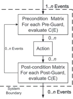
2.4. Event Type Use. Using these event types, RITA processes events as shown in Figure 2.4. Given one or more eventsE, conditionsC, guardsG, and actionsA, the system has 1· · ·ninputs to a precondition-event matrix evaluating events against specific guards. Guards are a proper subset of conditions (G ∈ C). If the guard evaluates to True, the action step comprised of 1· · ·n conditions on that event, C1(E). . . Ck(E), are evaluated. The results of the action step are 0· · ·noutputs, based on the evaluation of condition vectors, to a post-condition event matrix. If the post-condition event guard matrix evaluates to True, the output action data – now seen as input event data – is input to another precondition-event guard matrix. In actual use, the definition of guards for precondition and post-condition matrices are compressed in the event evaluation chains so that the trace,
Gpre(E)→A→Gpost(E)→ Gpre(E)→A→Gpost(E)· · ·
has the post-condition guard being the precondition for the next action step:
Gpre→A→Gpostpre→A→Gpostpre· · · (2.2)
As shown in transition chain 2.2 each event system can be chained to other event systems.
Precondition Matrix For each Pre-Guard,
evaluate C(E)
Action
Post-condition Matrix For each Post-Guard,
evaluate C(E)
0..nEvents 1..nEvents
Precondition Matrix For each Pre-Guard,
evaluate C(E)
Action
Post-condition Matrix For each Post-Guard,
evaluate C(E)
0..nEvents 1..nEvents
0..nEvents
0..n
0..n
System Boundary
Fig. 2.4.Event Processing
3. Formal Event Model. Building on the informal description given in §2, a definition for the formal event specifications and formal condition-event matrix is given. For each of the three event forms (i.e. types) the formal definition of the precondition and post-condition are formally defined. The action step, as shown in transition chain 2.2 above, is not formally defined. The precondition allows an event to initiate an action step (calculation of application data) in the system. A post-condition dampens output from the action step by suppressing output that does not evaluate to T rue in the post-condition. Only post-conditions create new events, or propagation of existing events, in the system. Guards and conditions evaluate specified application data as being time, summation, or delta critical.
Time critical information is data which must reach the computational process at fixed times usually ex-pressed as some delta time. Summation critical information is data that is summed to form a value that triggers an event. Delta critical information is data that must be significantly different from its previous value in order to trigger an event.
3.1. Spike Event. The spike event form has the precondition specification of:
∃E:∀Cpre(E)→T rue (3.1)
There exists an event such that a precondition on the event will evaluate toTrue. The spike event form has the post-condition specification of:
∃E:∀Cpre(E)→T rue∴ ∃A(E)⇒ ∃E′∋Cpost(E
′
)→T rue (3.2)
Proposition 3.2 asserts the precondition and then states therefore there exits an action for the event implying that there exists some output eventE′
such that the post-conditionCpost evaluates toT rue.
3.2. Set-At Event. The set-at event form has the precondition specifications based on an initial condition value:
∃E:∀C(E)(−∞...tn−1)≡F alse;
∃Atn(E) :Cpre(E)→T rue⟨∀∆t⟩
There exists an event where, under all conditions,E results in F alse. At some timetn there exists an action, A, where the precondition for the event results inT rueover the sequence of all increments of time. Temporally, using basic propositional linear temporal logic [15], this is:
[P(E)⇒P(E′)] (3.4)
This states that there is always an implication ofP(E) toP(E′
) for all predicates ofE andE′ .
The set-at event is a terminal state transition. This means that once the set-at event form has happened, it is an individuate action and the post-condition is NULLas an external source to the entire system is required to change the state once the event occurs to transform the set-at event state.
3.3. Transitional Event. The transitional event form has the precondition specification of:
∃E:Cpre(E)→T rue⟨∆t1· · ·∆tn⟩ ∈ ∀∆t) (3.5)
There exists an event where the precondition results in T rue for a subset of all time. The post-condition is specified as:
∃Cpre(E)→T rue∴{∃A(E)|T rue⟨∀∆tt1...tn⟩}
⇒ ∃E′
∋Cpost(E ′
)→T rue (3.6)
There exists a precondition on an event evaluating to T rue; therefore there exists an action for the event such that it is T ruecomprehended over a sequence of time implying that there exists an output event for the post-condition that evaluates toT rue.
4. Condition-Event Matrix. The RITA condition-event matrix is comprised of a system of three ma-trices that are evaluated by row; expressed as:
G1 .. . Gn
•
C1(E1)· · ·Ck(E1) ..
.
Cn(En)· · ·Cn,k(En)
•
op1,1· · ·op1,k−1 .. . opn,1· · ·opn,k−1
→
R1 .. . Rn
(4.1)
Given trace 2.2, the chaining of systems of condition-event matrices requires that guards be part of preconditions only. As shown in Equation 4.1, a vector,V, is defined asV: (Cn(En)· · ·Ck(En)), a “row.” The condition vector is comprehended, post guard evaluation at a single timet, across the condition resultants with the operators∧ “and,”∨“or,”⊕“xor,” and¬“not” is expressed as:
C1(E1)op1C2(E1)op2C3(E1)· · ·opk−1Ck(E1) (4.2)
The resultant vector,R, ifT rueindicates that the output eventE′ be propagated to the vector of guards in the next condition-event matrix. The separation of logical control occurs using the Gn, Cn, andopn components. Internal toCncomponents is where data control dispatch calls occur to application code. If a condition position is empty in the matrix the postfix opn is considered NULL. Thus a row may may be sparsely populated and the emptyCn and NULLopn,k allows for sparse condition vectors as these matrix elements do not have to be evaluated.
5. Explicit Time. All guard and condition expressions for RITA have time expressed in delta or sum-mation time. Currently these expressions use a restricted subset of C language syntax due to its familiarity with developers. Allowed constructs areIF-THEN-ELSE,SWITCH where alternatives must be inclusive of all values passed by the Guard condition, relational operators, no pointers or locally declared storage is allowed, and only boolean stack values are allowed as return values with the required form: <condition name>TRUE or <condition name>FALSE. As the<condition name>is known to the system, the post-fixTRUE orFALSE is a name decoration that RITA enforces.
Guard or Condition code. Its function signature is: int evaluate time(<vector variable>,[BEFORE | AFTER | NOW], <delta>). The additional functionscreate time(), andget time() are only used in application code external to the event engine. The event engine system time is uniform throughout evaluation of the guard and its condition vector for a specific RITA system. Time domains can, and do, vary across instances of RITA systems. RITA handles these variant time domains by design.
Real-time implementations need fine-grain time evaluation. For the event engineevaluate time() function, comparison of vector variables of time type use the highest precision time for the computer architecture exe-cuting it. Special timing access is needed beyond the default programming API to the system time function. Since 2005 high precision time such as the High Precision Event Timer (HPET) hardware timer used in Intel chip sets [14] and, since 2013, nanosecond time resolution with the HPET library is available [7]. Within a cloud environment, systems may also rely on precision hardware timers like those available from Symetricom (http://www.symmetricom.com).
The resultant of the evaluate time()function isTRUE or FALSE. The special enumeration values of BE-FORE,AFTER, andNOWare used to determine the comparison of the system time with the vector variable time. TheNOWenumeration must have a decimal delta of zero. The delta value is a numerical constant that is a positive floating point value with the precision needed and supported by the system hardware timer.
Theget time()function is used to examine the time value set in thecreate time() function. Assignments to vector variables are allowed. Vector variables can be used in multiple event matrices. Chaining of event matrices ensures that the event value is modified in a deterministic method, without race conditions, and that the tuple of {event, value} is propagated through-out the system of condition-event matrices resulting in a final event consumption. If a user causes race conditions by having multiple matrices modify a vector variable in parallel, the pre-processor will alert the user. These restrictions ensure that each condition-event matrix executes in the same sequence given the same event sequences and event values.
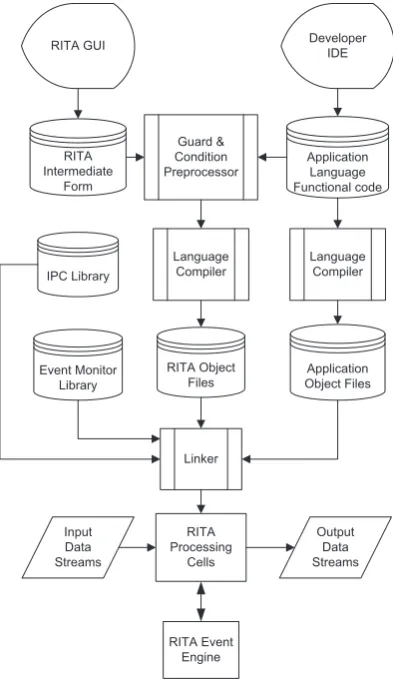
6. Putting the Parts Together. The preceding sections have described the RITA event system and the mechanics of the system. A brief code fragment showing the structure of the RITA system description notation is presented in order to link the event formalism in§2 and§3 to code which is the specification notation created by the pre-processor as shown in Figure 6.1 where the RITA specification is parsed by the Guard and Condition pre-processor into a compiled language. The application, RITA translated code, and specific libraries are then compiled and linked into one image. While this may appear to be a a monolithic implementation, it is not as each RITA system can be matched to a application program function and thus, at the most granular level, one has independent communicating processes ´a la Communicating Sequential Processes by Hoare [11].
In Listing 3 the elements of a RITA system, guard, vector, and resultant are seen. These elements are described for each line in Listing 3:
• Lines 1-2: Linkage to application code functions that can run as detached processes.
• Lines 6-9: Declaration of events and variables for TEST SYSTEM 1. Note the two events that have a named canonical event form, and their data type as an event occurrence has data associated with it. • Lines 11-25: Declaration of conditions. Note that INITIAL CHECK contains an application call to
user function 1 that runs as a detached process whileuser function 2 is a blocking call forFLOW. The latter, while allowed, is not a preferred method of invoking application code.
• Lines 27-37: Declaration of guards. As G∈ C, these look very much like conditions as they should. The primary usage is to short-circuit the evaluation of conditions in a vector. As such these are very simple gating controls.
• Lines 40-52: Declaration of vectors. Note the order of guard, condition(s), and result as these are the implementation of the condition event matrix. The boolean operation attached to each condition matches the opn in the condition event matrix. There may be no result from an evaluation. See the null condition for VECTOR 2 at line 49. Note the output fromVECTOR 1 isSystemOn andnull in VECTOR 2. These two events stimulate further action in the RITA system.
• Lines 59-104: This is the second system in the RITA event system configuration. VectorSystem2 Looper has the event Update propagating a new value of the event. The constructs inTEST SYSTEM 2 are like TEST SYSTEM 1 and their descriptions are not repeated.
detached process. The symbol “<-” is read as “Assign output from the right-hand system, or event, to the left hand system.” Note that multiple right-hand systems may be specified as input to a left-hand system using this notation: “system1 <- system2, system3” as an example. This notation is similar to concurrent signal assignment statements in VHDL [13].
RITA GUI
Guard & Condition Preprocessor
Application Language Functional code
Developer IDE
Language Compiler RITA
Intermediate Form
Application Object Files Event Monitor
Library
Language Compiler
Linker RITA Object
Files IPC Library
Input Data Streams
Output Data Streams RITA
Processing Cells
RITA Event Engine
Fig. 6.1.RITA Infrastructure.
Listing 3
RITA Code Fragment
1 with " ../ a p p l i c a t i o n / u s e r _ a p p . hpp " ;
2 use " u s e r _ f u n c t i o n _ 1 " , " u s e r _ f u n c t i o n _ 2 " ;
3
4 system T E S T _ S Y S T E M _ 1
5 {
6 event ( trans , bool ) : S y s t e m V a l u e 1 ( false ) ;
7 int4 : R e q u e s t s (0) ;
8 time : F l o w D u r a t i o n ( " 500 ms " ) ;
9 float8 : F l o w R a t e (0.0) ;
10
11 c o n d i t i o n I N I T I A L _ C H E C K {
12 if ( S y s t e m O n == true ) {
14 return I N I T I A L _ C H E C K _ T R U E ;
15 }
16 return I N I T I A L _ C H E C K _ F A L S E ;
17 } // I N I T I A L _ C H E C K
18
19 c o n d i t i o n FLOW {
20 Fl o w R a t e = u s e r _ f u n c t i o n _ 2 ( F l o w D u r a t i o n ) ;
21 if ( F l o w R a t e < 5 ) {
22 return F L O W _ T R U E ; }
23 else {
24 return F L O W _ F A L S E ; }
25 } // FLOW
26
27 guard S y s t e m O n {
28 if ( ! S y s t e m O n ) { break V E C T O R _ 1 ; }
29 return S y s t e m O n _ T R U E ;
30 } // S y s t e m O n
31
32 guard Update {
33 if ( Update <= 10 ) {
34 return U p d a t e _ T R U E ;
35 }
36 return U p d a t e _ F A L S E ;
37 }
38
39 // S y s t e m O n is true at start . Vector will a c t i v a t e .
40 vector V E C T O R _ 1 {
41 guard : S y s t e m O n ;
42 c o n d i t i o n ( and ) : I N I T I A L _ C H E C K ;
43 c o n d i t i o n ( or ) : FLOW ;
44 result : S y s t e m O n 1 ( true ) ;
45 } // V E C T O R _ 1
46
47 vector V E C T O R _ 2 {
48 guard : Update ;
49 c o n d i t i o n ( and ) : null ;
50 c o n d i t i o n ( or ) : I N I T I A L _ C H E C K ;
51 result : C h e c k E v e n t s ( true ) ;
52 } // V E C T O R _ 2
53
54 } // T E S T _ S Y S T E M _ 1
55
56 // ++
57 // T E S T _ S Y S T E M _ 2
58 //
--59 system T E S T _ S Y S T E M _ 2
60 {
61 int2 : u p d a t e _ v a l u e (0) ;
62 int2 : t m p _ u p d a t e (0) ;
63 int2 : R e q u e s t s (0) ;
64
65 c o n d i t i o n S e t U p C h e c k E v e n t s {
66 if ( u p d a t e _ v a l u e <= 10 ) {
67 t m p _ u p d a t e = u p d a t e _ v a l u e + 6;
68 }
70 return S e t U p C h e c k E v e n t s _ T R U E ;
71 }
72
73 c o n d i t i o n A d d U p d a t e {
74 u p d a t e _ v a l u e = u p d a t e _ v a l u e + 1;
75 return A d d U p d a t e _ T R U E ;
76 }
77
78 guard S y s t e m O n 1 {
79 if ( S y s t e m O n 1 == true ) {
80 return S y s t e m O n _ T R U E ; }
81 else {
82 break S T A R T _ C h e c k E v e n t s ;}
83 }
84
85 guard C h e c k E v e n t s {
86 if ( R e q u e s t s < 10) {
87 R e q u e s t s = R e q u e s t s + 1;
88 return C h e c k E v e n t s _ T R U E ;
89 }
90 return C h e c k E v e n t s _ F A L S E ;
91 } // C h e c k E v e n t s
92
93 vector S T A R T _ C h e c k E v e n t s {
94 guard : S y s t e m O n 1 ;
95 c o n d i t i o n ( and ) : S e t U p C h e c k E v e n t s ;
96 result : Update ( t m p _ u p d a t e ) ;
97 }
98
99 vector S y s t e m 2 _ L o o p e r {
100 guard : C h e c k E v e n t s ;
101 c o n d i t i o n ( and ) : A d d U p d a t e ;
102 result : Update ( u p d a t e _ v a l u e + 1) ;
103 }
104 } // T E S T _ S Y S T E M _ 2
105
106 control {
107 event ( setat , bool ) : S y s t e m O n ( false ) ;
108 event ( setat , bool ) : S y s t e m O n 1 ( false ) ;
109 event ( spike , int4 ) : C h e c k E v e n t s (0) ;
110 event ( trans , int4 ) : Update (0) ;
111
112 begin
113 T E S T _ S Y S T E M _ 1 <- S y s t e m O n ( true ) ;
114 T E S T _ S Y S T E M _ 2 <- T E S T _ S Y S T E M _ 1 ;
115 T E S T _ S Y S T E M _ 1 <- T E S T _ S Y S T E M _ 2 ;
116 end
117 }
The listing demonstrates the usage of each canonical event form, the condition event matrix elements (Guards, Vectors, Operators, andResultants) from Equation 4.1. RITA specifications are converted into exe-cutable code via the development procedure shown in Figure 6.1. This code is compiled with the application and becomes the event control mechanism benefiting overall throughput of the system.
conditions andresults anullstatement can be used. Using null in acondition clause acts as a placeholder and the condition becomes a non-operation for vector evaluation. Using null in a result clause indicates that the vector has no output event which is useful when a vector needs to terminate event propagation or a vector is only activated to start concurrent/in parallel calls to user functions.
7. Cloud Computing. Cloud systems can be separated into four major layers: IaaS: Infrastructure as a Service — physical/virtual machines and hypervisor NaaS: Network as a Service — network/transport services between systems
SaaS: Software as a Service — access to application software and databases PaaS: Platform as a Service — IaaS, base O/S, run time services, and NaaS
RITA is a run time service in the PaaS layer. The advantages of a RITA in the PaaS layer are:
• Preventing application unbounded priority inversion by reducing the communication interrupts that lead to this problem.
• As an event propagator it is designed for partitioned, communicating processes in a “share all,” “shared partial,” or a “shared nothing” environment supporting parallelism without heavy use of synchronization primitives for publication/subscription (pub/sub) systems or message passing interfaces.
• High performance worker threads for “scatter gather” configurations can use the RITA bifurcation of communication and computation to improve performance with a high performance PaaS IPC.
• Canonical event forms define the data communication needed for a distributed application making all communication explicit and drastically reducing communication traffic loads and errors.
Cloud computing has processes executing autonomously and independently communicating with each other. This communication can quickly increase to a level that decreases system throughput. As mentioned in §1, detailed in §8, communication currently in use depends on uniform, monolithic communication mechanisms following a pub/sub methodology for tight-cluster, grid, or single systems. These systems are dependent on a single homogeneous time domain that requires an inordinate amount of effort handling latency issues in a monolithic time domain for federated, distributed cloud systems. This latency can cause side-effects due to imperative code managing events. Events are either missed and must be resent, if possible, or the imperative code induces more latency by direct queue management from the application code.
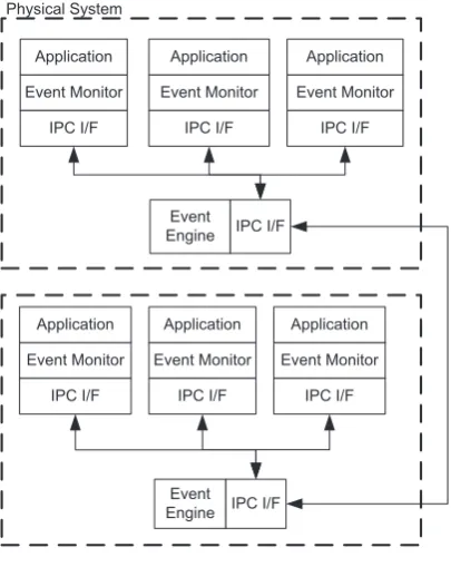
Declarative coding in RITA allows side-effect free conditions that are separate from the imperative applica-tion code. Using RITA it is possible create a series of processes that can be (a) event sensitive by using only the canonical event forms (i.e., spike, set-at, and transitional), (b) temporally sensitive, based on local time domain and triggered by canonical events, and (c) value sensitive through delta value comparisons. This results in each RITA cell being semi-autonomous so unexpected behavior can either be ignored or can trigger a recovery in RITA processing cells as required. RITA is designed to work in a distributed and autonomous environment. A discussion of cloud computing and its dependencies on networks [1] observes that the issues of network traffic are becoming limiting factors in cloud computing systems. RITA can reduce unnecessary IPC traffic and so improve application performance as described in [30] and [29]. Other DEBS do not have the clean demarcation between the declarative and imperative portions of an application and the ability to naturally enforce functional programming in a non-functional specific language which is why Lisp, Scheme, and Haskell have never really surpassed C, C++, Java, and other imperative languages in commercial popularity. RITA processing stacks shown in Figure 7.1 give an example of how separate physical systems can have multiple RITA systems (i.e. a processing stack) mapped and how each system communicates with each other via an IPC interface and event engine that enforces event form semantics.
Event Engine
Event Engine Event Monitor
Application
IPC I/F
Event Monitor Application
IPC I/F
Event Monitor Application
IPC I/F
Event Monitor Application
IPC I/F
Event Monitor Application
IPC I/F
Event Monitor Application
IPC I/F IPC I/F
IPC I/F Physical System
Fig. 7.1.Multiple RITA Systems
or separate computing machine. Common distributed systems operate in this fashion but RITA is the only one that prevents unnecessary IPC from reaching computationally or instance-intensive applications.
Figures 7.2 to 7.9 present data collected for an application controlled IPC and a RITA controlled IPC for the Mass Markets Billing and SHERIFF (Statistical Heuristic Engine to Reliably and Intelligently Fight Fraud) systems which was a joint venture between MCI and British Telecom [23]. This heterogeneous grid implementation was comprised of multiple IBM/VM LPARs, an multi-node VAXCluster, and multiple IBM/AIX HACMP RS/6000s. The figures show the beneficial result of using RITA. RITA reduces the decision logic processing time needed by application code.
0.0001
0.001
0.01
0.1
1
10 0
5000 10000 15000 20000 25000
0 1 2 3 4 5 6 7 8 9 10 11 12 13 14 15 16 17 18 19 20 21
%
T
im
e
C
o
m
D
e
ci
si
o
n
Lo
g
ic
R
T
Ms
g
s/
S
e
c
Clients
RoundtripMsgs/sec %TimeinCommDecisionLogic
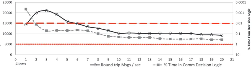
Fig. 7.2.Local client, Non-RITA, Non-Persistent.
Operational requirements set by the MCI and BT corporations for these systems were 100% data integrity and 100% data delivery for all message payloads with ACID1 guarantees for both in memory or persistent message data forms. For transient data, “eventually consistent” BASE2 semantics were required for system
1
Atomicity, Consistency, Isolation, Durability 2
0.0001 0.001 0.01 0.1 1 10 0 5000 10000 15000 20000 25000
0 1 2 3 4 5 6 7 8 9 10 11 12 13 14 15 16 17 18 19 20 21
% T im e C o m D e ci si o n Lo g ic R T M sg s/ S e c Clients
RoundtripMsgs/sec %TimeinCommDecisionLogic
Fig. 7.3.Local client, RITA enabled, Non-Persistent.
0.001 0.01 0.1 1 10 0 500 1000 1500 2000 2500 3000 3500 4000 4500 5000
0 1 2 3 4 5 6 7 8 9 10 11 12 13 14 15 16 17 18 19 20 21
% T im e C o m De ci si o n Lo g ic R T M sg s/ S e c
Clients RoundtripMsgs/sec %TimeinCommDecisionLogic
Fig. 7.4.Local client, Non-RITA, Persistent.
0.001 0.01 0.1 1 10 0 500 1000 1500 2000 2500 3000 3500 4000 4500 5000
0 1 2 3 4 5 6 7 8 9 10 11 12 13 14 15 16 17 18 19 20 21
% T im e C o m D e ci si o n Lo g ic R T M sg s/ S e c Clients
RoundtripMsgs/sec %TimeinCommDecisionLogic
Fig. 7.5.Local client, RITA enabled, Persistent.
informational messages, logging, or diagnostic messages. Tests used MQSeries 5.2 local client in-memory queues and server channel queues. Local client and server channel experiments were run with and without RITA, and with and without persistence. Test were run 1,000 times and averaged.
Results show an 80% time reduction in communication decision logic processing thus applications had less probability of context switch thrashing. The increase in the number of messages per second produced by RITA shows that the IPC subsystem had less application interrupt. RITA did have some effect in improving round-trip message volumes but, while significant, it was considered a beneficial side-effect as round-round-trip performance is determined by network congestion and IPC buffering and queuing and not directly controlled by RITA.
0.0001 0.001 0.01 0.1 1 10 0 100 200 300 400 500 600
0 1 2 3 4 5 6 7 8 9 10 11 12 13 14 15 16 17 18 19 20 21
% T im e C o m D e ci si o n Lo g ic R T M sg s/ S e c Clients
RoundtripMsgs/sec %TimeinCommDecisionLogic
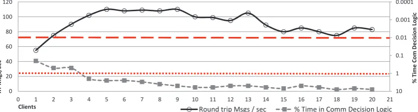
Fig. 7.6. Server Channel, Two Servers, Non-RITA enabled, Non-Persistent.
0.0001 0.001 0.01 0.1 1 10 0 100 200 300 400 500 600
0 1 2 3 4 5 6 7 8 9 10 11 12 13 14 15 16 17 18 19 20 21
% T im e C o m D e ci si o n Lo g ic R T M sg s/ S e c Clients
RoundtripMsgs/sec %TimeinCommDecisionLogic
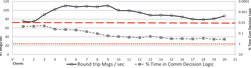
Fig. 7.7. Server Channel, Two Servers, RITA enabled, Non-Persistent.
0.0001 0.001 0.01 0.1 1 10 0 20 40 60 80 100 120
0 1 2 3 4 5 6 7 8 9 10 11 12 13 14 15 16 17 18 19 20 21
% T im e C o m D e ci si o n Lo g ic R T M sg s/ S e c Clients
RoundtripMsgs/sec %TimeinCommDecisionLogic
Fig. 7.8. Server Channel, Two Servers, Non-RITA enabled, Persistent.
constant at 262,144 bytes. Non-persistent messages were in memory without disk I/O. Persistent messages were written to disk using the MQ logging capability.
Each measurement graph has two vertical axes. The left axis shows the messages per second with values increasing vertically. The right axis shows the percent of time spent by the applications in communication decision logic — determining if the IPC is of significance to the calculations — with the values decreasing vertically. The red lines are the control chart values for operational limits for round-trip communication time (1.0 to 0.01 second).
7.2. Cloud PaaS with RITA. From hundreds of PaaS systems [8] [9] there are several open source systems consistently described as some of best systems to use. The PaaS systems listed are:
0.0001
0.001
0.01
0.1
1
10 0
20 40 60 80 100 120
0 1 2 3 4 5 6 7 8 9 10 11 12 13 14 15 16 17 18 19 20 21
%
T
im
e
C
o
m
D
e
ci
si
o
n
Lo
g
ic
R
T
M
sg
s/
S
e
c
Clients
RoundtripMsgs/sec %TimeinCommDecisionLogic
Fig. 7.9. Server Channel, Two Servers, RITA enabled, Persistent.
• Cloud Foundary & BOSH (http://www.cloudfoundry.com) • OpenShift (http://openshift.github.io)
We have choosen OpenShift OriginTMas the PaaS framework. OpenShift Origin/OpenStack terminology is unique to this product. Table 7.1 provides the terminology translation.
Table 7.1
OpenShift terminology translation to normal terminology
OpenShift Term Translation to Normal Terminology
Broker Host manager, controls nodes; typically a VM
Cartridge A technology stack or framework (PHP, Perl, JEE, Python, MySQL, et.al.) to build
applications
Plugin system utilities used with a kernel;authconfig, DNS, et.al.
Gear Allocation of memory, compute, and storage resources to run applications
Node A computer; single-board, blade, et.al. Usually has only local storage for the kernel Application Instantiation of a cartridge (over-loaded term). Differentiated from a nominal cartridge
in that a user has written additional application code that uses cartridges
Scaled App Application instantiated in multiple gears
For OpenShift Origin, a “Gear” is a shell on a node in a shared-nothing instance of the OpenStack IaaS. The usage is to “spin-up” another “Gear” when more instances are created by the OpenShift load balance utility, HA-Proxy. Gears are run as a node O/S on VMs. A “Cartridge” is a software component that is directly used in a gear. Utilities, development tools, and database systems can be Cartridges. A Cartridge uses a specific directory template allowing it to be installed on the Gears.
Initial communication establishing a Gear in OpenStack Origin is done viasshto the Broker which config-ures the nodes. The Broker manages multiple nodes, with each node supporting a host operating system [24]. The details of OpenShift Origin management is available from the product guides at http://openshift.git-hub.io/.
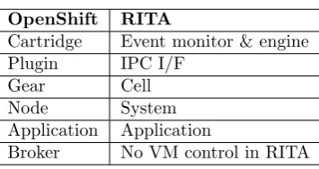
Using the OpenShift Origin terms, the mapping of the RITA infrastructure to OpenShift is shown in Table 7.2. While there is no VM support in RITA, it can be deployed as a Cartridge in an OpenShift Origin PaaS. The required IPC system in OpenShift Origin is ActiveMQ which is accepted by cloud providers as a highly efficient JMS compliant system that can be tuned for the IaaS being used. Deploying RITA to OpenShift Origin is done according to the OpenShift Origin Cartridge Developer’s Guide. The file format needed for the RITA OpenShift Cartridge file is detailed in the OpenShift Developers guide appendix.
soft-ware, to be run in virtual machines. As part of a PaaS, RITA would be delivered as an OpenShift Cartridge file and a corresponding OpenStack virtual machine could be delivered via an OVF formatted system image file.
Table 7.2
OpenShift, RITA Comparison
OpenShift RITA
Cartridge Event monitor & engine
Plugin IPC I/F
Gear Cell
Node System
Application Application
Broker No VM control in RITA
7.3. RITA PaaS Application. Wallace, Turchenko, et. al. [31] perform an analysis of spot market prices using a Multi-Layer Perceptron (MLP) model with back propagation error training. In MLP the “moving sim-ulation mode” provides a short-term prediction with re-training allowing capture of the most recent, significant data from the previous prediction step to continually update and improve performance. These predictions rely on a single data stream and would be improved with event-based information from other data streams which affect spot prices. This prediction system requires a series of RITA systems monitoring events — with a condition-event matrix — controlling the event input (i.e. “gating”) to the MLP model. The gating is dynamic, depending on events processed by RITA and is a classical RITA event system (Figure 7.1). RITA would be a specific improvement on the neural network sample “window” where older gross data makes the re-training less effective. RITA would allow only significant data to enter into the window for use by the neural network model.
8. State of the Art and Related Work. The current state of the art for DEBS is embodied by pub/sub communication systems or SQL semantics from corporations; IBM, TIBCO, and Oracle being the top three recognized. Indeed, a recent survey [4] shows that DBMS and MapReduce are the primary event processing semantics for cloud based systems. There have been several significant DEBS created from 2009 onward. Comparing and contrasting RITA with these systems is beyond the scope of this paper, but suffice it to say that the RITA condition-event matrix, canonical event types, and declarative and imperative bifurcation do not exist in any cloud or DEBS system. A contrast and comparison may be done at a later date for the DEBS that are still being maintained. For several of the DEBS documented, the interest and continued development for these systems has become dormant.
In [25] Hermes, Gryphon, Siena, Esper, Borealis and Aurora (now just Borealis), and AMIT are discussed. Esper, now a product from ExperTech3, is currently available under GPL license [25]. Borealis is a second-generation distributed stream processing engine. Borealis inherits from Aurora [3] and from Medusa [26]. AMIT is now an IBM e-business Management Service offering.
In [17] Java Event-Based Distributed Infrastructure (JEDI), Rebeca notification service, Cambridge Event Architecture (CEA), Elvin notification service, READY event notification service, and Narada Brokering project are discussed. Also discussed are the commercial JMS pub/sub systems: IBM MQ, TIBCO, and Oracle. The CEA, JEDI, Siena, Hermes, Gryphon, Esper, RuleCore, and AMIT Research projects, and industrial solutions, work on event stream processing (ESP) and complex event processing (CEP). These two approaches address processing large amounts of events delivering real-time communication, allowing closed loop decision making, and continuous data integration [25].
In the DEBS mentioned above, each is based on the Object Management Group4 pub/sub model with additional attributes for object oriented data types, SQL event streaming, query modification, and large database systems butwithoutthe novel RITA ability to reduce the actual application code processing of decision logic via a condition-event matrix that enables the ability to regulate event interaction with application code, temporally
3
http://www.espertech.com 4
handle heterogeneous (i.e. divergent) time domains between systems, and provide an formal isomorphic mapping for events and actions (i.e. E7→A).
9. Future Work. In this paper the RITA theory, use, and mechanics have been shown to be portable from multiprocessing shared memory systems (avionics), grid systems (telecommunications), and has applicability to cloud computing systems. To improve the RITA specifications for a cloud computing environment, the implementation language for portions of the event engine and event dispatch portions of the event monitor need porting from the current C and C++ code base to a language developed for concurrency in cloud computing environments. The recently developed Go language sponsored by Google [10] provides good programming support for RITA. A re-hosting of RITA concepts in Go is advantageous as event propagation is naturally mapped to the Go languageinterfacetypes, and Go’s “Goroutines” provide a natural way to program Guards and Conditions.
Additional work would include a variant of VXDL [28]. VXDL is a prototype language for specifying virtual resources in networks. For validation of RITA specifications it can be used to describe the cloud resource instances where RITA systems can be hosted allowing an additional level of specification and modeling. This allows users to create and manage changing virtual infrastructures across the entirety of the Internet as cloud computing systems are not static. Cloud systems change component system architectures available, e.g. Amazon EC2 did not provide GPU systems, and over time did. Thus using VXDL to describe available systems allows specifications to be validated against the desired network topology and required execution time-lines. Currently RITA does not have a meta-language to map cloud computing resources. VXDL is seen as a meta-data language for assigning RITA processing cells on appropriate cloud system component systems with the needed resources for the event system execution. The VXDL meta-data can be used to define what resources are needed for a RITA schema and, instead of placing the system by hand, the VXDL meta-data can be used to automate placement of the RITA systems.
REFERENCES
[1] K. Birman,Network perspective, in Guide to Reliable Distributed Systems, Texts in Computer Science, Springer London, 2012, pp. 101–143.
[2] M. Boniface, B. Nasser, J. Papay, S.C. Phillips, A. Servin, Y. Xiaoyu, Z. Zlatev, S.V. Gogouvitis, G. Kat-saros, K. Konstanteli, G. Kousiouris, A. Menychtas, D. Kyriazis, Platform-as-a-Service Architecture for Real-Time Quality of Service Management in Clouds, Fifth International Conference on Internet and Web Ap-plications and Services (ICIW), 2010 , vol., no., pp.155,160, 9-15 May 2010. http://ieeexplore.ieee.org/stamp/ stamp.jsp?tp=&arnumber=5476775&isnumber=5476480. URL visited 2014-06-09.
[3] D. Carney, U. C¸ etintemel, M. Cherniack, C. Convey, S. Lee, G. Seidman, M. Stonebraker, N. Tatbul, and S. B. Zdonik,Monitoring streams - a new class of data management applications., in VLDB, Morgan Kaufmann, pp. 215–226. [4] O.M. de Carvalho, E. Roloff, P.O.A. Navaux,A Survey of the State-of-the-art in Event Processing, proceedings of 2013 Parallel and Distributed Processing Workshop, Institute of Informatics, Federal University of Rio Grande do Sul, Brazil. http://inf.ufrgs.br/gppd/wsppd/2013/papers/wsppd2013 submission 14.pdf.mod.pdf URL visited 2014-06-09
[5] N. Deakin,JSR-000914 Java Message Service (JMS) API. http://jcp.org/aboutJava/community/process/final/jsr914/. URL visited 2013-08-08.
[6] Distributed Management Task Force,Open Virtualization Format Specification, http://dmtf.org/standards/ovf URL visited 2013-10-01.
[7] I. Fedotova, E. Siemens, and H. Hu, A high-precision time handling library, in ICNS 2013 : The Ninth International Conference on Networking and Services, IARIA, 3 2013, pp. 193–199.
[8] FindTheBest,Compare Cloud Computing Providers. http://cloud-computing.findthebest.com URL visited 2013-08-18. [9] Google,Cloud Computing Providers, http://en.wikipedia.org/wiki/Category:Cloud computing providers URL visited
2013-08-18.
[10] R. Griesemer, R. Pike, and K. Thompson,Go language. http://www.golang.org/. URL visited 2013-09-07. [11] C. A. R. Hoare,Communicating Sequential Processes, Prentice-Hall, Inc., Upper Saddle River, NJ, USA, 1985. [12] IBM,WebSphere MQ. http://www-03.ibm.com/software/products/us/en/wmq. URL visited 2013-08-08.
[13] IEEE,IEEE Standard VHDL Language Reference Manual, IEEE Std 1076-2008 (Revision of IEEE Std 1076-2002), (2009). doi: 10.1109/IEEESTD.2009. 4772740.
[14] Intel,IA-PC HPET (High Precision Event Timers) specification, tech. report, Intel, 10 2004.
[15] F. Kr¨oger and S. Merz,Temporal Logic and State Systems. Texts in Theoretical Computer Science. An EATCS Series, Springer, 2008.
[17] G. M¨uhl, L. Fiege, and P. Pietzuch,Distributed event-based systems, vol. 1, Springer Heidelberg, 2006.
[18] Object Management Group,Common Object Request Broker Architecture (CORBA). http://www.omg.org/ spec/COR-BA/. URL visited 2013-08-08.
[19] Object Management Group,OMG specifications. http://www.omg.org/spec/#MW. URL visited 2013-09-01.
[20] Open Grid Fourm,Distributed Resource Management Application API Version 2 (DRMAA), http://www.gridforum.org/ standards/ URL visited 2013-10-01
[21] Oracle, Oracle Tuxedo. http://www.oracle.com/us/products/middleware/cloud-app-foundation/tuxedo/message-queue/ overview/index.html. URL visited 2013-08-08.
[22] A. Paschke and P. Vincent,A reference architecture for event processing, in Proceedings of the Third ACM International Conference on Distributed Event-Based Systems, DEBS ’09, New York, NY, USA, 2009, ACM, pp. 25:1–25:4.
[23] J. Poole,MCI and BT take on telcom thieves, InfoWorld, vol. 19, issue 37, pp. 63, Sep., 1997.
[24] Red Hat, OpenShift Origin System Architecture Guide, http://openshift.github.io/documentation/oo system architecture guide.html URL visited 2013-09-01.
[25] S. Rozsnyai, J. Schiefer, and A. Schatten,Concepts and models for typing events for event-based systems, in Proceedings of the 2007 inaugural international conference on Distributed event-based systems, DEBS ’07, New York, NY, USA, 2007, ACM, pp. 62–70.
[26] S. Z. Sbz, S. Zdonik, M. Stonebraker, M. Cherniack, U. C. Etintemel, M. Balazinska, and H. Balakrishnan,The aurora and medusa projects, IEEE Data Engineering Bulletin, 26 (2003).
[27] TIBCO, TIBCO rendezvous. http://www.tibco.com/products/automation/messaging/high-performance-messaging/ ren-dezvous/default.jsp. URL visited 2013-08-08.
[28] P. Vicat-Blanc Primet, T. Kudoh, and J. Mambretti,VXDL: Virtual resources and interconnection networks description language, in Networks for Grid Applications, vol. 2 of Lecture Notes of the Institute for Computer Sciences, Social Informatics and Telecommunications Engineering, Springer Berlin Heidelberg, 2009, pp. 138–154.
[29] R. M. Wallace,Regulated isomorphic temporal architecture. http://emendo-ex-erratum.org/papers/RITA.pdf. URL visited 2013-09-07.
[30] R. M. Wallace, J. E. McDonald, and D. O. Hague,A data-driven operating system for data-driven architectures of real-time systems. http://emendo-ex-erratum.org/papers/RMW DH JM DDOS-DDA.zip. URL visited 2013-09-07. [31] R. M. Wallace, V. Turchenko, M. Sheikhalishahi, I. Turchenko, V. Shults, J. Vazquez-Poletti, and G. L.,
Ap-plications of neural-based spot market prediction for cloud computing, in International Conference on Intelligent Data Acquisition and Advanced Computing Systems IDAACS 2013, vol. 2, IEEE, 2013, pp. 710–716.