MFO Ptimized Fractional Order Based Controller
on Power System Stability
Bidyadhar Rout
*, Bibhuti Bhusan Pati
Department of Electrical Engineering
,
Veer Surendra Sai University of Technology, Burla, Odisha, India.Received 05 September 2017; received in revised form 06 September 2017; accepted 17 November 2017
Abstract
This paper presents a novel idea of designing the Fractional-Order PID (FOPID) type static synchronous
series compensator (SSSC). A power system stabilize r(PSS) is installed to enhance the system transient stability
by damping the oscillat ions . Also the superiority of the propos ed method is verified by comparing with
conventional PI, PI-PD and PID controllers. The determination of the controlle r para meters has been considered
as an optimizat ion problem using Moth Fly Optimization (MFO). It is shown that MFO is more effective as well
as giving robust response than Differentia l Evo lution (DE) optimizat ion. The superiority of the controlle r is tested
on Single-Machine Infinite-Bus (SMIB) power system at various operating conditions and fault locations.
Keywor ds
:
moth fly optimization, fractional order controller, pid controller, power system, transient stability1.
Introduction
Recently, the using of MFO optimization technique is based on the motion of a moth in a transverse orientation for
navigation. It keeps a fixed angle with respect to the moon or the fla me. The superiority of the Moth Fly Optimization (M FO)
algorith m over Fire fly A lgorith m (FA ) and other algorith ms have been reported in many researches [1]. Th is work has
focussed on the application of the MFO algorithm to a ty pical SMIB power system.
In a power system, the synchronous series compensator (SSSC), is very effective in damp ing the electromechanica l
oscillations along with power flow control. It consists of voltage source self-co mmutated switching converters which
synthesises the three phase voltages (in quadrature) with line current to establish the compensation of the power system
voltage imbalance [2-6]. In dynamic state; SSSC ma inly controls da mping of oscillations by injecting th e series voltage to
the line [3]. To imp rove the system dynamic performance, an e xte rnal control loop is added to SSSC which consists of a
controller changing the series injected voltage during transient period [4-6]. Such a stabiliser is co mmonly called as lead lag
type SSSC da mp ing controller. The synchronizing torque, damp ing torque an d transient stability limit fo r both small signal
as well as for transient stability are successfully improved with rea l power in lead-lag (LL) based SSSC da mping controller
and PSS design [6-8].
It is well known that the conventional controller design methods are not attractive enough for robust stability, due to
computational burden, more t ime consuming, and slow convergence and moreover, the controller para meters are trapped to
their local min ima and not optima l. Therefore, various optimizat ion methods such as particle swarm optimization (PSO),
Diffe rential Evolution (DE) etc.[2, 9-11] are e xtensively used for tuning PSS and au xiliary controlle r based SSSC controller
parameters[2, 11-13].
Because of its robustness and simple structure, the proportional integral derivative (PID) controlle rs have been largely
imple mented. [5-7, 14-15]. Since, there are difficult ies in finding the mathematica l model as well as determination of
parameters of PID controlle r in co mple x/nonlinear higher o rder power systems, artific ia l intelligence techniques have been
used [14-17]. In this work MFO optimized controller parameters have been analyzed.
In this investigation, the fractional PID type SSSC controller will be used and the results will be compared with other
conventional controlle rs such as PI type, PI-PD type, and PID type SSSC controllers to show the robustness of the da mping
at same and different operating conditions for the proposed SMIB powe r system. The para meters of fractional PID type
SSSC and PSS controllers will be simultaneously optimized by the proposed MFO algorithm [1, 16-18].
2.
System Investigated
The robustness of damp ing performances has been assessed for the co-ord inately designed controllers and is tested in a
SMIB system as shown in Fig. 1 [4-9, 19]. This setup contains a generator connected to an infin ite-bus through a double
circuit (DC) t ransmission line. The generator is provided with the SSSC, and e xc itation system a long with PSS. The SSSC is
connected in series in between Bus-1 and Bus-2 through coupling transforme r. A line transformer T lin ks to the generator
and Bus-1 where as Bus-2 and Bus-3 are connected through DC trans mission lines. VT and VB are the voltages at the generator terminal and infinite-bus respectively. V1 and V2 are the bus voltages at Bus-1 and Bus-2 respectively as shown.
Current I is the line current, PL1 is the rea l powe r flowing in one of the DC transmission line, where the three phase fault is to
be created and PL is the t ie line active powe r flo wing in a transmission line. Fig. 1 shows the model power system is developed by using Matlab/Simu lin k. A ll the re levant parameters of this system are can be found in [13]. The use of PSS can
also be described in a similar way[5-7].
Fig. 1The Single Machine Infinite Bus (SMIB) Power System with a SSSC[2-3]
2.1. System modelling
The SMIB nonlinear dynamic mode l deals with the transient analysis [1-5]. The speed deviation is the input to the
controller. It is the remote signal fro m the fault location. The following mechanica l dynamics are taken for the proposed
system analysis.
1
(
)
r e r m
d
P
B
P
dt
J
(1)r
dt d
(2)
where 𝜔𝑟and 𝜃represent the angular speed and the rotor angle as state variables of the generator, Pe and Pm are the electrical
output and mechanical input power respectively, J and B represent inertia and the coefficient of viscous friction of the rotor respectively. Detail mathematical expression interlinking the system state variables are described in [9-14].
SSSC
Infinite-bus Double tr. line
VS C
Bus1 Bus2 Bus3
B
V
3 V 2
V
T
V
1
L
P
L
P
dc
V
q V
T
I
1
V
ac
V C
B
CB C
B C B
LO AD
2
L
P
cnv V
2.2. Structure of SSSC and control system
As discussed, SSSC is composed of a three-phase voltage source converter (VSC), a series coupling transformer, a dc
capacitor Vdc , and A C and dc voltage regulators[2-7]. The objective o f using VSC is to convert a dc voltage into three phase
AC voltage with fundamental frequency which is to be fed into line and in phase quadrature (independent fro m line current)
with the line current I. The injected A C voltage Vq changes in its magnitude due to variable fictit ious capacitive or inductive
reactance during transient conditions. This voltage controls the active power flow efficiently and da mps out the power
swings. In capacitive mode, Vcnv is greater than Vac and it supplies active and reactive power to power system and in inductive mode, Vcnvis lower than Vac. The control device ma intains the voltage profile of transmission line unchanged by
controlling the converter voltage[2, 5, 19].
2.3. Fractional order PID (FOPID) controller
Widespread interest in FOPID controlle r has attracted many researchers in power system to provide insight into the
transient stability study. It is represented by PI D which provides added degree of freedom for designing controller gains (KP, KI, KD) where the orders of integral and derivative are real nu mbers not necessarily only integers. The FOPID controller
has the merit of provid ing an e xtra degree of freedom and is less sensitive to para meter variation co mpared to a c lassical PID
controller [17]. The transfer function of such FOPID controller:
( ) (
I)
c P D
K
G s
K
K s
s
(3)3.
The Structures of Various Controllers
The structures of various types of controllers e.g. PI type, PI-PD type, PID type and the FOPID controller have been
described in the following section for both the SSSC as well as PSS installation in the example system.
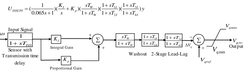
3.1 PI type SSSC controller structure
Fig. 2 shows the block diagra m o f PI type SSSC controlle r structure. Here Kp is the proportional ga in and KI is the integral ga in. The PI block is connected to a washout block(for high pass filter action) followed by a two stage Lead Lag
compensation block. The wash out block with time constant TW ma ke it sure that there is no steady state error of the voltage
reference due to the speed deviation ∆𝑤. Time constant TW is not critica l and may be in the range of 1 to 20 sec [12]. He re,
TW = 10s is taken into consideration. As the input signal (i.e. ∆𝑤) to the controller is remote signal, the sensor time with transmission time delay TTD = 65ms is provided at the input to the controller.
3 1 2 4 1 1 1 ( )( )( )( )( )
0.065 1 1 1 1
W I
I I
SSSCPI p
W I I
sT sT
K sT
U K y
s s sT sT sT
(4)
Fig. 2 Structure of PI type SSSC damping controller
3.2 PI type PSS controller structure
31 1 11 1 21 41 1 1 1 ( )( )( )( )( )
0.015 1 1 1 1
W I
I I
PSSPI p
W I I
sT sT
K sT
U K y
s s sT sT sT
(5)
Washout 2-Stage Lead-Lag W W sT sT 1 1 2 1 1 I I sT sT
11 34 I I sT sT q max V q min
V
Sensor with T ransmission timedelay Output I K p K qref V q V
Vqcnv
P roportional Gain 1
1sTTD
Fig. 3 Structure of PI type PSS damping controller
The controller gains and time constant parameters of PI type SSSC and PSS controlle r must be tuned for achieving
best performances. A first order sensor with sensor time de lay Ttd = 15ms is chosen by this controller for sensing the low frequency speed deviation ∆𝑤 during disturbances [8].
3.3. PI-PD type SSSC controller structure
Improved system performance is e xpected with the cascade control system. Fig. 4 shows a cascade PI-PD controller fo r
SSSC controller [7-10]. The performances are improved by putting a first order filter with tuning pole and filter constant N =
100 Similar PI-PD type PSS controller structure can be used for analysing the behaviour of PSS damping controller.
3
2 1
2 3 3
2 4
1 1
1
( )( )( )( )( )( )
0.065 1 1 1 1
W ID
I ID
SSSCPI PD p d p
W ID ID
sT sT
K sN sT
U K K K y
s s s N sT sT sT
(6)
Fig. 4 Structure of PI-PD type SSSC damping controller[19]
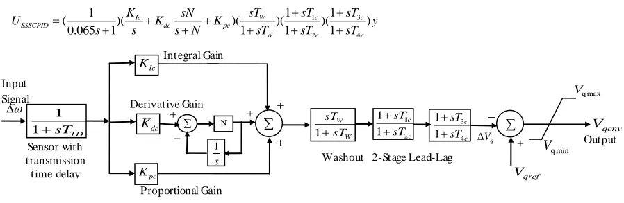
3.4 PID type SSSC controller structure
Conventional PID type SSSC controlle r structure is taken for co mparing the responses with the previous controller
structures. For the conventional PID type SSSC damping controller, the output is :
1 3
2 4
1 1
1
( )( )( )( )( )
0.065 1 1 1 1
Ic W c c
SSSCPID dc pc
W c c
K sN sT sT sT
U K K y
s s s N sT sT sT
(7)
Fig. 5 Structure of conventional PID type SSSC controller
Similar PID type PSS controller structure can be used for analysing the behavious of PSS damping controller s.
Here, Kpc, KIc Kdc, Kp1c, KI1c, Kd1c, T1c, T2c, T3c, T4c, T11c, T21c, T31c, T41c are gains and time constant parameters of PID
type SSSC and its PID type PSS controller that are to be tuned for achieving best performances [20].
Input Signal
Washout 2-Stage Lead-Lag
W W sT sT 1 1 2 1 1 c c sT sT 3 4 1 1 c c sT sT q max V q min V Sensor with transmission time delay Output Ic K pc K qref V q V
Vqcnv
dc K Derivative Gain Proportional Gain 1
1sTTD N
Integral Gain s 1 Input Signal
Washout 2-Stage Lead-Lag
W W sT sT 1 1 2 1 1 ID ID sT sT
34
1 1 ID ID sT sT q max V q min V Sensor with T ransmission time delay Output qref V q V qcnv V Proportional Gain 1 1sTTD
2
I
K 1
s 2 p K
Kd3
3 p K N 1 s Proportional Gain Derivative Gain Proportional Gain
Input Signal
Washout 2-Stage Lead-Lag 1 W W sT sT 11 21 1 1 I I sT sT 31 41 1 1 I I sT sT f max V f min
V
Sensortimedelay Output
1 I K 1 p K qref V q V
Vf
P roportional Gain 1
1sTtd
Integral Gain
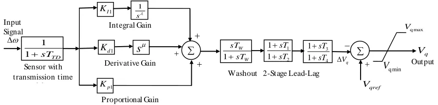
3.5 FOPID type SSSC controller structure
For fractional type SSSC controller, the output is:
3 1 2 4 1 1 1 ( )( )( )( )( )
0.065 1 1 1 1
W I
SSSCFPID d p
W
sT sT
K sT
U K s K y
s s sT sT sT
(8)
The proposed fractional PID type SSSC is a supplementary da mp ing controlle r whose structure is shown in Fig. 6, is to
modulate the SSSC injected voltageVq. Similar FOPID type PSS controlle r structure has been applied to analyse the damping behaviour. A first order sensor with sensor time de lay 𝑇𝑡𝑑=15ms is taken with this controller for sensing the low
frequency speed deviation w during disturbances. The controller gain 𝐾𝑝,𝐾𝐼𝐾𝑑,𝐾𝑝1,𝐾𝐼1, 𝐾𝑑1and the time constant values like𝑇1,𝑇2,𝑇3, 𝑇4,𝑇11,𝑇21,𝑇31,𝑇41,,
,
1 and 𝜇1are to be tuned optimally [21].Fig. 6 Structure of FOPID type SSSC damping controller
3.6. Control Objectives
Power system after passing through a large disturbance exhib it oscillation which can be minimized or quenched by
application of SSSC and this improves the stability. These oscillations are observed in terms of powe r angle, rotor speed
and line power. The objective is to reduce any one or all of these deviations. In the present study, an integral time absolute
error (ITA E) of the speed signals corresponding to the remote modes of oscillat ions is taken as the objective function. The
objective function is expressed as
dt t w J sim t t t . . 0
(9)where tsim is the simulat ion time period. The percentage overshoot and the settling time can be imp roved by minimizing this
objective function. The constraints here are the parameters of SSSC controlle r. The optimisation problem can be as the
following optimization problem: Minimizing J, and subject to
For PI type SSSC damping controller
min max
,
min maxp p p I I I
K
K
K
K
K
K
(10)min max min max min max min max
1I 1I 1I
,
2I 2I 2I,
3I 3I 3I,
4I 4I 4IT
T
T
T
T
T
T
T
T
T
T
T
(11)For PI type PSS controller
min max min max
1 1 1 , 1 1 1
p p p I I I
K K K K K K (12)
min max min max min max min max
11I 11I 11I
,
21I 21I 21I,
31I 31I 31I,
41I 41I 41IT
T
T
T
T
T
T
T
T
T
T
T
(13)For PI-PD type SSSC damping controller
1 s Input Signal
Washout 2-Stage Lead-Lag
W W sT sT 1 1 2 1 1 sT sT
34
1 1 sT sT q max V q min V Sensor with transmission time delay Output 1 p K qref V q V
Vq
1
d
K
s
Integral Gain
Derivative Gain
Proportional Gain 1
1sTTD
min max min max min max min max
2 2 2
,
2 2 2,
3 3 3,
3 3 3p p p I I I p p p d d d
K
K
K
K
K
K
K
K
K
K
K
K
(14)min max min max min max min max
1ID 1ID 1ID
,
2ID 2ID 2ID,
3ID 3ID 3ID,
4ID 4ID 4IDT
T
T
T
T
T
T
T
T
T
T
T
(15)For PI-PD type PSS controller
min max min max min max min max
12 12 12
,
12 12 12,
13 13 13,
13 13 13p p p I I I p p p d d d
K
K
K
K
K
K
K
K
K
K
K
K
(16)min max min max min max min max
11ID 11ID 11ID
,
21ID 21ID 21ID,
3ID 31ID 31ID,
41ID 41ID 41IDT
T
T
T
T
T
T
T
T
T
T
T
(17)For PID type SSSC damping controller
min max
,
min max,
min maxpc pc pc Ic Ic Ic dc dc dc
K
K
K
K
K
K
K
K
K
(18)min max min max min max min max
1c 1c 1c
,
2c 2c 2c,
3c 3c 3c,
4c 4c 4cT
T
T
T
T
T
T
T
T
T
T
T
(19)For PID type PSS controller
min max min max min max
1 1 1
,
1 1 1,
1 1 1p c p c p c I c I c I c d c d c d c
K
K
K
K
K
K
K
K
K
(20)min max min max min max min max
11c 11c 11c
,
21c 21c 21c,
31c 31c 31c,
41c 41c 41cT
T
T
T
T
T
T
T
T
T
T
T
(21)For FOPID type SSSC damping controller
min max min max min max
,
,
p p p I I I d d d
K
K
K
K
K
K
K
K
K
(22)max 4 4 min 4 max 3 3 min 3 max 2 2 min 2 max 1 1 min
1
T
T
,
T
T
T
,
T
T
T
,
T
T
T
T
(23)max
min
(24)For FOPID type PSS controller
min max min max min max
1 1 1
,
1 1 1,
1 1 1p p p I I I d d d
K
K
K
K
K
K
K
K
K
(25)min max min max min max min max
11 11 11
,
21 21 21,
31 31 31,
41 41 41T
T
T
T
T
T
T
T
T
T
T
T
(26)min max
1 1 1
(27)In this investigation DE and MFO techniques are applied to search for optima l set of SSSC-based damping controlle r
parameters. A brief introduction of Moth-Flame Optimization(MFO) technique is described in the next section.
4.
Overview of MFO
This has been wide ly used in many such important applications and giving very pro mising results. It is brie fly d iscussed
in this section to make the paper self-content. The behavior of the fly is mathe matica lly modeled by an algorithm ca lled
MFO algorith m, assuming the candidate solutions are moths and the problem’s variab les are the position of moths in the
space. This algorith m is a population-based algorithm, where the set of moths is represented in a matrixM consisting of the
array as their corresponding fitness values. The fla me matrix is represented by where the array of Falso stores the fitness
values.
The init ial point, final po int of the fla me and range of fluctuation of spira l in the search space are required for the spira l
movement of the moth which is expressed as
( , ) i i j
where Mi indicates the
i
-th moth position, Fi indicates thej
-th fla me position. Knowing the init ial point, final point of theflame and range of fluctuation of spiral in the search space, the spiral movement of the moth is expressed as
j bt
i j
i
F
D
e
Cos
t
F
M
S
(
,
)
.
.
(
2
)
(29)where t is a random number [-1, 1], and 𝐷𝑖 is the distance of the ith moth for the jth flame. And is calculated as:
i j
i F M
D (30)
where Mi indicates the ith moth, Fj indicates the jth fla me, and Di indicates the distance of the ith moth for the jth flame wh ich is to be minimized.
The next position of a moth is defined with respect to a fla me following Eq. (29). The t-para meter in the equation which
closeness to flame equals to -1 and 1 imp lies farther to the fla me. Due to change of order of fla mes and revision of moth’s
position at each iteration, the e xp loitation of the pro misingly best solutions is obtained through an adaptive mechanism
proposed by using the number of flames.
) 1 * ( _
T N l N round no
flame (31)
where N and T represents ma ximu m no. of fla mes, and iterat ions respectively, l is the current nu mber of iteration. The algorithm flow chart is shown in Fig. 7.
5.
Simulation Results And Analysis
The system described in Fig. 1 is simulated in MATLA B under three phase disturbance at different locations. The
objective function is min imised by tuning the fractional PID type SSSC and PSS controller para meters with M FO and
compared with DE algorith m as shown in Tab le 4. The result is compared with PI type SSSC and PSS (Table 1), PI-PD type
SSSC and PSS (Table 2), PID type SSSC and PSS da mp ing controllers (Tab le 3). The robustness and effectiveness of the
proposed FPID type SSSC and PSS is verified at va rious generator loadings. After hundred iterations, the optimized
parameters a long with the performance indices of ITAE are noted down fro m both DE and MFO a lgorithms. The simu lation
results for all controllers are shown in Figs. 8-11.
5.1. Case-1: PI type SSSC-PSS Controller
The nomina l loading 0
0
(0.8 . ,p u 48.48 ), is the Self-clea red between Bus-2 and Bus-3. A three phase line fault is
created at one of the double section line between Bus -2 and Bus-3 at t = 1s in SMIB power system for nominal loading and
self-clea red for5 cycles. The post fault oscillat ion are da mped out through MFO and DE optimised PI type SSSC and PSS
controller and the effective results are found through MFO optimized para meters. The para meters comparison is shown in
table-1 and the simulat ion responses are shown in Figs. 8-11with the legend “PI type SSSC (MFO)” with a solid green line
and “PI type SSSC (DE)” with dotted pink line.
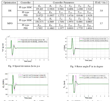
Table 1 DE and MFO tuned optimal parameter of PI type SSSC and PSS controller at nominal loading(0.8 . ,p u
0 48.48 )0Optimisation Controller Controller Parameters ITAE *10e-3
DE
PI type SSSC Kp KI T1I T2I T3I T4I
3.8 195.403 12.9818 0.5881 0.6896 1.4308 1.9145
PI type PSS
Kp1 KI1 T11I T21I T31I T41I 21.0723 11.0937 1.2773 1.6716 0.0146 1.9139
MFO
PI type SSSC Kp KI T1I T2I T3I T4I
3.7 158.3171 6.3069 1.7456 1.9974 0.4081 0.8803
PI type PSS
Kp1 KI1 T11I T21I T31I T41I 1.7652 11.4863 1.1977 0.0010 1.7735 1.6014
Fig. 8 Speed deviation
w
in p.u Fig. 9 Rotor angle
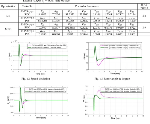
in in degree5.2. Case-2:PI-PD type SSSC and PSS controller
The nominal loading(0.8 . ,p u
048.48 )0 , is the self-clea red at between Bus-2 and Bus-3. Table 2 shows the optimisedparameters with both DE and MFO for PI-PD type SSSC and PSS controller during three phase Bus-2 and Bus-3 and
self-cleared condition fo r 5 cyc les . The effective responses are analysed in Fig.9. It is observed in Fig. 12-15 for speed deviation,
tie line power and termina l voltage. The improve ment of settling time and decrement of overshot of transient responses are
observed in this MFO optimised PI-PD type SSSC and PSS controller more effectively than controller.
Table 2 DE and MFO tuned optimal parameter of PI-PD type SSSC and PSS controller with nominal
loading 0
0
(0.8 . ,p u 48.48 )line outage
Optimisation Controller Controller Parameters ITAE
*10e-3
DE
PI-PD type SSSC
Kp2 KI2 Kp3 Kd3 T1ID T2ID T3ID T4ID
4.2 8.9062 7.7024 91.2532 32.1083 0.9168 1.7648 0.2907 0.7114
PI-PD type PSS
Kp12 KI12 Kp13 Kd13 T11ID T21ID T31ID T41ID
55.8208 17.3684 15.7298 12.5812 0.8535 1.4744 0.2200 1.4390
M FO
PI-PD type SSSC
Kp2 KI2 Kp3 Kd3 T1ID T2ID T3ID T4ID
2.9 0.9990 8.2677 102.8586 92.6227 1.0339 0.6070 0.9069 1.6722
PI-PD type PSS
Kp12 KI12 Kp13 Kd13 T11ID T21ID T31ID T41ID
0.9990 0.0000 99.87 9.3844 0.0001 1.9974 0.0001 1.8503
Fig. 12 Speed deviation Fig. 13 Rotor angle in degree
Fig. 14 Tie line active power Fig. 15 Terminal voltage
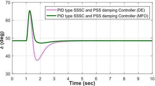
5.3. Case-3: PID type SSSC and PSS controller
The nominal loading at ( 0
0
0.8, 48.4
e
P ), is the line outage Bus -2 and Bus-3. PID type SSSC and PSS controlle r
has also been tested with this SMIB system at line outage disturbance condition at same fault location between Bus -2 and
Bus-3.The three phase line outage disturbance is done at t = 1s for 5 cycles and the e ffective responses are analysed in Figs.
16-18 following optimized controlle r para meters in table -3. It is found that, the responses for PID type SSSC and PSS
controller are better as co mpared to PI and PI-PD type SSSC and PSS controlle r. The M FO optimized controller para meters
of PID type SSSC and PSS g ives better responses than the DE tuned PID type SSSC and PSS controlle r. The settling time in
Fig. 16 Speed deviation
Fig. 17 The line active power Fig. 18 SSSC-injected voltage
Table 3 DE and MFO tuned optimal parameter of PID type SSSC and PSS controller with nominal loading (0.8p
0 0
(0.8 . ,p u 48.48 ), line outage
Optimisation Controller Controller Parameters ITAE *10e-3
DE
PID type SSSC
Kpc KIc Kdc T1c T2c T3c T4c
3.7 134.1158 13.9487 12.3751 1.7451 1.5531 0.2802 0.5056
PID type PSS
Kp1c KI1c Kd1c T11c T21c T31c T41c 111.8589 10.1969 48.8007 1.559 0.4859 0.1774 1.6069
MFO
PID type SSSC
Kpc KIc Kdc T1c T2c T3c T4c
3.2 469.7830 3.2563 18.4041 1.4773 1.6225 1.1597 1.7668
PID type PSS
Kp1c KI1c Kd1c T11c T21c T31c T41c 0.9990 40.4269 2.4261 0.7406 1.8584 1.8608 1.8763
5.4. Case-4: Fractional PID type SSSC and PSS controller
The nominal loading at (
P
e
0.8,
0
48.4
0) line outage disturbance is at Bus-1. The proposed fractional PID type SSSC and PSS controllers have been imple mented in this work to show their better quality over all the controllers. Thetransient analysis is done for the line outage disturbances of SMIB test system at no minal loading. The d isturbance is create d
at 1 sec at one of the double circuit transmission line for 5 cycles and simulat ion results are studied from the Fig. 19-22 for
speed deviation, tie line active power, terminal voltage and SSSC injected voltage , respectively. The settling time, overshoot
and undershoot of the transient responses are improved effect ively with this proposed controller as shown in Table 4. The
time de lay of 50 m sec is introduced between the FOPID type SSSC and PSS. Optimized with M FO algorith m, the proposed
controller significantly improves the transient response as compared to DE optimized FOPID type SSSC and PSS controller
and all other controllers.
Table 4 Case-4: DE and MFO tuned optimal parameter of FOPID type SSSC and PSS controller with nominal
Fig. 19 Speed deviation Fig. 20 Terminal voltage
Fig. 21 Tie line active power Fig. 22 SSSC-injected voltage controller
5.5 Case-5: Fractional PID type SSSC and PSS controller
The nomina l loading at
(0.8 . ,
p u
0
48.48 )
0 line outage disturbance is between Bus-2 and Bus-3. The MFOoptimized speed responses of all the controllers are taken together in Fig. 23 and revealed that, the fractional PID with
fractional number of integral ga in and derivative gain e ffective ly improves the dynamic responses as compared to rest of the
controllers. The zoo m portion of speed deviation shown in Fig. 24 c learly shows the speed response has no second overshoot,
undershoot is less and it takes 2 sec to settle for damping out the complete oscillation s.
Optimisation Controller Controller Parameters ITAE
*10e-3
DE
FPID type SSSC kp kI kd T1 T2 T3 T4 μ
3.4 294.7739 54.5911 16.8004 0.5892 1.1404 1.6048 0.7965 0.6887 0.9087
FPID type PSS kp1 KI1 kd1 T11 T21 T31 T41 1 μ1
57.7629 11.4368 31.4137 0.2451 1.3925 0.2039 0.9830 0.4103 0.9008
M FO
FPID type SSSC KP KI Kd T1 T2 T3 T4 μ
2.9 100.2096 37.6333 8.6803 1.8305 1.9974 1.5018 1.7566 1.0185 0.9987
FPID type PSS KP1 KI1 Kd1 T11 T21 T31 T41 1 μ1
161.2293 94.0954 27.9560 0.0920 0.0001 0.5633 1.4125 1.1644 1.1644
Fig. 23 Speed deviation for different controllers compared with proposed FOPID type SSSC and PSS controller
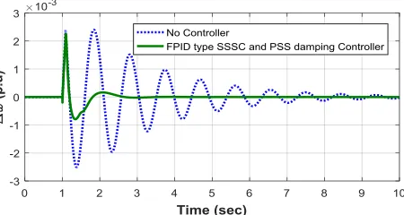
5.6. Case-6: FOPID type SSSC and PSS controllernominal loading, permanent line tripping
Under severe disturbance condition, the proposed controller is verified at nominal loading. A three phase fault for 5
cycles is created at the mid-point of the overhead line of Bus -2 and Bus-3 and the fault is clea red by indefin ite tripping of the
faulted section. The responses of the system are shown in the Figs. 25-27. The speed deviation is shown in Fig. 25 in p.u, the
rotor angle in deg in Fig. 26, and the healthy line power PL2 in MW in Fig. 27, respectively. The system responses are
unstable without the controller and becomes stable by FOPID type SSSC type PSS da mping controller. This controlle r brings
the initia l operating point of the speed deviation at 3 sec and the rotor angle in Fig. 26 is shifted to another operating point at
60°from its initial angle of 48.48°after 2.6 sec.
Fig. 25 Speed deviation in p.u.
Fig. 26 Rotor angle in degree Fig. 27 Power at healthy line
5.7. Case-7: FPID type SSSC and PSS controller With light loading 0
(0.4 . , 22.85 )p u and self-clearing, light load perfo rmances are a lso performed by changing the
generator loading and the stability of the SMIB system is checked with the proposed FPID type SSSC and PSS da mping
controller. The responses are shown in the Fig. 28-30 with three phase fault for 5 cyc les at middle of the double transmission
line. The rotor angle in Fig. 29 reduces 0
22.85 (without controller) to 0
22.5 (with controller) and settling time is achieved at 3 sec. The e ffect iveness of this proposed controller is also verified in Fig s. 28, 30 and 31 by showing the da mping of the
oscillations and reduced overshoot and undershoot after the first swing.
Fig. 29 Rotor angle Fig. 30 Tie line Powerin MW
6.
Conclusions
The main purpose here is to damp the powe r system oscillat ions and to enhance the system performance under
disturbances. The coordinated PI, PI-PD, PID and FPID type SSSC and PSS da mping controllers are designed and
imple mented in SMIB power system. The perfo rmance of Fractional PID type SSSC and PSS has been compared with other
controllers by its ITAE based on speed deviation of the test system and found minimu m ITA E as objective function . With
optimizing the controller para meters by MFO, the robustness and effectiveness are verified under various contingencies. The
system damping has also been compared by using proposed controller with DE, and has concluded that the MFO technique
yields better ITA E value and better dynamic response. The simu lation work has been done in MATLA B environ ment by
running several times with adjusting controlling variables F= 0.5-0.8, CR= 0.5-0.8, strategy=1-3, iteration, populations and
the range of other controller para meters within its limit in DE technique. Results obtained are good. However, in the
proposed controller, 50 iterations, 10 population, F=0.8, CR=0.8, strategy=3 are co nsidered and much better result are
obtained. Similarly, 5 agents and 50 iterat ions are taken for MFO technique for still better results as co mpared to DE in this
proposed test systems.
The results indicate the e ffectiveness of the proposed designs in prov iding good damp ing characterist ics to power
system oscillat ions. This also helps in enhancement of dynamic performance. This approach can be imp le mented with mult
i-machine grid connected power systems.
References
[1] S. Mirjalili, “Moth-flame optimization algorithm: A novel nature-inspired heuristic paradigm,” Knowledge-Based System, vol. 89, pp. 228-249, November 2015.
[2] S. M. H. Hosseini, H. samad zadeh, J. Olamaei, and M. Farsadi, “SSR mitigation with SSSC thanks to fuzzy control,” Turkish Journal of Electrical Engineering & Computer Sciences, vol. 21, pp. 2294-2306, January 2013.
[3] M. Klein, G. J. Rogers, and P. Kundur, “A fundamental study of inter-area oscillation in power systems,” IEEE Press, August 1991, pp. 914-921.
[4] C. Liu, G. Ca i, and D. Yang, “Design nonlinear robust damping controlle r for static synchronous series compensator based on objective holographic feedback-H,” Journal of advances in Mechanical Engineering (Sage Journal), vol. 8, no. 6, pp. 1-11, June 2016.
[5] M. Bongiorno, J. Svensson, and L. Angquist, “On control of static synchronous series compensator for SSR mitigation,” IEEE Transactions on Power Electronics, IEEE Press, June 2007, pp. 735-743.
[6] L. Bangjun and F. Shu min, “A brand new nonlinear robust control design of SSSC for transient stability and damp ing improve ment of mu lti-machine power systems via pseudo-generalized Ha miltonian theory,” Control Engineering Practice, vol. 29, pp. 147-157, August 2014.
[8] M. S. Castro, H. M. Ayres, V. F. da Costa, and L. C. P. da Silva, “Impacts of the SSSC control modes on small-signal and transient stability of a power system,” Electrical Power System Research, vol. 77, no. 1, pp. 1-9, January 2007. [9] M. A. Abido, “Pole p lacement technique for PSS and TCSC based stabilizer design using simulated annealing,”
International Journal of Electrical Power Systems Research, vol. 22, no. 8, pp. 543-554, November 2000.
[10] M. E. About-Ela, A. A. Sa lla m, J. D. Mc Ca lley, and A. A. Fouad, “Damp ing controller design for power system oscillations using global signals,” IEEE Transactions on Power Systems, IEEE Press, May 1996, pp. 767-773.
[11] M. A. Abido, “Optimal design of power system stabilizers using particle swarm optimization,” IEEE Trans Energy Convers, IEEE Press, November 2002, pp. 406-413.
[12] Z. L. Gaing, “A particle swarm optimization approach for optimu m design of PID controller in A VR system,” IEEE Trans Energy Convers 19, IEEE Press, May 2004, pp. 384-391.
[13] S. Panda, “Robust coordinated design of multiple and mu lti-type damping controller using differential evolution algorithm,” International Journal of Electrical Power & Energy Systems, vol. 33, no. 4, pp. 1018-1030, May 2011. [14] H. E. Mostafa, M. A. El-Sharkawy, A. A. Emary, and K. Yassin, “Design and a llocation of powe r system stabilize rs
using the particle swarm optimization technique for an interconnected power system,” Int ernational Journal Electrical Power Energy Systems., vol. 34, no. 1, pp. 57-65, January 2012.
[15] T. T. Nguyen and R. Gianto, “Application of optimization method for control co-ordination of PSSs and facts devices to enhance small-disturbance stability,” Proc. IEEE PES Transmission & Distribution Conf. May Da llas, IEEE Press, May 2006, pp. 21-24.
[16] Y. Li and K. H. Ang, “PID control system analysis and design,” IEEE Control Systems. Magazines, IEEE Press, June 2005, pp. 559-576.
[17] C. H. Lee and F. K. Chang, “Fractional-order PID controller optimization v ia improved electro magnetis m-like algorithm,” Expert Systems With Application, vol. 37, no. 12, pp. 8871-8878, December 2010.
[18] F. Padula and A. Visioli, “Tuning rules for optimal PID and fractional-order PID controllers,” Journal of Process Control, vol. 21, no. 1, pp. 69-81, January 2011.
[19] R. K. Khadanga and J. K. Satapathy, “Time delay approach for PSS and SSSC based coordinated controller design using hybrid PSO-GSA algorith m,” International Journal of Electrica l Powe r and Energy Systems, vol. 71, pp. 262 -273, October 2015.
[20] S. S. Mohamed, A. E. Mansour, and M. A. Abdel Ghany, “Design of fractional order PID controller for SMIB power system with UPFC tuned by mu lti-object ives genetic algorith m,” Proc. 16th Int. Conf. On Aerospace sciences & Aviation technology, pp. 26-28, May 2015.
![Fig. 1 The Single Machine Infinite Bus (SMIB) Power System with a SSSC[2-3]](https://thumb-us.123doks.com/thumbv2/123dok_us/9833080.1969485/2.596.158.398.414.523/fig-single-machine-infinite-bus-smib-power-sssc.webp)
![Fig. 7 Flow chart of the proposed MFO algorithm[1]](https://thumb-us.123doks.com/thumbv2/123dok_us/9833080.1969485/7.596.158.427.357.764/fig-flow-chart-proposed-mfo-algorithm.webp)