Envelopes of optical interference spectra for duplex
and triplex layered structures
Kosobutskyy P.S.1 and Kushnir O.P.2
1National University “Lviv Polytechnics”, P. O. Box 4544, 79053 Lviv-53, Ukraine, E-mail: [email protected]
2Lviv State Agrarian University, 1 V. Velykyi St., Dublyany, 80381 Lviv Region, Ukraine, E-mail: [email protected]
Received: 10.01.2008 Abstract
We have found analytical expressions for the envelopes of maxima and minima of interference reflection and transmission spectra for both transparent and absorbing two- and three-layer structures under the conditions of arbitrary light incidence and polarization state. General regularities for the shape of those spectral envelopes are established, depending on the optical thicknesses of constituent layers.
Keywords: reflection spectra envelopes, thin film, two- and three-layer structures.
PACS: 63.22.+m; 78.30-j; 78.30.Fs; 78.66.Hf
UDC: 535.391.4
1. Introduction
General relations determining envelopes of Fabri-Perot interference spectra for arbitrary experimental geometries and light polarizations have been derived only recently for the simplest case of single-layer structures [1]. For the structures involving larger quantities of layers, it has been suggested [2] that analytical relations for those spectral envelopes can be hardly obtained even for the case of two optically transparent films, despite the Fabri-Perot interference has been extensively studied for a long time∗. In order to solve the corresponding problems and determine optical constants and thickness of a film under study, a method of additional spectral modulation has been proposed. It can be implemented by means of light interference in an intermediate layer, which is chosen to be thicker than the film under test [2]. Reasoning from obvious practical importance of two- and three-layer structures for constructing devices of optical signal processing [5,6], in this work we reveal for the first time general analytical expressions for the envelopes
of Fabri-Perot interference spectra characteristic of two- and three-layer structures, together with general features of the shape of those envelopes.
2. Basic relations and the main conclusions
Let a plane wave of d1 or p−polarization propagates through a uniform semi-infinite medium with the refractive index n0 and then falls upon a surface of k isotropic layers at an arbitrary incidence angle
α
. Each of the layers is characterized with complex refractive index nj=nj−iχj and a thickness dj, where j=1,2,...k and k=2 or 3 . Under the conditions of oblique light incidence upon the structure surface, each layer hasthe phase thickness 4 j cos
j j j
d n π δ β λ =
, where βj is the refraction angle for the
interface of film under the number j. The layered system is fixed at a uniform semi-infinite substrate characterized by a complex refractive index nk+1.
The complex amplitude reflectances ( ,
, , l m i l m l m
r σ e−φ
=
) and transmittances
( ,
, , l m i l m l m
t =τ e−ϕ ) for single surfaces or the structures formed by layers with the numbers
l, l+1, …, m–1, m (with l=0,1,...,k, m l= +1,l+2,...,k+1 and the layers l and m
representing semi-infinite media) can be found according to the known Fresnel formulae [7] for the both light polarizations, if only m l= +1. If m l> +1, those coefficients could be found while multiplying the matrices
(
)
(
)
(
)
(
)
(
)
(
)
1, 2 , 1
, ,11 , ,12
, 1 1, 2 1 1
, ,21 , ,22
2, 3 1,
2, 3 2 2 1, 1 1
1 1
1 exp exp
1 1
exp exp exp exp
l l l l
l m l m
l l l l l l
l m l m
l l m m
l l l l m m m m
r r
M M
r r i i
M M
r r
r i i r i i
δ δ
δ δ δ δ
+ + + + + + + + + + − + + + + − − − = × − − × ×⋅⋅⋅× − − − − , (1) namely , ,21 , , ,11 l m l m l m M r M =
, (2)
and
1
2 , 1 , 1
1 ,
, ,11
j
m i
l l j j j
j l l m
l m
t t e
t M δ − − + + = +
⋅ Ω ⋅
=
∏
, (3)
where Ω =j exp Im
(
δj)
and δj=Reδj.It is worth noticing that a number of misprints are available in the Russian translation of monograph by Azzam and Bashara [8]. So, the amplitude transmittance
coefficient 21 1 t S =
(see [8]) should be defined as 11 1 t S =
, where the quantities S11,21 are given respectively
by formulae (4.184a) and (4.184b) from [8]. Besides, formula (4.186) of [8] is also in error. Using the notation adopted in the monograph mentioned above, we have in fact
1 2
1 1 2
( ) 01 12 23
2 2 2
01 12 12 01 23
(1 ) ( )
i
i i i
t t t e t
r r e r r e r e
β β
β β β
− + − − − = + + +
. Note that the latter relation agrees with
Eq. (3). Finally, quite analogous correction should be made for the single-film
transmittance coefficient, i.e. 1 1
1 1
01 12 01 12
2 2
01 12 1 01 12
i i
i i
t t e t t e
r r e r r e
β β β β − − − → − + + .
Let us consider, for instance, a single film formed by the surfaces 01 and 12 . The essence of the envelope technique consists in representing the energy reflectance (R) and transmittance (T ) coefficients for that film in the following form:
2 2 2 2
2 2 2 2
cos sin
2 2
1 cos 1 sin
2 2
m M
F F
R b R a
R F F b a + + − − + − = =
+ − , 1 2sin2 1 2cos2
2 2
m M
T T
T
F F
a − b −
= =
− + , (4)
where
(
)
2 01 12 1 2 01 12 1 4
1
a σ σ
σ σ
Ω =
+ Ω ,
(
)
2 01 12 1 2 01 12 1 4
1
b σ σ
σ σ
Ω =
− Ω and
1 01 12 2
F± =δ φ± −φ . The functions
2 01 12 1 ,
01 12 1 1
M m
R σ σ
σ σ
± Ω
=
± Ω
,
(
)
2 2 01 12 1
2 2
, 2
0 01 12 1
cos cos 1 M m n T n τ τ β
α σ σ
Ω =
Ω
∓ (5)
are analytical expressions of the spectral envelopes. In frame of our approach, the adherent points of the reflectivity maxima envelopes are determined by the conditions
2sin2 0 2
F
a ± = , while the same points for the minima are given by 2cos2 0 2
F
b ± = . They
do not always coincide with the peak extrema. The differences RM −Rm and TM −Tm
determine the ranges of the energy coefficients that correspond to changes in geometrical layer thickness, under condition of invariable optical parameters of the media. This is why the maxima and minima envelopes are kept parallel and retain their slopes for the case of transparent single-layer structure in any dispersion-free spectral region.
3. Two-layer structures
Using standard computer modelling techniques, we have revealed that the envelopes of the multiple interference spectra for the case of two films acquire the following form:
2 02 23 1 2 ,
02 23 1 2 1
M m
R σ σ
σ σ
± Ω Ω
=
± Ω Ω
,
(
)
2 2 3 3 02 23 2
, 2
0 02 23 2
cos cos 1 M m n T n
β τ τ
α σ σ
Ω =
Ω
∓ , (6)
2 01 13 1 ,
01 13 1 1
M m
R σ σ
σ σ ± Ω
=
± Ω
,
(
)
2 2 3 3 01 13 1
, 2
0 01 13 1
cos
cos 1
M m
n T
n
β τ τ
α σ σ
Ω =
Ω
∓ (7)
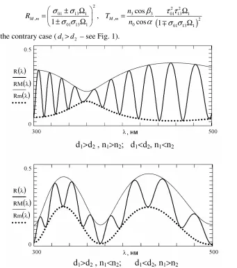
in the contrary case (d1>d2 – see Fig. 1).
Fig. 1. R( )λ spectra and their envelopes Rm M, ( )λ for the case of two-layer
structure.
Eqs. (6) and (7) have a general character and remain valid for optically transparent and absorbing structures, for normal and oblique incidence, as well as for both the
s
−
and p−polarizations. Their analysis draws a conclusion that it is the light interference in the thinnest film that plays a key role in shaping the envelope contours of Fabri-Perot spectra typical for the two-film structures.Furthermore, the analytical relations given by Eqs. (6) and (7) allow formulating a general antireflecting condition for the optical system consisting of two films:
02 23 1 2
Fig. 2), which represents an analogue of ordinary Brewster angle [9]. Let us stress that the general antireflecting condition is not forbidden for either normal or oblique light incidence and for the both s− and p−polarizations.
Fig. 2. Illustration of ' antireflecting' angle αps and the Brewster angle αB01.
Let us consider single interfaces appearing between the medium deposited above the structure and the upper film (the corresponding interface index 01), between the two films (the index 12) and between the lower film and the substrate (the index 23). It is known
[10] that the Brewster angles 1
01 2 2
0 1 arcsin
B
n
n n
α =
+ ,
1 2
12 2 2
0 1 2
1 arcsin
B
n n
n n n
α =
+ and
2 3
23 2 2
0 2 3
1 arcsin
B
n n
n n n
α =
+ exist for those single interfaces in case of the oblique
incidence and the p−polarization. In what the interference properties of this two-layer system are concerned, it becomes similar to its single-layer analogue whenever the incident light falls at those Brewster angles.
the interference technique. When the incident angle equals to αB12, the envelopes also do not oscillate, however the oscillation period for the reflectance contour is determined by the total phase thickness of the both films.
On the other hand, the envelopes coincide at the corresponding Brewster angles for the single interfaces, i.e.
M m
R =R . (9)
If we have had experimental contours of the dependences of energy reflection coefficient on the incidence angle, the fact summarized by Eq. (9) enables us to find the values of the angles αB01 (d1>d2) or αB23 (d1<d2) as a corresponding intercept.
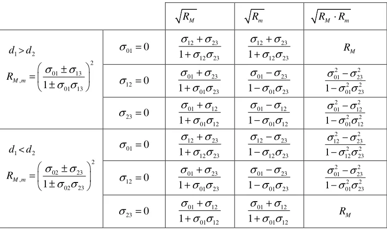
Table 1. Envelope functions Rm M, for the incident angles αB01, αB12 and αB23 and different relationships between the layer thicknesses d1 and d2.
M
R Rm RM⋅Rm
01 0
σ = 12 23
12 23 1 σ σ σ σ + + 12 23 12 23 1 σ σ σ σ +
+ RM
12 0
σ = 01 23
01 23 1
σ σ
σ σ
+
+ 1 01 01 2323
σ σ σ σ − − 2 2 01 23 2 2 01 23 1 σ σ σ σ − − 1
d >d2
2 01 13 , 01 13 1 M m
R σ σ
σ σ ± = ± 23 0
σ = 01 12
01 12 1 σ σ σ σ + + 01 12 01 12 1 σ σ σ σ − − 2 2 01 12 2 2 01 12 1 σ σ σ σ − − 01 0
σ = 12 23
12 23 1
σ σ
σ σ
+
+ 1 12 12 2323
σ σ σ σ − − 2 2 12 23 2 2 12 23 1 σ σ σ σ − − 12 0
σ = 01 23
01 23 1 σ σ σ σ + + 01 23 01 23 1 σ σ σ σ − − 2 2 01 23 2 2 01 23 1 σ σ σ σ − − 1
d <d2
2 02 23 , 02 23 1 M m
R σ σ
σ σ ± = ± 23 0
σ = 01 12
01 12 1
σ σ
σ σ
+
+ 1 01 01 1212
σ σ
σ σ
+
+ RM
Another important conclusion may be inferred from Eq. (9). Namely, the single- and two-layer structures manifest quite different phenomena of multiple-beam interference at the Brewster angles. So, the multiple-beam interference in the two-layer system remains actual under the condition specified by Eq. (9). On the contrary, the main features of light reflection and transmission in the single-layer system under the above condition prove to be the same as those peculiar for a single interface. If we deal with absorbing media, the physical meaning of our conclusions does not change. Then the Brewster angle becomes a so-called 'pseudo-angle' and is determined from the solution of equations Re rp=0 or
0 p
dR
4. Three-layer structures
Using the computer analysis of three-layer systems, we have ascertained that the analytical expressions for the envelope spectra of multi-beam interference may be generalized to the following form:
2 03 34 1 2 3 ,
03 34 1 2 3 1
M m
R σ σ
σ σ
± Ω Ω Ω
=
± Ω Ω Ω
,
(
)
2 2 03 34 3
4 4
, 2
0 03 34 3
cos
cos 1
M m
n T
n
τ τ β
α σ σ
Ω =
Ω
∓ , (10)
if the geometric thicknesses of the layers obey the inequality d1<d3, while for the case of d1>d3 we have
2 01 14 1 ,
01 14 1 1
M m
R σ σ
σ σ
± Ω
=
± Ω
,
(
)
2 2 01 14 1
4 4
, 2
0 01 14 1
cos
cos 1
M m
n T
n
τ τ β
α σ σ
Ω =
Ω
∓ . (11)
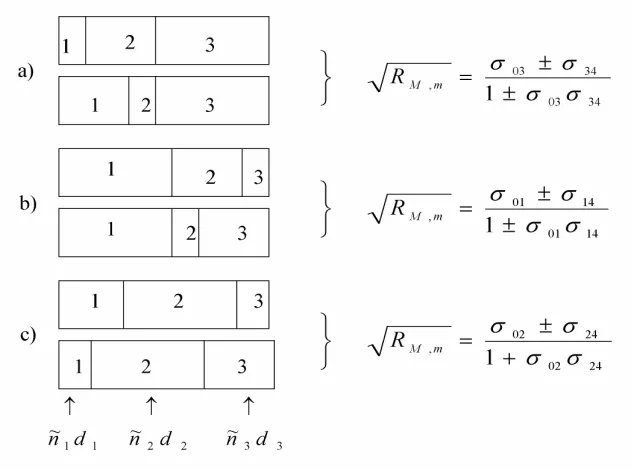
Eqs. (10) and (11) have a general character, too. As follows from Fig. 3, the conclusion concerning the interference in the thinner film as a major factor of shaping the corresponding spectral envelope, which has been drawn earlier, remains also valid for the three-layer system.
Fig. 3. Illustration of modulation of the envelope with the light interference in layered system. The oscillation period of the envelope contour Rm M, is the same as that for the contour σ03 (a), σ14 (b), σ02 or σ24 (c).
The antireflecting condition for the three-layer system appears to be analogous to Eq. (8):
03 34 1 2 3
It expresses pseudo-Brewster 'optical blooming' occurred at the αps angle. Depending upon the relations among the refractive indices, in case of four interfaces we have the following allowed Brewster angles for the
p
−
polarization:1
01 2 2
0 1 arcsin
B
n
n n
α =
+ ,
1 2
12 2 2
0 1 2
1 arcsin
B
n n
n n n
α =
+ ,
2 3
23 2 2
0 2 3
1 arcsin
B
n n
n n n
α =
+ and
3 4
34 2 2
0 3 4
1 arcsin
B
n n
n n n
α =
+ . As for the multi-beam interference, the three-layer system at
these angles behaves like the two-layer one.
5. Conclusions
1. We have derived general analytical expressions for the envelope Fabri-Perot interferograms for the duplex and triplex thin-film structures.
2. Interference of light in the thinnest layer has been shown to be deciding while shaping their envelope contours.
3. Basing on the analytical expressions for the envelopes, we have generalized antireflecting optical conditions and manifestation of the Brewster angles in the Fabri-Perot spectra.
Besides, we should emphasize the following point. Unfortunately, the algorithm for searching for explicit mathematical expressions that define the envelopes for the two- and three-layer structures still remains unclear. Nonetheless, we have proved that the conclusion [2] on principled impossibility to find these expressions, even for the simplest case of two-film system, should be incorrect. This is another important result of our work.
References
1. Kosobutskyy P S and Morgulis A, 2004. Modelling of reflection and transmission spectroscopies of single-layer Fabri-Perot interferometers using the envelope method. Opt. Zhurn. 71: 63–68.
2. Filippov V V, 2006. Envelope technique for the studies of two-film system lying on reflecting substrate. Opt. Spektrosk. 101: 485–489.
3. Arndt D P, Azzam R M A, Bennett J M , Borgogno JP, Carniglia C K, Case W E, Dobrowolski J A, Gibson U J, Tuttle Hart T, Ho F C, Hodgkin V A, Klapp W P, Macleod H A, Pelletier E, Purvis M K, Quinn D M, Strome D H, Swenson R, Temple P A, Thonn T F, 1984. Multiple determination of the optical constants of thin-film coating materials. Appl. Opt. 23: 3571–3596.
4. Kutavichus V, Filippov V and Huzouski V, 2006. Determination of optical parameters and thickness of weakly absorbing thin films from reflectance and transmittance spectra. Appl. Opt. 45: 4547–4553.
5. Macleod H A Thin-Film Optical Filters. Bristol: Adam Hilger Ltd (1986).
monocrystalline silicon substrate. Opt. Mater. 29: 1768–1773.
7. Born M. and Volf E. Fundamentals of Optics. Moscow: Nauka (1970).
8. Azzam R. M. A. and Bashara N. M. Ellipsometry and Polarized Light. Moscow: Mir (1981).
9. Kosobutskyy P S and Kushnir O P, 2007. Regularities of manifestation of the Brewster and pseudo-Brewster angular conditions in spectra of light reflection from a thin transparent layer. Ukr. J. Phys. 52: 225–228.
10. Surdutivich G I, Vitlina R Z and Baranauskas V, 1999. Simple reflectometric method for measurement of weakly absorbing films. Thin Solid Films. 355–356: 446–450. 11. Shigeki Takeuchi, Shoji Nitta, Yukihiro Yamada and Shuichi Nonomura, 1996.
![Fig. 2), which represents an analogue of ordinary Brewster angle [general antireflecting condition is not forbidden for either normal or oblique light incidence and for the both 9]](https://thumb-us.123doks.com/thumbv2/123dok_us/9755235.1960202/5.595.135.465.150.369/represents-analogue-ordinary-brewster-antireflecting-condition-forbidden-incidence.webp)