Vol.6 (2016) No. 6
ISSN: 2088-5334
The Algorithm of Image Edge Detection on Panoramic Dental X-Ray
Using Multiple Morphological Gradient (mMG) Method
Jufriadif Na`am
#, Johan Harlan
*1, Sarifuddin Madenda
*2, Eri Prasetio Wibowo
*3 #Computer Science Faculty, Universitas Putra Indonesia YPTK Padang, 25221, Indonesia E-mail: [email protected]
*Computer Science Faculty, Gunadarma University, Jakarta, 16424, Indonesia
E-mail: [email protected]; [email protected]; [email protected]
Abstract— Dental caries is tooth decay caused by bacterial infections. It is commonly known as cavities. This infection causes
demineralization and hence destruction of the teeth. Diagnosis of dental caries is conventionally facilitated with radiographical films. This research aims to develop some algorithm of the mMG method in identifying dental caries based using digital panoramic dental x-ray images. This paper presents an algorithm of using digital panoramic dental x-ray images to detect dental caries. Type of algorithm used in this study is normal mMG, Enhancement mMG, and Smooth mMG. This study makes use of MATLAB and it performs dental caries detection in three algorithms. A dataset of 225 digital panoramic dental x-ray images in .png format is used to edge detection of the object in dental. The results are helpful to identify such caries from the tooth.
Keywords— panoramic dental x-ray; dental caries; multiple morphological gradient (mMG); algorithm; smooth; enhancement
I. INTRODUCTION
Dental caries is tooth decay which commonly known as cavities. It is one of the most prevalent chronic diseases worldwide [1]. Dental caries is a microbiologic disease which causes the dissolution of the mineral structure of teeth [2].
The location of dental caries can be grouped into two. Group 1 is the gap or fissures of teeth. This place is highly favored to be the location of dental caries. Gap and fissure caries are difficult to detect. The continued development of perforation process results in a deeper hole. When caries has reached a dentin or intersection of email and dentin, the hole will be widened. This perforation process in dentin will follow a triangular pattern toward the dental pulp.
Group 2 is smooth surface. Smooth surface caries consists of three, namely: (a) proximal caries (interproximal). This is caries on smooth surfaces formed between adjacent teeth or between the teeth; (b) Root caries. This caries is formed on the surface of the tooth root, and (c) other smooth surface caries.
Classification of caries is based on location, etiology, rate of progression and affected hard tissues. This classification is useful in characterizing a particular case of tooth decay. Classes based on above criteria are useful for representing the condition of a tooth more accurately. Caries classification on the basis of location is shown in Fig. 1 [3].
(a) (b)
(b) (d)
Fig. 1 Types of caries: (a) occlusal caries, (b) interproximal caries, (c) enamel caries, (d) root caries
Diagnosis of dental caries is conventionally carried out with the help of radiographic films. Dental X-rays may show dental caries before they are visible, particularly caries between the teeth. There are three main different types of dental X-ray: bitewing, periapical and panoramic [4].
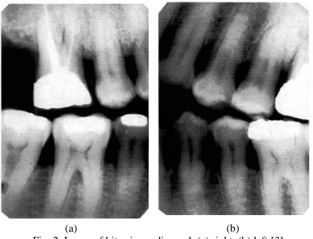
1) Bitewing Radiograph: Bitewing radiographs show
(a) (b) Fig. 2 Image of bitewing radiograph (a) right, (b) left [3]
2) Periapical Radiograph: Periapical radiographs show
the complete tooth from crown to the end of the root where the tooth is anchored in the jaw.
(a) (b)
Fig. 3 Image of periapical radiograph (a) bisected angle, (b) paralleling technique [3]
3) Panoramic radiograph: It shows all the teeth both in upper and lower jaws on a single radiograph.
Fig. 4 Image of panoramic radiograph [3]
The identification of dental caries on the panoramic image is less favorable than that on bitewing or periapical [6]-[15], because:
• It is difficult to distinguish and recognize the objects contained in the image caused by the border of each object is not clearly visible.
• Grayish color differences were not so significant between the borders of dental caries with the boundary edge and element of tooth structure such as enamel, dentin and pulp in the panoramic grayscale image.
Panoramic image requires an image processing that could generate sharper and clear images or improve the quality of information contained in the image so that it can be visually interpreted better [16].
The image enhancement process in each iteration stage can display caries objects clearly. This process will identify dental caries more easily. It will help dental practitioners to identify caries also easily. This research aims to develop some algorithm of the mMG method in identifying dental caries based using digital panoramic dental x-ray images. mMG method is a method to increase the intensity of the boundary edges of objects in an image so that each object which contained in the image can be seen clearly and making it easier to observe [17].
II. MATERIALS AND METHOD
In building a processing system for detecting dental caries toward the image of panoramic dental X-ray of patients with dental caries is needed a research method comprising the steps of cropping and mMG (Fig. 5).
Fig. 5. Steps of process
A. The Original Image
The original image of our data-set was captured by Pantos DG XP production of BlueX Italia. There is a total of 225 grayscale images, in a standard size of 2776×1330 pixel in the data set, which is in the form of *.png format (Fig.6).
Fig. 6 One of the original image data-set
B. Cropping
At the image, Panoramic Dental X-Ray has areas that are not required for subsequent processing. To eliminate these areas in order to facilitate the determination of dental caries in teeth, it needs to be cropping on the image of the teeth.
)
(
-)
(
A
⊕
B
A
Θ
B
Cropping Algorithm is carried out as follow:Cropping Algorithm
Input: Image(x,y) Output: A(x,y)
Initialization
Get lin1, col1, lin2, col2
A(x,y) = Image(lin1:lin2, col1: col2)
The cropping process results can be seen in Fig. 7.
(a)
(b)
(c)
Fig. 7. The process of image acquisition (a) initial coordinate point is at upper left (upper right of the patient position /[R]ight), (b) initial coordinate point is at lower left (Under right of the patient position/[L]eft), (c) image cropping result
The image result of cropping program is shown in Fig. 8.
(a)
(b)
Fig. 8 Cropping image data-set (a) all teeth, (b) one teeth
C. mMG Method
mMG method is a method to increase the intensity of the boundary edges of objects in an image so that each object which contained in the image can be seen clearly and making it easier to observe [23]. Well known mechanisms which are used in mMG method in the image processing are morphology dilation and morphology erosion as well as developing multiple morphology gradient algorithm.
D. Output Image
Output image which is produced will clarify the borders of each object in the image, making it easier for a dentist in the examination to identify dental caries.
III.RESULTSANDDISCUSSION
MMG method is a method that works to improve the image quality of radiology equipment. The imagery used is a panoramic image of dental x-ray as the input image.
Before the image is processed by mMG method, the first area that is not needed in the image is removed by cropping. The amount of in-cropping areas can be freely determined in accordance with the need to be processed.
mMG perform processing method based on the algorithm process that consists of several elements. Encryption elements that form algorithm consists of:
(1) Gradient: Morphology gradient serves to increase
the intensity of the edge forming the objects contained in the image [23]. This process consists of
• Dilation morphology subtracted with erosion morphology:
w
A
mv
=
max(max(
))
Fig. 9 Stages of morphological gradient process in (1)
• Dilation Morphology subtracted with erosion morphology image cropping or image cropping substracted with erosion morphology.
A
-
(
A
Θ
B
)
(2)Fig. 10 Stages of Morphological Gradient Process in (2)
(2) Multiplier Value (mv): Multiplier value is a constant value for the increase in the value of the image pixel. Multiplier value is obtained from the highest value of pixels of the image divided by the bit depth (color space pixels). The formula which is used to obtain mv is as follows:
(3)
with w is bit depth
(3)Threshold (T): Thresholding an image is a special type of quantization that separates the pixel values in two classes, depending upon a given threshold value q that is usually constant. The threshold operation maps all pixels to one of two fixed intensity values of 0 or 1. The segmentation model of thresholding methods is simply formulated as [24], [25].
≥
<
=
q
A
q
A
A
T
1,
0,
)
(
(3)with 0 < q
≤
Amax.There are two sub-processes in mMG image processing, that is:
• Establishing a boundary, on each object in the image. • Performing edge sharpening on each object contained
in the image.
From the configuration of elements described above, then it is obtained 3 (three) algorithms that can be used in the method of mMG.
A. Normal mMG Algorithm
Normal mmHg Algorithm multiplying the whole pixel which is resulted from morphological gradient (dilation
morphology subtracted by erosion morphology) with mv. The algorithm is as follows:
Normal mMG Algorithm
Input: A(x,y) Output: mMG(x,y)
Initialization
B = structure element (A) Get mv
DmE = (A
⊕
B) – (AΘ
B)mMG = DmE * mv
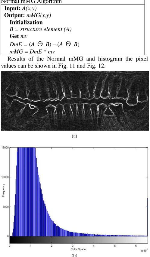
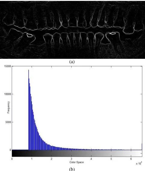
Results of the Normal mMG and histogram the pixel values can be shown in Fig. 11 and Fig. 12.
(a)
(b)
Fig. 11 Normal mMG algorithm with all teeth (a) result image, (b) histogram
(b)
Fig. 12 Normal mMG Algorithm with one teeth (a) Result Image, (b) Histogram
It is shown from Fig. 11 (a) and Fig. 12 (a) that the boundary edges of each object in the image is thicker, so that the objects contained in the image can be seen clearly. In the histogram, it is shown that the values of gray (whitish) level were made higher, so the noise would be intensified. This noise occurs due to the high value of gray level for all pixels multiplied by mv.
B. Enhancement mMG Algorithm
MMG Enhancement Algorithm only multiplies pixel values of the results of the morphological gradient (dilation - erosion) which greater than or equal to T against mv algorithm as follows:
Enhancement mMG Algorithm
Input: A(x,y) Output: mMG(x,y)
Initialization
B = structure element (A) Get mv, T
DmE = (A
⊕
B) – (AΘ
B) for i = 1 to x dofor j = 1 to y do
if DmE(i,j)
≥
T then mMG(i,j) * mv end forend for
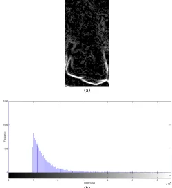
The result of mMG Enhancement and the histogram of pixel value can be seen in Fig. 13 and Fig. 14.
(a)
(a)
(b)
Fig. 13 Enhancement mMG algorithm with all teeth (a) result image, (b) histogram
(a)
(b)
Fig. 14 Enhancement mMG algorithm with one tooth (a) result image, (b) histogram
From Fig. 13 (a) and Fig. 14 (a) it is shown that the boundary edges of each object in the image is thicker so that the objects contained in the image can be seen clearly. In the histogram, it is shown that the gray (whitish) level values increments with Enhancement mMG Algorithm were less prominent than those with Normal mMG Algorithm so that the noise that occurs become less because not all pixels multiplied by mv, but only the pixels of value greater than or equal to T.
C. Smooth mMG Algorithm
Smooth mMG Algorithm
Input: A(x,y) Output: mMG(x,y)
Initialization Get mv, T
SmE = A – (A
Θ
B) for i = 1 to x dofor j = 1 to y do
if SmE(i,j)
≥
T then mMG(i,j) * mv end forend for
The result of mMG Smooth and the histogram of pixel value can be seen in Fig. 15 and Fig. 16 below.
(a)
(b)
Fig. 15 Smooth mMG Algorithm with all teeth (a) result image, (b) histogram
(a)
(b)
Fig. 16 Smooth mMG algorithm with one tooth (a) result image, (b) histogram
It is shown from Fig. 15 (a) and Fig. 16 (a) that the boundary edges of each object in the image is thinner, so that the objects contained in the image is a separate and clearly visible. From the histogram, it is shown that the value of gray level is high (whitish). It is reduced from the normal MMG and MMG enhancement so that the noise become less prominent because not all pixels multiplied by mv, but only the pixels of value greater or equal to T.
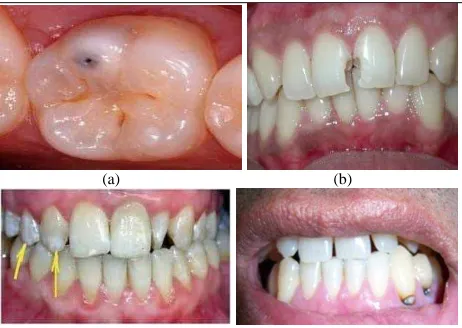
After being examined by two (2) dentist, then it was obtained the results as shown in the diagram in Fig. 17.
Fig. 17 Comparison between the original image and mMG image processing result
IV.CONCLUSIONS
This paper describes the results of digital image processing on the image of Panoramic Dental X-Ray. Panoramic image processed is an image that comes from Radiography Section of Dr. M.Djamil Hospital, Padang-Indonesia. A total of 225 files in the format of * .png image is used in this processing. File image processing algorithms implementing mMG Normal, and Smooth Enhancement mMG on Multiple Morphological Gradient methods (mMG). Image processing results of the three algorithms were examined by two dentists. The results of image processing are very helpful in identifying objects contained in the panoramic image, especially in detecting cavities.
ACKNOWLEDGMENT
REFERENCES
[1] Ryan L.Q. “Dental Caries: A Current Understanding and Implications” Journal of Nature and Science (JNSCI), 1 (1) :e27, 2015 . pp1-5.
[2] Heymann HO, Swift EJ, Ritter AV. Sturdevant's Art and Science of Operative Dentistry, 6th ed. Mosby: St. Louis 2013.
[3] SV Tikhe, AM Naik, SD Bhide, T Saravanan, KP Kaliyamurthie, "Algorithm to Identify Enamel Caries and Interproximal Caries Using Dental Digital Radiographs", IEEE 6th International
Conference on Advanced Computing (IACC), 2016, pp. 226-228.
[4] Ahmed El-Rafei, Tobias Engelhorn (auth.), João Manuel R. S. Tavares, R. M. Natal Jorge (eds.), Computational Vision and
Medical Image Processing: Recent Trends, Springer Netherlands,
ed.1, 2011, pp. 175-190.
[5] Whaites E, Essentials of Dental Radiography and Radiology, Churchill Livingstone, ed 4th, 2003.
[6] Akarslan ZZ, Akdevelioglu M, Gungor K, Erten H, "A comparison of the diagnostic accuracy of bitewing, periapical, unfiltered and filtered digital panoramic images for approximal caries detection in posterior teeth", Dentomaxillofacial Radiol The British Institute of Radiology, 37:458–463, 2008.
[7] Kamburoglu K, Kolsuz E, Murat S, Yüksel S, Ozen T, "Proximal caries detection accuracy using intraoral bitewing radiography, extraoral bitewing radiography and panoramic radiography", Dentomaxillofacial Radiol The British Institute of Radiology, 41:450-459, 2012.
[8] Hoseini Zarch SH, Javadian Langaroodi A, Shafagh Motlagh M, "Comparison between Two Digital Panoramic Radiography Techniques for Proximal Caries Detection", J Dent Mater Tech, 2(2): 54-58, 2013.
[9] Abdinian M, Razavi SM, Faghihian R, Samety AA, Faghihian E, "Accuracy of Digital Bitewing Radiography versus Different Views of Digital Panoramic Radiography for Detection of Proximal Caries", Journal of Dentistry, 12(4):290-297, 2015.
[10] Sabarinathan KM, Mahalakshmi B, Shoba S, Vidhya PG, Siva K, Dhanesh Kumar G, Natarajan Vijayarangan, "Identification of Tooth Decay in Panoramic X-ray using Image Processing", Australian Journal of Basic and Applied Sciences, 9(6):60-64, 2015.
[11] Tafakhori Z, Khazaei M, Afshari Poor A. "Accuracy of Digital Panoramic Imaging in Detection of Proximal Caries in Posterior Teeth", Sadra Med Sci J, 4(2): 99-106, 2016.
[12] Terry GL, Noujeim M, Langlais RP, Moore WS, Prihoda TJ, "A clinical comparison of extraoral panoramic and intraoral radiographic modalities for detecting proximal caries and visualizing
open posterior interproximal contacts", Dentomaxillofacial Radiology, 45(4): 20150159, 2016.
[13] Valizadeh S, Rahimian S, Balali M, Azizi Z, "Effect of Zooming, Colorization, and Contrast Conversion on Proximal Caries Detection", Avicenna Journal of Dental Research. 2016 Jul (inpress). [14] Mohtavipour ST, Javadzadeh Haghighat A, "Comparison of digital panoramic and bite-wing radiography in proximal caries detection of molar teeth", J Isfahan Dent Sch, 11(6):531-533, 2016.
[15] SM Metev and V P Veiko, Laser Assisted Microtechnology, 2nd ed., R. M. Osgood, Jr., Ed. Berlin, Germany: Springer-Verlag, 1998. [16] Madenda, S, Pengolahan Citra & Video Digital, Penerbit Erlangga,
Jakarta, 2015.
[17] Jufriadif N, Johan H, Sarifuddin M, Eri Prasetio W," Identification of the Proximal Caries of Dental X-Ray Image with Multiple Morphology Gradient Method", International Journal on Advanced Science, Engineering and Information Technology, 6(3):343-346, 2016.
[18] Li X, Abaza A, Nassar DE, and Ammar H, “Fast And Accurate Segmentation of Dental X-Ray Records”, Journal of Engineering and Technology, 2(8):688-697, 2005.
[19] Julius S., Jufriadif N., “Infiltrate Object Extraction in X-ray Image
by using Math-Morphology Method and Feature Region Analysis”,
International Journal on Advanced Science, Engineering and Information Technology, 6(2):239-244, 2016.
[20] Eyad Haj Said, Gamal Fahmy, Diaa Nassar, and Hany Ammar,
“Dental X-ray Image Segmentation”, International Journal on
Computer Science and Electrical Engineering, 5(4):175-193, 2006. [21] Sabarinathan KM, Mahalakshmi B, Shoba S, Vidhya PG, Siva K,
Dhanesh Kumar G, Natarajan V, “Identification of Tooth Decay in Panoramic X-ray using Image Processing”, Australian Journal of Basic and Applied Sciences, 9(6):60-64, 2015.
[22] Chen J, Bai G, Liang S, Li Z, Automatic Image Cropping : A Computational Complexity Study, The IEEE Conference on Computer Vision and Pattern Recognition (CVPR), Computer Vision Foundation (CVF) Las Vegas. pp.507-515, 2016.
[23] Soille P, Morphological Image Analysis: Principles and
Applications, 2nd edition, Springer-Verlag Berlin Heidelberg, 2004.
[24] Burger W, Burge MJ, Digital Image Processing, ed. 2nd, Springer,
2016:56.
![Fig. 7. The process of image acquisition (a) initial coordinate point is at upper left (upper right of the patient position /[R]ight), (b) initial coordinate point is at lower left (Under right of the patient position/[L]eft), (c) image cropping result](https://thumb-us.123doks.com/thumbv2/123dok_us/10048673.1991316/3.595.42.283.162.708/acquisition-initial-coordinate-position-coordinate-patient-position-cropping.webp)