Design of Mobile 4G Gateway Based on
Zigbee Wireless Sensor Network
https://doi.org/10.3991/ijoe.v14i11.9518
Bo Qiu
ChangJiang Institute of Technology, Wuhan, China [email protected]
Abstract—To realize the design of mobile 4G gateway of ZigBee wireless sensor network (WSN), a scheme of wireless remote monitoring based on ZigBee and general packet radio service (GPRS) WSN gateway system is proposed. The scheme combines the advantages of short distance, low power consumption, low cost and long distance popular communication of ZigBee technology, and uses the system architecture of ZigBee + GPRS + Android. On this hardware platform, the transplantation of Android system and the development of related hardware device drivers are designed and implemented, so as to build the software platform of the system. Based on the software and hardware platform of the system, the related applications are designed and realized according to the function require-ments of the system, and the software and hardware platform and the application program are tested and analyzed. The test results show that the system runs steily and has good performance. To sum up, the hardware platform has the ad-vantages of low energy consumption, high performance and scalability.
Keywords—ZigBee, GPRS, wireless sensor, gateway
1
Introduction
elements of sensor networks. WSN has many types of sensors, and it can detect a vari-ety of parameters, including temperature, humidity, noise, light intensity, and size, speed and direction of moving objects. Therefore, WSN has a wide range of applica-tions. In many cases of monitoring, because of the constraints of conditions, environ-ment and time, it is difficult for the monitoring personnel to enter the monitoring site and monitor directly and efficiently. They need to monitor with the help of electronic equipment that can adapt to various complex environments. In this context, the remote monitoring technology based on WSN has been widely concerned and highly valued by the academic and engineering circles. The emergence of remote monitoring system makes people quickly and effectively know the detailed information needs to be moni-tored under the objective conditions that people can't reach the scene, and make deci-sions quickly through the relevant information obtained, thus saving a lot of time, hu-man and material resources, and greatly improving the efficiency.
At present, wireless remote monitoring based on WSN generally uses ZigBee tech-nology. Because sensor nodes are usually placed in the area where people are incon-venient to reach, energy saving becomes an important index in remote monitoring. ZigBee technology is exactly in line with such requirements. WSN made up of ZigBee technology has the characteristics of simple structure, small size, low cost and so on, which can realize close range wireless connection. In long distance wireless connection, it can ensure the real-time and reliability of data transmission by using the mobile net-work resources such as global system for mobile communication (GSM)/GPRS and code division multiple access, which are constructed and managed by telecom opera-tors. The ZigBee technology and GPRS technology are combined and applied in wire-less remote monitoring, which has universal practicability and broad application pro-spects.
2
Literature review
With the continuous integration and development of mobile Internet technology, the "broadband", "data" and "grouping" of the mobile communication system are the inev-itable trend. The 3G era is getting far away, and 4G has already come. ZigBee WSN is a new bidirectional wireless communication technology with close range, low power loss and low cost. It has an obvious advantage in wireless positioning, data transmis-sion, sensing network and other application fields. Thus, it has become one of the most concerned technologies in the application of the Internet of Things (IoT). However, as ZigBee is essentially a short distance transmission technology, how to acquire and con-trol remote node information is a difficult problem that must be faced.
problem of using ARM processor S3C2440A to realize protocol conversion between networks [2]. Khan et al. (2016) discussed the idea and scheme of network node design and development. Generally, the combination of processor and radio frequency pro-cessing chip or high integration chip system architecture uses single chip or low-end processor. It also uses the embedded software architecture to implement the transmis-sion network function [3]. Mosterman et al. (2016) studied the two means of the design of embedded software. One is the design idea based on the TinyOS operating system, and another is the solution scheme based on the ZigBee protocol stack. TinyOS can quickly develop component-based architecture, which reduces the code volume oper-ating of the sensing network. The system and library functions are written and designed based on structured concepts and execution models. The solution to the ZigBee stack is to transplant ZigBee protocol stack on the microprocessor or on chip system, and then use the application programming interface function to complete the development of application layer [4]. Khan et al. (2016) studied wireless remote monitoring based on WSN. They used the simple structure, small size, and low cost features of WSN composed of ZigBee technology to realize close range wireless connection, which can ensure the real-time and reliability of data transmission [5]. Nellore et al. (2016) dis-cussed the ZigBee technology and gave the composition of the wireless data acquisition system based on ZigBee. Finally, they completed the node acquisition by using CC2430 chip, designed the hardware and software of the main control unit, and realized data acquisition and wireless transmission [6]. Khan et al. (2016) analyzed the new and open wireless interconnection technology - ZigBee technology, combined sensor technol-ogy, ZigBee technology and routing protocol, and constructed a WSN [7]. Shaikh et al. (2016) studied the ARM9 industrial control motherboard as the core unit, used the om-nidirectional vibration sensor, and designed a set of vibration data acquisition system based on WSN by combining with the ZigBee wireless network technology [8].
To sum up, the above research is mainly aimed at the fusion of mobile network and ZigBee network. However, with the continuous upgrading and replacement of mobile Internet technology, the communication rate of 2G and 3G mobile technology is rela-tively low, which cannot meet the need of large throughput. Therefore, based on the above research status, the new generation of mobile 4G and ZigBee heterogeneous net-work fusion equipment is designed, to meet the requirements for expansion, flexible networking, security and reliability of "far and near" technology in the application of IoT.
3
Method
3.1 Heterogeneous network system
composed of a sink node and multiple nodes. The sink node can communicate with the ZigBee module in the gateway; the 4G communication module in the network commu-nications with the 4G mobile network, and the mobile network eventually interconnects with the traditional Internet.
Fig. 1. The heterogeneous network architecture of 4G and ZigBee
Therefore, 4G and ZigBee gateway is the communication interface between the 4G mobile network and the ZigBee sensor network. It is an important device for the fusion of two kinds of networks. It is also one of the key technologies to realize the comple-mentary, stable and reliable operation of the heterogeneous network advantages.
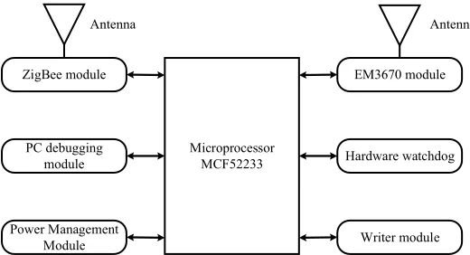
In order to improve the overall performance of the gateway, 32-bit MCF52233 mi-croprocessor is used in the design, the ZigBee wireless module is designed by MC13213 chip, and EM3760 chip is used in the 4G module. The gateway hardware function block diagram is shown in Figure 2.
Fig. 2. The gateway hardware function block diagram
3.2 ZigBee network topology
ZigBee defines two kinds of physical devices that are used in conjunction with each other, namely full function device (FFD) and reduced function device (RFD):
ZigBee network
Aggregation node Node
Gateway
4G base station Internet
Microprocessor MCF52233 ZigBee module
PC debugging module
Power Management Module
EM3670 module
Hardware watchdog
Writer module
FFD can support any kind of topology, which can be used as a router, network co-ordinator or terminal node. It has the function of controller and can communicate with any kind of devices.
RFD, which only supports star topology, cannot be a network coordinator or router, but it can communicate with network coordinator or router.
There are three kinds of device types in the ZigBee agreement: ZigBee network co-ordinator, ZigBee router and ZigBee terminal device. The first two kinds are both FFD, and the terminal device corresponds to RFD.
The ZigBee network coordinator has only one ZigBee network coordinator in each network. The network coordinator is the starting point of establishing the network. It is responsible for starting the network, configuring network member addresses, maintain-ing the network, and maintainmaintain-ing the bindmaintain-ing relationship between nodes, which re-quires most storage space and operational capability. The ZigBee network coordinator must be FFD and have the functions of routing and data forwarding and periodically issuing beacon frames.
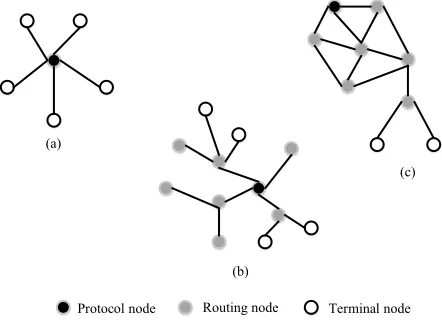
ZigBee Router: the router, similar to the network coordinator, must be FFD. Its main role is to extend the network and to be responsible for data routing. It can also serve as a standby parent node in the network, allowing more devices to connect to the network. Terminal devices: terminal devices can be FFD or RFD. The terminal device can only communicate with the parent node and do not have the ability to become a parent node or router. The specific data routing is all handed over to the parent node and the coordinator or router with routing functions in the network. In general, the specific data routing is used as the edge device of the network and it is connected with the actual monitoring object. ZigBee network topology is shown in Figure 3 below.
Fig. 3. ZigBee network topology
From the above three nodes, ZigBee can form three kinds of network topologies, namely, star network (Star), tree network (Tree) and mesh network (Mesh).
Protocol node Routing node Terminal node (a)
(c)
Star network diagram (Figure 3-a) is the simplest topology, consisting of a network coordinator and multiple terminal devices, but it does not contain router nodes. Star networks are usually used for the occasions with relatively few nodes.
Tree network diagram (Figure 3-b) often uses a beacon-based communication mode, which is connected by a network coordinator and one or more star networks. The router adopts a hierarchical routing strategy to transmit data and control information. The ter-minal device can only communicate with its own parent or sub node, and the other must be complete data transmission through tree routing.
Mesh network diagram (Figure 3-c) is usually formed by a number of FFD con-nected, the communication between them is completely equal, and each node can com-municate with other nodes. The disadvantage of mesh network is the need for more space overhead.
From above, the relationship between the three topologies can be seen, that is, the star network is a subset of the tree network, and the tree net is a subset of the mesh network.
3.3 Wireless communication module
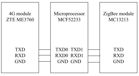
The wireless communication module includes the ZigBee module and the 4G mod-ule. The ZigBee module is designed and realized by using MC13213 chip. The chip is a complete single chip solution proposed for ZigBee technology. It integrates the HCS08MCU and the second generation radio frequency transceiver MC1320x that fol-lows the IEEE802.15.4 standard. It also integrates the complete low power 2.4GHz transceiver, as well as the hardware accelerator used for IEEE802.15.4-MAC and AES security encryption, which is high-density and low-component ZigBee solution. As shown in Figure 4, it is ME3760, MC13213 and master MCF52233 connection dia-gram. The design is connected to UART1 (RXD1) and UART1 (TXD1) of MCF52233 by PTE0 (TXD1) and PTE1 (RXD1), respectively, so as to realize data communication.
Fig. 4. ME3760, MC13213 and master MCF52233 connection diagram
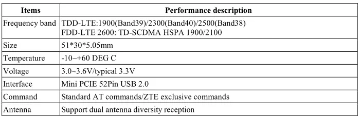
The 4G module is designed with ME3760 chip as the core, and the main technical parameters are shown in Table 1. As shown in Figure 4, MCF52233 communicates to ME3760 data through the serial automatic transmission command. 4G is different from
Microprocessor MCF52233
TXD0 TXD1 RXD0 RXD1 GND GND
ZigBee module MC13213
TXD RXD GND 4G module
ZTE ME3760
the previous three generations in the improvement of speed of data transmission, the transmission of audio signals and the expansion of multimedia services. 4G wireless networks have different data transmission rates in different environments. In indoor, outdoor and dynamic environments, it can support at least downlink 100Mbps and up-link 50Mbps transmission rate, respectively.
Table 1. EM3760 main technical parameters
Items Performance description
Frequency band TDD-LTE:1900(Band39)/2300(Band40)/2500(Band38) FDD-LTE 2600: TD-SCDMA HSPA 1900/2100 Size 51*30*5.05mm
Temperature -10~+60 DEG C Voltage 3.0~3.6V/typical 3.3V Interface Mini PCIE 52Pin USB 2.0
Command Standard AT commands/ZTE exclusive commands Antenna Support dual antenna diversity reception
4
Results
4.1 Selection of software architecture
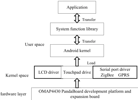
In embedded system software design, there are two architectures which are not based on the operating system and based on the operating system. The system uses the archi-tecture based on the operating system. Compared with the archiarchi-tecture not based on the operating system, that based on the operating system has higher system reliability and real-time performance, and has low development cost and better extensibility. In addi-tion to these advantages, the embedded operating system has the characteristics of small size, strong stability, and unified interface. Because of these features, users only need to develop the corresponding board support packages and upper layer programs. The Android system is chosen as the operating system. The Android system has the charac-teristics of open code source, powerful function and rich and open development re-sources.
Fig. 5. The specific system software architecture
4.2 System function design
The gateway is located in the transmission layer, which is responsible for the data interaction between the user terminal and the sensor nodes. In fact, this is the data in-teraction between the ZigBee communication module and the GPRS wireless commu-nication module. The main function of the ZigBee commucommu-nication module is to collect the data sent from the sensor and transmit to the gateway. In the meanwhile, it also receives instructions transmitted from the gateway. In order to realize these functions, the data processing module is integrated in the ZigBee communication module to ana-lyze the instructions and transmit data, which is mainly aimed at the internal work of ZigBee WSN.
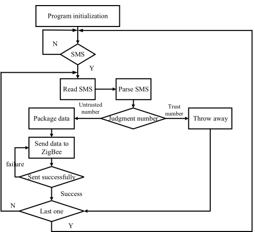
Because the data sent by the ZigBee communication module is divided into query detection data and real-time detection data, an identification bit can be set up in the data header to represent the query detection data or real-time detection data. 0 represents the query detection data, and 1 represents the real-time detection data. When the data is received, the data package is sent to the user terminal if the data is detected; otherwise the data will be displayed on the liquid crystal display (LCD) and whether to send the alarm is judged. The specific work flow is shown in Figure 6 and Figure 7.
Application
System function library
Android kernel
OMAP4430 PandaBoard development platform and expansion board
LCD driver Touchpad drive Serial port driverZigBee GPRS
Transfer Transfer
Load
User space
Kernel space
Fig. 6. The specific work flow of receiving ZigBee data
Fig. 7. The specific work flow of receiving message Program initialization
Listening to the ZigBee serial port
Read data
Analytical data
Judge data type
Display on LCD Encapsulate data
Judgment data value
Encapsulate data
Send SMS
Send success
Send SMS
Send success
Failure Success
Failure Success
Query detection Real-time monitoring
Not out of range
Program initialization
SMS
Read SMS Parse SMS
Judgment number Throw away Package data
Send data to ZigBee
Sent successfully
Last one N
Y
Trust number Untrusted
number
failure
Success N
4.3 Data transmission process
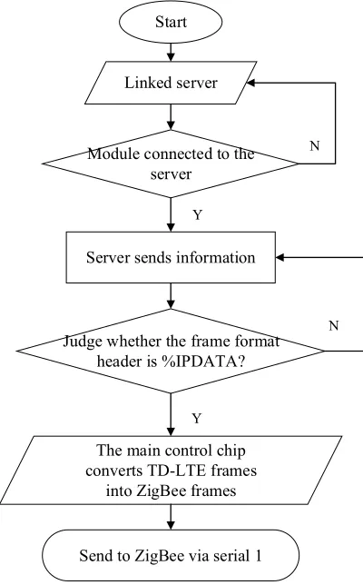
Downlink data workflow: as shown in Figure 8, it is the downlink data workflow of the 4G-ZigBee gateway. The gateway automatically completes dialing, joins the mobile network, and gets the IP address, and then automatically searches the server, connects the server and waits for the server to send instructions. The server is connected with the gateway through the Socket, and the gateway judges whether the frame format head is %IPDATA after receiving data. If not, the server will wait for sending the command; if it is, the TD-LTE frame is converted to the ZigBee frame by the master chip, and the
TD-LTE frame format like %IPDATA: 44
“CC33C33C000000000400010000000000FF000000FF-FF” is converted to 22B16 ZigBee frame format: CC33C33C000000000400010000000-000FF000000FFFF. Af-ter the conversion is completed, the ZigBee data frame is sent to the ZigBee module through serial port 1, and finally sent to the ZigBee slave node through the ZigBee main control module on the gateway.
Fig. 8. The downlink data workflow of the 4G-ZigBee gateway Start
Send to ZigBee via serial 1 Linked server
The main control chip converts TD-LTE frames
into ZigBee frames Module connected to the
server
Judge whether the frame format header is %IPDATA? Server sends information
N
Y
N
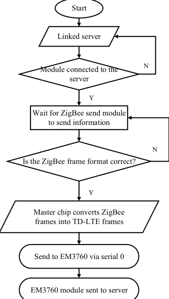
Uplink data workflow: as shown in Figure 9, it is the uplink work flow chart of the 4G-ZigBee gateway. After the gateway is energized, it automatically completes dialing, joins the mobile network, gets the IP address, and waits for the ZigBee module to send data through the serial port 1. The gateway, after receiving the data, determines whether the data is the ZigBee frame format and whether the frame format is correct. If it is not correct, the frame is abandoned, waiting for the ZigBee module to send the data; if it is correct, the master chip will convert it into the frame format that EM3760 can recog-nize, and send it to the EM3760 module through the serial port 0 of single chip micro-computer, and finally the EM3760 module sends it to the cloud server through Socket.
Fig. 9. The uplink work flow chart of the 4G-ZigBee gateway
4.4 Realization of system software functions
Development of system driver: According to the requirements of the system function, a number of external devices are added on the hardware platform. In order to use these external devices, it is necessary to implement their drivers in the Android system envi-ronment. The Android system uses the Linux2.6 kernel, and the system is essentially implemented in the Linux2.6 environment.
Start
Send to EM3760 via serial 0 Linked server
Master chip converts ZigBee frames into TD-LTE frames
Module connected to the server
Is the ZigBee frame format correct? Wait for ZigBee send module
to send information
N
Y
N
Y
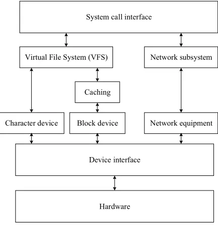
The Linux system has three different types of devices: character device, block device, and network device. The character device is a device that is transmitted in a character in the input and output process. It exists in a file directory in a special file form and can operate on the character device in the manner of ordinary file. Block device stores in-formation in a fixed size block, and each block has its own address and can store, read and write these blocks. Unlike character device and block device, network device is not mapped to special files, but represented by the device data structure. A unique valid name is allocated according to the unix standard, which is oriented to data packets ra-ther than byte-based data streams. The structure of these three devices in the kernel is shown in Figure 10.
Fig. 10. The structure of these three devices in the kernel
In this system, the hardware equipment that needs the driver mainly consists of LCD drive, touch board drive, serial port drive of ZigBee communication module and serial port drive of GPRS wireless communication module. Because it does not necessarily include all the drivers in the Linux kernel release version, some devices can be found based on the hardware manufacturers. The hardware driver development can have the following methods. First, if the corresponding driver is included in the Linux kernel release version, the corresponding configuration options in the kernel are modified. Second, if the kernel release version does not have the driver of the hardware, look for the driver of the similar hardware in the kernel, modify the source code of the similar hardware driver to support the hardware. Third, if the kernel release version has neither the driver of the hardware nor the driver of the similar hardware, it is necessary to add the driver source code of the hardware in the kernel according to the characteristic pa-rameters of the hardware.
System call interface
Virtual File System (VFS) Network subsystem
Caching
Character device Block device Network equipment
Device interface
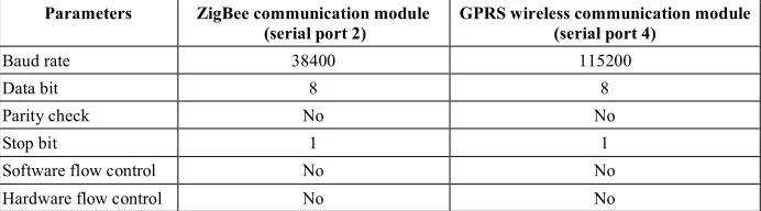
The Linux kernel of OMAP4430PandaBoard development platform has been modi-fied by the development platform manufacturers and can be downloaded directly through the official website. Less serial port connection and simpler communication has become a more common data interface. In this system, the UART1 is used as the command line of the secure digital memory (SD) card, the UART2 is used as the com-munication of the ZigBee comcom-munication module, the UART3 is used as the debug-ging, and the UART4 is used as the communication of the GPRS wireless communica-tion module. In Linux, the serial port is the subtype of teletypes, which needs to con-figure the parameters. The specific parameters are serial number, baud rate, port num-ber, interrupt numnum-ber, and serial port. The serial port 2 and serial port 4 are used here to modify serial number, port number and interrupt number, and the baud rate is set up at the highest. According to the hardware of serial connection, it is necessary to config-ure the parameters of baud rate, data bit, stop bit, parity check and other parameters according to the characteristics of the hardware in the development of the function pro-gram. The configuration of the serial ports 2 and 4 is shown in Table 2.
Table 2. Serial parameters between ZigBee communication module and GPRS wireless com-munication module
Parameters ZigBee communication module
(serial port 2) GPRS wireless communication module (serial port 4)
Baud rate 38400 115200
Data bit 8 8
Parity check No No
Stop bit 1 1
Software flow control No No Hardware flow control No No
Transplantation of Android system: Operation system transplantation is generally divided into three parts: system boot program (Bootloader), operating system kernel and root file system. Bootloader is equivalent to the basic input-output system on the general computer, which is responsible for curing the operating system kernel to Flash to complete the system initialization, and finally submit the control of the system to the operating system. The kernel of the operating system is the management platform after the system is running, which is responsible for the management task. The Bootloader used here is Boot, which is the English abbreviation of Universal Boot Loader. U-Boot has the following features: open source code, support for a variety of embedded operating systems and a variety of processors that are now popular, high stability and flexible functional settings.
The Linux kernel is an abstract layer between hardware and software, which hides concrete hardware details and provides a unified service for the upper layer. The trans-plantation of the kernel is crucial to the transplant of the system. The Linux kernel's migration steps are as follows:
source code is the tree structure, so Makefile is also distributed in the directory tree. The top Makefile file, based on the kernel configuration, recursively calls the Makefile in each subdirectory, generates vmliunix files and kernel modules, and finally com-pletes the kernel compilation work. Here, the top level Makefile needs to be modified, that is, to set up the target platform and cross compiler.
Second, configure SD card information. In order to facilitate the management and protect SD card memory, it needs to be partitioned to separate the U-Boot, kernel, root file system and user area and then add it to the kernel configuration menu.
Third, configure the kernel options. The kernel determines the hardware driver and other functions to be loaded and compiled according to the configuration options. Be-cause the Lunix2.6 kernel provided by the manufacturer has included support for the OMAP4430 chip, it is only necessary to make some modifications on the basis of the related platform configuration.
Fourth, compile the kernel and create the kernel image file and kernel module. The kernel module aims at dynamically adding and deleting some functions and improving the system startup speed. The kernel image command is: make Image and make mod-ules. The generated kernel image file is in the arch/arm/boot directory. If the function or drive in the kernel needs to be set up as a module mode, the kernel module module.ko is generated using the make modules command, and the kernel module files are also stored in the boot directory.
Android source code engineering is divided into three parts: core engineering, exten-sion engineering and package. The core engineering is the foundation for the establish-ment of the Android system, which is stored in the various folders of the root directory, including the support of the basic running of the Android system and the compiling system of the Android system. The extension engineering is an extension of other open source projects, which is stored in the external folder in the root directory and it extends the function of the Android system.
5
Conclusion
In recent years, the development of wireless networks, especially the rapid develop-ment of WSN, has provided powerful technical support for the developdevelop-ment of wireless remote intelligent monitoring. Wireless remote intelligent monitoring technology, which combines wireless communication technology, sensor technology and embedded technology, has great advantages compared with traditional monitoring technology. It has been used in various remote monitoring, including intelligent home and environ-ment monitoring. The latest 4G mobile communication technology has high bandwidth, long distance transmission and other features. The emergence of ZigBee wireless tech-nology has well filled the defects of wireless communication techtech-nology. The key to its success lies in the advantages of rich and convenient applications, easy networking, flexible networking and strong scalability. It is a general trend to design a new gateway to upgrade the two heterogeneous network convergence technologies. The gateway has the characteristics of low cost, high reliability and low power consumption. It not only occupies a status in the field of data acquisition and industrial control, but also has a good application scene and practical application value in other fields, such as intelligent home and public security monitoring.
6
References
[1] Gao, Y., Qin, Z., Feng, Z. (2016). Scalable and reliable IoT enabled by dynamic spec-trum management for M2M in LTE-A. IEEE Internet of Things Journal, 3(6): 1135-1145. [2] Liu, Q., Ma, Y., Alhussein, M. (2016). Green data center with IoT sensing and cloud-assisted
smart temperature control system. Computer Networks, 101: 104-112.
https://doi.org/10.1016/j.comnet.2015.11.024
[3] Khan, F., Jan, S.R., Tahir, M. (2016). Survey: Dealing Non-Functional Requirements at Ar-chitecture Level. VFAST Transactions on Software Engineering, 9(2): 7-13.
https://doi.org/10.21015/vtse.v9i2.410
[4] Mosterman, P.J., Zander, J. (2016). Cyber-physical systems challenges: a needs analy-sis for collaborating embedded software systems. Software & Systems Modeling, 15(1): 5-16.
https://doi.org/10.1007/s10270-015-0469-x
[5] Khan, I., Belqasmi, F., Glitho, R. (2016). Wireless sensor network virtualization: A survey. IEEE Communications Surveys & Tutorials, 18(1): 553-576.
https://doi.org/10.1109/COMST.2015.2412971
[6] Nellore, K., Hancke, G.P. (2016). A survey on urban traffic management system using wire-less sensor networks. Sensors, 16(2): 157. https://doi.org/10.3390/s16020157
[7] Khan, A.A., Rehmani, M.H., Reisslein, M. (2016). Cognitive radio for smart grids: Survey of architectures, spectrum sensing mechanisms, and networking protocols. IEEE Communi-cations Surveys & Tutorials, 18(1): 860-898. https://doi.org/10.1109/COMST.2015. 2481722
[8] Shaikh, F.K., Zeadally, S. (2016). Energy harvesting in wireless sensor networks: A com-prehensive review. Renewable and Sustainable Energy Reviews, 55: 1041-1054.
7
Author
Bo Qiu is with ChangJiang Institute of Technology, Wuhan, 430212, China (e-mail: [email protected]).