© Copyright 2014 Pearson Education, Inc. All rights reserved. This material is protected under all copyright laws as they currently exist.
Responses to Questions
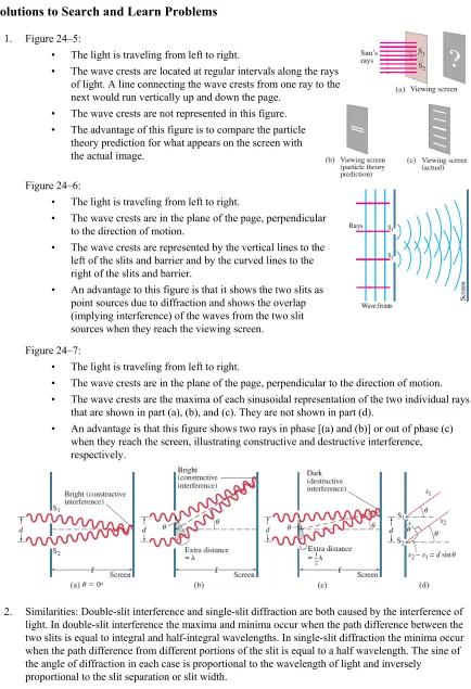
1. Huygens’ principle applies to both sound waves and water waves. Huygens’ principle applies to all waves that form a wave crest. Sound, water, and light waves all can be represented in this way. The maximum or crest of a water wave is its highest point above the equilibrium level of the water, so a wave front can be formed by connecting all of the local maximum points of a wave.
2. A ray shows the direction of propagation of a wave front. If this information is enough for the situation under discussion, then light can be discussed as rays. This is true in particular for geometric optics. Sometimes, however, the wave nature of light is essential to the discussion. For instance, the double-slit interference pattern depends on the interference of the waves and could not be explained by examining light as only rays.
3. The bending of waves around corners or obstacles is called diffraction. Diffraction is most prominent when the size of the obstacle is on the order of the size of the wavelength. Sound waves have much longer wavelengths than do light waves. As a result, the diffraction of sound waves around a corner of a building or through a doorway is noticeable, and we can hear the sound in the “shadow region,” but the diffraction of light waves around a corner is not noticeable because of the very short wavelength of the light.
4. For destructive interference, the path lengths must differ by an odd number of half wavelengths, such as λ/2, 3λ/2, 5λ/2, 7λ/2, etc. In general, the path lengths must differ by λ(m+ ½), where m is an integer. Under these conditions, the wave crests from one ray match up with the wave troughs from the other ray and cancellation occurs (destructive interference).
5. As red light is switched to blue light, the wavelength of the light is decreased. Thus, sind θ=mλ says that θ is decreased for a constant m and d. This means that the bright spots on the screen are more closely packed together with blue light than with red light.
6. The wavelength of light in a medium such as water is decreased when compared to the wavelength in air. Thus, sind θ =mλ says that θ is decreased for a particular m and d. This means that the bright spots on the screen are more closely packed together in water than in air.
7. The reason you do not get an interference pattern from the two headlights of a distant car is that they are not coherent light sources. The phase relationship between the two headlights is not constant—they
have randomly changing phases relative to each other. Thus, you cannot produce zones of destructive and constructive interference where the crests and troughs match up or the crests and crests match up. Also, the headlights are far enough apart that even if they were coherent, the interference pattern would be so tightly packed that it would not be observable with the unaided eye.
8. For a very thin film, there are only a select few distinct visible wavelengths that meet the constructive interference criteria, because the film is only a few wavelengths thick. But for a thick film, there might be many different wavelengths that meet the constructive interference criteria for many different m values. Accordingly, many different colors will constructively interfere, and the reflected light will be white (containing all visible wavelengths).
9. As you move farther away from the center of the curved piece of glass on top, the path differences change more rapidly due to the curvature. Thus, you get higher order interference patterns more closely spaced together. An “air wedge,” as in Fig. 24–33, has equally spaced interference patterns because as the observation point is moved farther from the contact point of the flat piece of glass on top, the path differences change linearly.
10. These lenses probably are designed to eliminate reflected wavelengths at both the red and the blue ends of the spectrum. The thickness of the coating is designed to cause destructive interference for reflected red and blue light. The reflected light then appears yellow-green.
11. The index of refraction of the oil must be less than the index of refraction of the water. If the oil film appears bright at the edge, then the interference between the light reflected from the top of the oil film and that reflected from the bottom of the oil film at that point must be constructive. The light reflecting from the top surface (the air/oil interface) undergoes a 180° phase shift since the index of refraction of the oil is greater than that of air. The thickness of the oil film at the edge is negligible, so for there to be constructive interference, the light reflecting from the bottom of the oil film (the oil/water interface) must also undergo a 180° phase shift. This will occur only if the index of refraction of the oil is less than that of the water: 1.00 < n < 1.33.
12. Radio waves have a much longer wavelength than visible light and will diffract around normal-sized objects (like hills). The wavelengths of visible light are very small and will not diffract around normal-sized objects. Thus diffraction allows the radio waves to be “picked up” even if the broadcasting tower is not visible on a line of sight.
13. You see a pattern of dark and bright lines parallel to your fingertips in the narrow opening between your fingers, due to diffraction.
14. (a) When you increase the slit width in a single-slit diffraction experiment, the spacing of the fringes decreases. The equation for the location of the minima, sin m ,
D
λ
θ= indicates that θ is decreased for a particular m and λ when the width D increases. This means that the bright spots on the screen are more closely packed together for a wider slit.
(b) When you increase the wavelength of light used in a single-slit diffraction experiment, the spacing of the fringes increases. The equation for the location of the minima, sin m ,
D
λ θ=
indicates that θ is increased for a particular m and D when the wavelength increases. This means that the bright spots on the screen are spread farther apart for a longer wavelength. 15. (a) A slit width of 60 nm would produce a central maximum so spread out that it would cover the
because the first minimum would have to satisfy sin 10,
D
λ
θ = ≈ which is not possible. The different wavelengths will all overlap, so the light on the screen will be white. It will also be dim, compared to the source, because it is spread out.
(b) For the 60,000-nm slit, the central maximum will be very narrow, about a degree in width for the blue end of the spectrum and about a degree and a half for the red. The diffraction pattern will not be distinct, because most of the intensity will be in the small central maximum and the fringes for the different wavelengths of white light will not coincide.
16. (a) If the apparatus is immersed in water, then the wavelength of the light will decrease .
n
λ λ ⎛ ′ = ⎞
⎜ ⎟
⎝ ⎠
and the diffraction pattern will become more compact.
(b) If the apparatus is placed in a vacuum, then the wavelength of the light will increase slightly and the diffraction pattern will spread out very slightly.
17. The interference pattern created by the diffraction grating with 104 lines/cm has bright maxima that are more sharply defined and narrower than the interference pattern created by the two slits 10−4 cm apart. The spacing of the bright maxima would be the same in both patterns, but for the grating, each maximum would be essentially the same brightness, while for the two-slit pattern, slit width effects would make the maxima for m > 1 much less bright than the central maximum.
18. (a) The advantage of having many slits in a diffraction grating is that this makes the bright maxima in the interference pattern more sharply defined, brighter, and narrower.
(b) The advantage of having closely spaced slits in a diffraction grating is that this spreads out the bright maxima in the interference pattern and makes them easier to resolve.
19. (a) Violet light will be at the top of the rainbow created by the diffraction grating. Principal maxima for a diffraction grating are at positions given by sin m .
d λ
θ = Violet light has a shorter wavelength than red light so will appear at a smaller angle away from the direction of the horizontal incident beam.
(b) Red light will appear at the top of the rainbow created by the prism. The index of refraction for violet light in a given medium is slightly greater than for red light in the same medium, so the violet light will bend more and will appear farther from the direction of the horizontal incident beam.
20. Polarization demonstrates the transverse wave nature of light and cannot be explained if light is considered as a longitudinal wave or as classical particles.
21. Polarized sunglasses completely block horizontally polarized glare at certain reflected angles and also block unpolarized light by 50%. Regular tinted sunglasses reduce the intensity of all incoming light but don’t preferentially reduce the “glare” from smooth reflective surfaces.
23. If Earth had no atmosphere, then the color of the sky would be black (and dotted with stars and planets) at all times. This is the condition of the sky that the astronauts found on the Moon, which has no atmosphere. If there were no air molecules to scatter the light from the Sun, then the only light we would see would be from the stars, the planets, the Moon, and direct sunlight. The rest of the sky would be black.
24. If the atmosphere were 50% more dense, then sunlight (after passing through the atmosphere) would be much redder than it is now. As the atmosphere increased in density, more and more of the blue light would be scattered away in all directions, making the light that reaches the ground very red. Think of the color of a deep red sunset, but this might be the color even when the sun was at high elevations.
Responses to MisConceptual Questions
1. (a) The width of the fringes is proportional to the wavelength and inversely proportional to the slit spacing. Therefore, since red light has the longer wavelength, red light with small slit spacing will have the largest fringe width.
2. (a) At point A the green laser light is at a maximum. The next maximum (B) occurs when the path difference between the point and each of the two slits is equal to one full wavelength, or 530 nm. The minimum (halfway between points A and B) is the point where the difference in distances is equal to a half wavelength (or 265 nm).
3. (c) The index of refraction in the water droplets varies slightly with wavelength. Therefore, as sunlight passes through the droplets, the light of different frequencies (colors) refracts at slightly different angles.
4. (a) The cause of single-slit diffraction can be difficult to understand. The slit can be divided into a number of individual regions. If the path difference between each pair of regions and a point on the screen is a half wavelength, then destructive interference occurs at that point.
5. (b) It might be common to think that the lines are due to the inability of the eye to focus on the point. However, the lines are due to diffraction of the light as it passes through the very small opening between your fingers.
6. (b) The spreading out of the light is due to diffraction, with diffraction being significant when the slit size is about the same size as the wavelength of light. For visible light, the wavelength is about 5 10× –7 m, which is on the order of the slit width. Therefore, the light will spread out wider than the slit. The height opening, which is 4 orders of magnitude larger than the
wavelength, will have almost no discernible diffraction, so the light will remain about the same height.
7. (d) In Eq. 24–2a the angles of constructive interference are proportional to the wavelength and inversely proportional to the slit width. Therefore, if the slit width and wavelength are changed by the same factor, then the diffraction pattern will not change.
9. (c) It can be difficult to recognize the different scales of length involved with the diffraction of sound versus the diffraction of light. The sound waves of a person’s voice have wavelengths about the same size as a doorway and therefore diffract easily around the corner. The wavelength of light is much smaller, approximately 10–7 m, so light does not diffract around the corner. 10. (c) The CD is made of thinly spaced grooves. As light reflects off of these grooves, the light
interferes in the same way as when it passes through a diffraction grating. Note that the diffraction pattern is the same regardless of the data and/or security on the CD. The bit pattern does not determine the diffraction—just the presence of the thinly spaced grooves.
11. (e) If the film has regions of lower index of refraction on both sides of the film (or higher on both sides), then a phase shift will occur at one surface but not the other. In this case constructive interference will occur when the thickness is ¼ of a wavelength and destructive interference will occur when the thickness is ½ of a wavelength. If the film has a lower index on one side and a higher index on the other, then either no phase shift will occur at either surface or phase shifts will occur at both surfaces. In this case destructive interference occurs when the film has a thickness of ¼ wavelength and constructive interference occurs when the thickness is ½ of a wavelength. Since the indices of refraction are not specified for the surfaces of the film, none of the answers are always true.
12. (b) If two successive polarizers are perpendicular to each other, then light cannot get through. In case 1, the first two polarizers are perpendicular, and in case 2, the last two polarizers are perpendicular. In case 2, no successive polarizers are perpendicular, so some light can pass through.
Solutions to Problems
1. For constructive interference, the path difference is a multiple of the wavelength, as given by Eq. 24–2a. Apply this to the fifth order.
5
7 sin (1.8 10 m)sin 8.6
sin 5.4 10 m
5
d
d m
m
θ
θ= λ → λ= = × − °= × −
2. For constructive interference, the path difference is a multiple of the wavelength, as given by Eq. 24–2a. Apply this to the third order (m= 3).
9
6
3(610 10 m)
sin 3.6 10 m
sin sin 31
m
d θ=mλ → d = λθ = × − = × − °
3. For constructive interference, the path difference is a multiple of the wavelength, as given by Eq. 24–2a. The location on the screen is given by x= tan ,θ as seen in Fig. 24–7(c). For small angles, we have
sinθ ≈tanθ ≈x/ . Adjacent fringes will have Δ =m 1.
1
1 2 2 1
5
7 7
8
14 7
10 sin
( 1) ( 1)
;
(4.8 10 m)(0.085 m)
6.277 m 6.3 10 m 6.50 m
3.00 10 m/s
4.8 10 Hz 6.277 10 m
x m
d m d m x
d
m m m m
x x x x x
d d d d d
d x
c f
λ
θ λ λ
λ λ λ λ λ
λ
λ
−
− −
−
×
= → = → =
+ +
= = → Δ = − = − =
Δ ×
= = = ≈ ×
×
= = = ×
4. For constructive interference, the path difference is a multiple of the wavelength, as given by Eq. 24–2a. The location on the screen is given by x= tan ,θ as seen in Fig. 24–7(c). For small angles, we have
sinθ ≈tanθ ≈x/ . Second order means m = 2.
1 2
1 2
9
4
2 1
2 1 4
sin ; ;
( ) [(720 660) 10 ](2)(1.0 m)
1.935 10 m 0.2 mm (6.2 10 m)
m m
x m
d m d m x x x
d d d
m m
x x x
d
λ λ
λ
θ λ λ
λ λ −
− −
= → = → = = = →
− − ×
Δ = − = = = × ≈
×
This justifies using the small angle approximation, since x .
5. For destructive interference, the path difference is as follows.
(
)
(
) (
)
(
)
1 1
2 2
1 1
2 2
(4.5 cm)
sin sin (0.60), 0,1, 2, 3, .
(7.5 cm)
m m
d m m m
d
λ
θ = + λ → θ = + = + = + = …
The angles for the first three regions of complete destructive interference are calculated.
( )
( )
( )
1 1 1
0 2
1 1 1
1 2
1 1 1
2 2
sin 0 (0.60) sin 0.30 17.46 17
sin 1 (0.60) sin 0.90 64.16 64
sin 2 (0.60) sin 1.50 impossible
θ θ θ
− −
− −
− −
⎡ ⎤
= ⎣ + ⎦= = ° ≈ °
⎡ ⎤
= ⎣ + ⎦= = ° ≈ °
⎡ ⎤
= ⎣ + ⎦= =
There are only two regions of destructive interference, at 17° and 64 .°
6. The slit spacing and the distance from the slits to the screen are the same in both cases. The distance between bright fringes can be taken as the position of the first bright fringe (m= 1) relative to the central fringe. We indicate the lab laser with subscript 1 and the laser pointer with subscript 2. For constructive interference, the path difference is a multiple of the wavelength, as given by Eq. 24–2a. The location on the screen is given by x= tan ,θ as seen in Fig. 24–7(c). For small angles, we have sinθ ≈tanθ≈x/ .
1 2
1 2
1
2 2 2
1
sin ; ;
5.14 mm
(632.8 nm) 650.52 nm 651 nm 5.00 mm
x m
d m d m x x x
d d d
d
x x
x
λ λ
λ
θ λ λ
λ λ
= → = → = = = →
= = = = ≈
7. For constructive interference, the path difference is a multiple of the wavelength, as given by Eq. 24–2a. The location on the screen is given by x= tan ,θ as seen in Fig. 24–7(c). For small angles, we have
sinθ ≈tanθ ≈x/ .
9
4 3
(680 10 m)(3)(2.8 m)
sin 1.5 10 m
38 10 m
x m
d m d m d
x
λ
θ λ λ − −
−
×
= → = → = = = ×
×
8. Using a ruler on Fig. 24–9a, the width of 18 fringes is found to be about 25 mm. For constructive interference, the path difference is a multiple of the wavelength, as given by Eq. 24–2a. The location on the screen is given by x= tan ,θ as seen in Fig. 24–7(c). For small angles, we have
sinθ ≈tanθ ≈x/ .
4
7
(1.7 10 m)(0.025 m)
sin 6.4 10 m
(18)(0.37 m)
x dx dx
d m d m
m m
9. For constructive interference, the path difference is a multiple of the wavelength, as given by Eq. 24–2a. The location on the screen is given by x= tan ,θ as seen in Fig. 24–7(c). For small angles, we have
sinθ ≈tanθ ≈x/ . For adjacent fringes, Δ =m 1.
9
5
sin
(633 10 m)(3.3 m)
(1) 0.0307 m 3.1 cm
(6.8 10 m)
x m
d m d m x
d
x m
d
λ
θ λ λ
λ −
−
= → = → = →
×
Δ = Δ = = =
×
10. For constructive interference, the path difference is a multiple of the wavelength, as given by Eq. 24–2a. The location on the screen is given by x= tan ,θ as seen in Fig. 24–7(c). For small angles, we have
sinθ ≈tanθ ≈x/ .
9
6
(633 10 m)(1)(5.0 m)
sin 9.0 10 m
(0.35 m)
x m
d m d m d
x
λ
θ = λ → = λ → = = × − = × −
11. The 180° phase shift produced by the glass is equivalent to a path length of 1
2λ. For constructive interference on the screen, the total path difference is a multiple of the wavelength:
1
(
1)
max max
2λ+dsinθ =mλ, m=0, 1, 2, → dsinθ = m−2 λ, m=1, 2, We could express the result as
(
1)
max 2
sin , 0, 1, 2, .
d θ = m+ λ m=
For destructive interference on the screen, the total path difference is
1
(
1)
min min
2λ+dsinθ = m+2 λ, m=0, 1, 2, → dsinθ =mλ, m=0, 1, 2, Thus the pattern is just the reverse of the
usual double-slit pattern. There will be a dark central line instead of a bright central
maximum. Every place there was a bright fringe will now have a dark line, and vice versa.
Figure 24–10 is reproduced here, and immediately to the right is the pattern that would appear from the situation described by this problem. Notice that maxima have changed to minima, and vice versa.
12. We equate the expression from Eq. 24–2a for the second-order blue light to Eq. 24–2b, since the slit separation and angle must be the same for the two conditions to be met at the same location.
(
)
(
)
1
b 2
1 2
sin (2)(480 nm) 960 nm; sin , 0, 1, 2,
960 nm 1920 nm; 1 640 nm
2 384 nm
d m d m m
m m m
m
θ λ θ λ
λ λ λ
λ
′ ′
= = = = + =
′+ = ′= 0 → = ′= → =
′ = → =
The only one visible is 640 nm. 384 nm is near the low-wavelength limit for visible light.
13. For constructive interference, the path difference is a multiple of the wavelength, as given by Eq. 24–2a. The location on the screen is given by x= tan ,θ as seen in Fig. 24–7(c). For small angles, we have
sinθ ≈tanθ ≈x/ . For adjacent fringes, Δ =m 1.
9
3 3
sin
(544 10 m)(4.0 m)
(1) 2.2 10 m
(1.0 10 m)
x m
d m d m x
d
x m
d
λ
θ λ λ
λ −
− −
= → = → = →
×
Δ = Δ = = ×
×
14. We have the same setup as in Example 24–3, so the two slits are 0.50 mm apart, and the screen is 2.5 m away. We use Eq. 24–21 with the small-angle approximation as described in that example, and solve for the wavelength.
4 3
7 (5.0 10 m)(2.9 10 m)
sin 5.8 10 m
(1)(2.5 m)
x dx
d d m
m
θ = = λ → λ= = × − × − = × −
From Fig. 24–12, that wavelength is yellow.
15. An expression is derived for the slit separation from the data for the 480-nm light. That expression is then used to find the location of the maxima for the 650-nm light. For constructive interference, the path difference is a multiple of the wavelength, as given by Eq. 24–2a. The location on the screen is given by x= tan ,θ as seen in Fig. 24–7(c). For small angles, we have sinθ ≈tanθ≈x/ .
1 1 1
2 2 2 2
2 1
1 1 1 1 1
sin
(650 nm)(2)
(16 mm) 14.44 mm 14 mm
/ (480 nm)(3)
m
x m m
d m d m d x
x x d
m m
x x
m x m
λ
λ λ
θ λ λ
λ λ
λ λ
= → = → = = → = →
= = = = ≈
16. The presence of the water changes the wavelength according to Eq. 24–1, so we must change λ to
/ .
n n
λ =λ For constructive interference, the path difference is a multiple of the wavelength, as given by Eq. 24–2a. The location on the screen is given by x= tan ,θ as seen in Fig. 24–7(c). For small angles, we have sinθ≈tanθ≈x/ . Adjacent fringes will have Δ =m 1.
1
1 2
9
2 1 5
3 3
10
( 1)
sin ; ;
( 1) (470 10 m)(0.400 m)
(1.33)(6.00 10 m) 2.356 m 2.4 10 m
n
n n
n n n
m m
x m
d m d m x x x
d d d
m m
x x x
d d d nd
λ λ λ
θ λ λ
λ λ λ λ −
−
− −
×
+
= → = → = = = →
+ ×
Δ = − = − = = =
×
= ≈ ×
17. To change the center point from constructive to destructive interference, the phase shift produced by inserting the plastic must be equivalent to half a wavelength. The wavelength of the light is shorter in the plastic than in the air, so the number of wavelengths in the plastic must be ½ greater than the number in the same thickness of air. The number of wavelengths in the distance equal to the thickness of the plate is the thickness of the plate divided by the appropriate wavelength.
plastic 1
plastic air plastic 2
plastic
plastic
( 1)
680 nm
570 nm 2( 1) 2(1.60 1)
tn
t t t t
N N n
t n
λ λ λ λ λ
λ
− = − = − = − = →
= = =
18. We find the speed of light from the index of refraction, υ=c n/ . We calculate the % difference using the red as the standard. Note that answers will vary due to differences in reading the graph.
red blue red blue blue red
red blue
red
( ) ( ) (1.615 1.640)
0.015 1.5% less (1.640)
c c
n n n n
n c
n
υ υ
υ
⎡⎛ ⎞ ⎛ ⎞⎤ −
⎢⎜ ⎟ ⎜ ⎟⎥
− =⎣⎝ ⎠ ⎝ ⎠⎦= − = − = − =
⎛ ⎞
⎜ ⎟
⎝ ⎠
19. We find the angles of refraction in the glass from Snell’s law, n1sinθ1=n2sin .θ2
2,450 2,450
2,700 2,700
2,700 2,450
(1.00)sin 65.00 (1.4831)sin 37.67 (1.00)sin 65.00 (1.4754)sin 37.90
37.90 37.67 0.23
θ θ
θ θ
θ θ
° = → = °
° = → = °
− = ° − ° = °
20. We use Snell’s law for the refraction at the first surface, entering the prism. The lower wavelength has the higher index of refraction. The indices of refraction are found from Fig. 24–14.
air
,455 ,455
,642 ,642
sin sin ;
(1.00)sin 45 (1.64)sin 25.54 (1.00)sin 45 (1.62)sin 25.88
a b
b b
b b
n θ n θ
θ θ
θ θ
=
° = → = °
° = → = °
We find the angle of incidence at the second surface, leaving the prism, from the second diagram.
,455 ,455
,642 ,642
(90 ) (90 ) 180
60.00 25.54 34.46 60.00 25.88 34.12
b c
c b
c b
A A
A
θ θ
θ θ
θ θ
° − + ° − + = °
= − = ° − ° = °
= − = ° − ° = °
Use Snell’s law again for the refraction at the second surface.
air
,455 ,455 1
,642 ,642 2
sin sin
(1.64)sin 34.46 (1.00)sin 68.1 (1.62)sin 34.12 (1.00)sin 65.3
c d
d d
d d
n θ n θ
θ θ θ
θ θ θ
=
° = → = = °
° = → = = °
The values may vary slightly from differences in reading the graph.
21. We use Eq. 24–3a to calculate the angular distance from the middle of the central peak to the first minimum. The width of the central peak is twice this angular distance.
9
1 1
1 1 3
1
680 10 m
sin sin sin 0.9168
0.0425 10 m 2 2(0.9168) 1.834 1.8
D D
λ λ
θ θ
θ θ
−
− −
−
⎛ × ⎞
⎛ ⎞
= → = ⎜ ⎟= ⎜⎜ ⎟⎟= °
⎝ ⎠ ⎝ × ⎠
22. The angle from the central maximum to the first dark fringe is equal to half the width of the central maximum. Using this angle and Eq. 24–3a, we calculate the wavelength used.
1 1
1 2 2
3 4
1 1
(28.0 ) 14.0
sin Dsin (2.60 10 mm) sin (14.0 ) 6.29 10 mm 629 nm
D
θ θ
λ
θ λ θ − −
= Δ = ° = °
= → = = × ° = × =
23. We set the angle to the first minimum equal to half of the separation angle between the dark bands. We insert this angle into Eq. 24–3a to solve for the slit width.
1 1
2 2
6
(51.0 ) 25.5
440 nm
sin 1022 nm 1.0 10 m
sin sin 25.5
D D
θ θ
λ λ
θ
θ −
= Δ = ° = °
= → = = = ≈ ×
°
24. We find the angle to the first minimum using Eq. 24–3a. The distance on the screen from the central maximum is found using the distance to the screen and the tangent of the angle. The width of the central maximum is twice the distance from the central maximum to the first minimum.
9
1 1
1 1 3
3
1 1
3 3
1
450 10 m
sin sin sin 0.02578
1.0 10 m tan (6.0 m) tan 0.02578 2.70 10 m 2 2(2.70 10 m) 5.4 10 m 0.54 cm
D D
x
x x
λ λ
θ θ
θ
−
− −
−
−
− −
⎛ × ⎞
⎛ ⎞
= → = ⎜ ⎟= ⎜⎜ ⎟⎟= °
⎝ ⎠ ⎝ × ⎠
= = ° = ×
Δ = = × = × =
25. We find the angle to the first minimum using Eq. 24–3a. The distance on the screen from the central maximum is found using the distance to the screen and the tangent of the angle. The width of the central maximum is twice the distance from the central maximum to the first minimum.
9
1 1
1 1 5
2
1 1
2 2
1
558 10 m
sin sin sin 0.9187
3.48 10 m tan (2.30 m) tan 0.9187 3.688 10 m
2 2(3.688 10 m) 7.38 10 m
D D
x
x x
λ λ
θ θ
θ
−
− −
−
−
− −
⎛ × ⎞
⎛ ⎞
= → = ⎜ ⎟= ⎜⎜ ⎟⎟= °
⎝ ⎠ ⎝ × ⎠
= = ° = ×
Δ = = × = ×
26. (a) We use Eq. 24–3b, using m= 1, 2, 3,… to calculate the possible diffraction minima when the wavelength is 0.50 cm.
1
m m
1 1
1 2
1 1
3 4
sin sin
1 0.50 cm 2 0.50 cm
sin 18.2 sin 38.7
1.6 cm 1.6 cm
3 0.50 cm 4 0.50 cm
sin 69.6 sin no solution
1.6 cm 1.6 cm
m
D m
D
λ
θ λ θ
θ θ
θ θ
−
− −
− −
⎛ ⎞
= → = ⎜⎝ ⎟⎠
⎛ × ⎞ ⎛ × ⎞
= ⎜ ⎟= ° = ⎜ ⎟= °
⎝ ⎠ ⎝ ⎠
⎛ × ⎞ ⎛ × ⎞
= ⎜ ⎟= ° = ⎜ ⎟ →
⎝ ⎠ ⎝ ⎠
(b) We repeat the process from part (a) using a wavelength of 1.0 cm.
θ1 sin−1 1 1.0 cm1.6 cm 38.7 θ2 sin−1 2 1.0 cm1.6 cm no real solution
⎛ × ⎞ ⎛ × ⎞
= ⎜ ⎟= ° = ⎜ ⎟=
⎝ ⎠ ⎝ ⎠
The only diffraction minimum is at 39°.
(c) We repeat the process from part (a) using a wavelength of 3.0 cm.
1 sin 1 1 3.0 cm no real solution 1.6 cm
θ = − ⎛ × ⎞=
⎜ ⎟
⎝ ⎠
There are no diffraction minima.
27. (a) There will be no diffraction minima if the angle for the first minimum is greater than 90°. We set the angle in Eq. 24–3a equal to 90° and solve for the slit width.
sin
sin 90 D
D
λ λ
θ= → = = λ
°
(b) For no visible light to exhibit a diffraction minimum, the slit width must be equal to the shortest visible wavelength.
D=λmin = 400 nm
28. The first bright region occurs at sin 3 . 2D
λ
θ ≈ We then find the distance on the screen from the central maximum by multiplying the distance to the screen by the tangent of the angle.
9
1 1
max 6
1
3 3(620 10 m)
sin sin 14.17
2 2(3.80 10 m) tan (10.0 m) tan (14.17 ) 2.52 m
D
x
λ θ
θ
−
− −
−
⎡ × ⎤
⎛ ⎞
= ⎜⎝ ⎟⎠= ⎢ ⎥= °
×
⎢ ⎥
⎣ ⎦
= = ° =
29. The angle from the central maximum to the first bright maximum is half the angle between the first bright maxima on either side of the central maximum. The angle to the first maximum is about halfway between the angles to the first and second minima. We use Eq. 24–3b, setting m=3/2, to calculate the slit width, D.
1 1
1 2 2
m
1 (32 ) 16
(3/2)(633 nm)
sin 3445 nm 3.4 m
sin sin16 m
D m D
θ θ
λ
θ λ μ
θ = Δ = ° = °
= → = = = ≈
°
30. (a) For vertical diffraction we use the height of the slit (1.5 μm) as the slit width in Eq. 24–3a to calculate the angle between the central maximum to the first minimum. The angular separation of the first minima is equal to twice this angle.
9
1 1
1 1 6
1
780 10 m
sin sin sin 31.3
1 5 10 m 2 2(31.3 ) 63
D D
λ λ
θ θ
θ θ
−
− − ×
= → = = = °
. ×
Δ = = ° ≈ °
(b) To find the horizontal diffraction we use the width of the slit (3.0 μm) in Eq. 24–3a.
9
1 1
1 1 6
1
780 10 m
sin sin sin 15.07
3.0 10 m 2 2(15.07 ) 30
D D
λ λ
θ θ
θ θ
−
− −
−
×
= → = = = °
×
Δ = = ° ≈ °
Note that the 30°has 2 significant figures.
31. The path difference between the top and bottom of the slit for the incident wave is Dsin .θi The path difference between the top and bottom of the slit for the diffracted wave is sin .D θ Therefore, the net path difference is Dsinθi−Dsin .θ When
i,
θ θ= the net path difference is 0, and there will be
constructive interference. Thus there will be a central maximum at θ =23.0 .° When the net path difference is equal to a multiple of the wavelength, there will be an even number of segments of the wave having a path difference of λ/2. We set the path difference equal to m (an integer) times the wavelength and solve for the angle of the diffraction minimum.
Dsin i Dsin m sin sin i m , m 1, 2 D
λ
θ − θ = λ → θ = θ − = ± ± ,…
From this equation we see that when θ =i 28.0 ,° the minima will be symmetrically distributed around a central maximum at 28.0°.
32. We use Eq. 24–4 to calculate the angle for the second-order maximum.
9
1 1
5
2(510 10 m)
sin sin sin 4.3
1.35 10 m
m
d m
d
λ
θ λ θ − − −
−
⎛ × ⎞
⎛ ⎞
= → = ⎜ ⎟= ⎜⎜ ⎟⎟= °
⎝ ⎠ ⎝ × ⎠
33. The slit separation, in cm, is the reciprocal of the number of slits per cm. We use Eq. 24–4 to find the wavelength.
5
1
cm sin 22.0 sin 3800
sin 3.29 10 cm 330 nm
3
d
d m
m
θ
θ λ λ −
⎛ ⎞ °
⎜ ⎟
⎝ ⎠
= → = = = × ≈
34. Because the angle increases with wavelength, to have a complete order we use the longest wavelength. We set the maximum angle to 90° to determine the largest integer m in Eq. 24–4. The slit separation, in cm, is the reciprocal of the number of lines per cm.
9
1 cm 1 m sin 90 7400 100 cm sin
sin 1.93
(700 10 m)
d
d m m
N
θ
θ λ λ −
⎛ ⎞
⎛ ⎞ °
⎜ ⎟
⎜ ⎟
⎝ ⎠⎝ ⎠
= → = = =
×
Thus only one full order (all the way out to red) can be seen on each side of the central white line, although the second order is almost fully visible.
θi
θ
θi
We can also evaluate for the shortest wavelength.
9
1 cm 1 m sin 90 7400 100 cm sin
sin 3.38
(400 10 m)
d
d m m
N
θ
θ λ
λ −
⎛ ⎞
⎛ ⎞ °
⎜ ⎟
⎜ ⎟
⎝ ⎠⎝ ⎠
= → = = =
×
Thus part of the third order will be visible—at least the violet part.
35. Since the same diffraction grating is being used for both wavelengths of light, the slit separation will be the same. Solve Eq. 24–4 for the slit separation for both wavelengths and set the two equations equal. The resulting equation is then solved for the unknown wavelength.
1 1 2 2 2 1 2 1
1 2 2 1
sin 2 sin 20.6
sin (632.8 nm) 556 nm
sin sin sin 1 sin 53.2
m m m
d m d
m
λ λ θ
θ λ λ λ
θ θ θ
°
= ⇒ = = ⇒ = = =
°
36. The number of lines per cm is the reciprocal of the slit width in cm. Use Eq. 24–4.
9 1 sin sin15.0
sin 1392 lines/cm 1400 lines/cm
100 cm (3)(620 10 m)
m
d m
d m
θ
θ λ
λ −
°
= → = = = ≈
⎛ ⎞
× ⎜ ⎟
⎝ ⎠
37. We use Eq. 24–4 to calculate the wavelengths from the given angles. The slit separation, d, is the inverse of the number of slits per cm.
dsin m dsin m
θ θ = λ→ =λ
5 1
5 2
1 cm sin 28.8 4.92 10 cm 492 nm 490 nm 9800
1
cm sin 36.7 6.10 10 cm 610 nm 9800
λ
λ
−
−
⎛ ⎞
=⎜⎝ ⎟⎠ ° = × = ≈
⎛ ⎞
=⎜ ⎟ ° = × ≈
⎝ ⎠
5 3
5 4
1
cm sin 38.6 6.37 10 cm 640 nm 9800
1 cm sin 41.2 6.72 10 cm 670 nm 9800
λ
λ
−
−
⎛ ⎞
=⎜ ⎟ ° = × ≈
⎝ ⎠
⎛ ⎞
=⎜ ⎟ ° = × ≈
⎝ ⎠
38. We find the first-order angles for the maximum and minimum wavelengths using Eq. 24–4, where the number of lines per centimeter is the reciprocal of the slit separation distance, in cm. Then we set the distance from the central maximum of the maximum and minimum wavelength equal to the distance to the screen multiplied by the tangent of the first-order angle. The width of the spectrum is the difference in these distances.
1
1 7
1
1 7
2
2 1 2 1
sin sin
sin [(410 10 cm)(7800 lines/cm)] 18.65 sin [(750 10 cm)(7800 lines/cm)] 35.80
( tan tan ) (3.40 m)( tan 35.80 tan18.65 ) 1.3 m m
d m
d
x x x
λ
θ λ θ
θ θ
θ θ
−
− −
− −
⎛ ⎞
= → = ⎜ ⎟
⎝ ⎠
= × = °
= × = °
39. We find the second-order angles for the maximum and minimum wavelengths using Eq. 24–4, where the slit separation distance is the inverse of the number of lines per cm. Subtracting these two angles gives the angular width.
1
1 7 5
1
1 7 5
2
2 1
sin sin
sin [2(4.5 10 m)(6 5 10 /m)] 35.80 sin [2(7.0 10 m)(6.5 10 /m)] 65.50
65.50 35.80 29.7 30
m
d m
d
λ
θ λ θ
θ θ
θ θ θ
− − − − − ⎛ ⎞ = → = ⎜ ⎟ ⎝ ⎠ = × . × = ° = × × = °
Δ = − = ° − ° = ° ≈ °
Note that the answer has 2 significant figures.
40. We set the diffraction angles as one-half the difference between the angles on opposite sides of the center. Then we solve Eq. 24–4 for the wavelength, with d equal to the inverse of the number of lines per cm.
1 5 1 2 2 2 5 2
26 38 ( 26 18 )
26 28 26 28/60 26.47
2 2
1
sin cm sin 26.47 4.618 10 cm 462 nm 9650
41 02 ( 40 27 )
40 44.5 40 44.5/60 40.74
2 2
1
cm sin 40.74 6.763 10 cm 676 nm 9650 r r d θ θ θ λ θ θ θ θ λ − − ′ ′ − ° − − ° ′ = = = ° = + = ° ⎛ ⎞ = =⎜⎝ ⎟⎠ ° = × = ′ ′ − ° − − ° ′ = = = ° = + = ° ⎛ ⎞ =⎜⎝ ⎟⎠ ° = × =
41. The maximum angle is 90°. The slit separation is the reciprocal of the line spacing.
7
1
cm sin 90 sin 6500
sin 2.43
633 10 cm
d
d θ mλ m λ θ −
⎛ ⎞ °
⎜ ⎟
⎝ ⎠
= → = = =
×
Thus the second order is the highest order that can be seen.
42. We solve Eq. 24–4 for the slit separation width, d, using the given information. Then, setting m= 3, we solve for the angle of the third-order maximum.
1 1
3
1(589 nm)
sin 2352 nm 2.35 m
sin sin14.5 3 589 nm
sin sin 48.7
2352 nm m m d d m d λ λ θ μ θ λ
θ − −
= → = = = = ° ⎛ × ⎞ ⎛ ⎞ = ⎜⎝ ⎟⎠= ⎜ ⎟= ° ⎝ ⎠
43. Because the angle of the diffracted light increases with wavelength, to have a full order use the largest wavelength, 700 nm. See Fig. 24–26 for an illustration. The maximum angle of diffraction is 90°. Use that angle with the largest wavelength to find the minimum slit separation. The reciprocal of the slit separation gives the number of slits per cm.
7
6 4
4
2(7.00 10 m)
sin 1.40 10 m 1.40 10 cm
sin sin 90
1 1
7140 slits/cm 1.40 10 cm
m
d m d
d
λ
θ λ θ − − −
− × = → = = = × = × ° = = ×
44. From Example 24–11, we see that the thickness is related to the interference maximum wavelength by t=λ/4 .n
t=λ/4n → λ=4nt=4(1.32)(120 nm) 634 nm= ≈ 630 nm
45. Between the 25 dark lines there are 24 intervals. When we add the half-interval at the wire end, we have 24.5 intervals over the length of the plates.
21.5 cm 0.878 cm 24.5 intervals=
46. (a) An incident wave that reflects from the outer surface of the bubble has a phase change of φ1=π. An incident wave that reflects from the inner surface of the bubble has a phase change due to the additional path length, so
2
film
2 2 .
t
φ π
λ ⎛ ⎞
=⎜ ⎟
⎝ ⎠ For destructive interference with a
minimum nonzero thickness of bubble, the net phase change must be .π
1
net 2 1 2 film
film
2 2 480 nm 180 nm
2 2(1.33)
t t
n
λ
φ =φ φ− =⎢⎡⎛⎜λ ⎟⎞ π⎤⎥− =π π → = λ = = =
⎢⎝ ⎠ ⎥
⎣ ⎦
(b) For the next two larger thicknesses, the net phase change would be 3π and 5 .π
net 2 1 film
film
3
net 2 1 film 2
film
2 480 nm
2 3 360 nm
(1.33)
2 480 nm
2 5 540 nm
(1.33)
t
t
n t
t
n
λ
φ φ φ π π π λ
λ
λ
φ φ φ π π π λ
λ
⎡⎛ ⎞ ⎤
= − =⎢⎜ ⎟ ⎥− = → = = = =
⎢⎝ ⎠ ⎥
⎣ ⎦
⎡⎛ ⎞ ⎤
= − =⎢⎜ ⎟ ⎥− = → = = = =
⎢⎝ ⎠ ⎥
⎣ ⎦
(c) If the thickness were much less than one wavelength, then there would be very little phase change introduced by additional path length, so the two reflected waves would have a phase difference of about φ1=π. This would produce destructive interference.
47. An incident wave that reflects from the top surface of the coating has a phase change of φ1=π. An incident wave that reflects from the glass (n=1.52) at the bottom surface of the coating has a phase change due to both the additional path length and a phase change of π on reflection, so
2
film
2
2 .
t
φ π π
λ ⎛ ⎞
=⎜ ⎟ +
⎝ ⎠ For constructive interference with a
minimum nonzero thickness of coating, the net phase change must be 2 .π
1 1
net 2 1 2 film 2
film film
2
2 2
t
t
n
λ
φ φ φ π π π π λ
λ
⎡⎛ ⎞ ⎤ ⎛ ⎞
= − =⎢⎜ ⎟ + ⎥− = → = = ⎜ ⎟
⎢⎝ ⎠ ⎥ ⎝ ⎠
⎣ ⎦
1 φ π=
(
)
2 2t film 2 0
φ = λ π+
1.32
n=
1 φ π=
(
)
2 2t film 2
φ = λ π π+
1.52
n= 1.25
The lens reflects the most for λ=570 nm.The minimum nonzero thickness occurs for m=1:
min
film
(570 nm)
230 nm 2 2(1.25)
t
n
λ
= = =
Since the middle of the spectrum is being selectively reflected, the transmitted light will be stronger in the red and blue portions of the visible spectrum.
48. (a) When illuminated from above at point A, a light ray reflected from the air–oil interface
undergoes a phase shift of φ1=π. A ray reflected at the oil–water interface undergoes no phase shift. If the oil thickness at point A is negligible compared to the wavelength of the light, then there is no significant shift in phase due to a path length traveled by a ray in the oil. Thus the light reflected from the two surfaces will destructively interfere for all visible wavelengths, and the oil will appear black when viewed from above.
(b) From the discussion in part (a), the ray reflected from the air–oil interface undergoes a phase shift of φ1=π. A ray that reflects from the oil–water interface has no phase change due to reflection, but has a phase change due to the additional path length of 2
oil
2t 2 .
φ π
λ ⎛ ⎞
=⎜ ⎟
⎝ ⎠ For constructive interference, the net phase change must be a multiple of 2 .π
1
(
1)
1(
1)
net 2 1 2 2 oil 2 2
oil o
2
2 (2 )
t
m t m m
n
λ
φ φ φ π π π λ
λ ⎡⎛ ⎞ ⎤
= − =⎢⎜ ⎟ ⎥− = → = + = +
⎢⎝ ⎠ ⎥
⎣ ⎦
From the diagram, we see that point B is the second thickness that yields constructive
interference for 580 nm, so we use m= 1. (The first location that yields constructive interference would be for m= 0.)
1
(
1)
1( )
12 2 2 2
o
580 nm
1 290 nm
1.50
t m
n
λ
= + = + =
49. According to Section 24–8, at each surface approximately 4% of the light is reflected. So passing each surface of a lens results in only 96% transmission either into the lens (at the front surface) or on to the next piece of optics (at the second surface). So the light exiting a lens would experience two of these reductions and so would pass only 96% of 96% of the light incident on the lens. This is a factor of (0.96)2 for each lens. Reducing to 50% would involve that factor for each lens. Let n be the number of lenses.
0.50 [(0.96) ]2 (0.96)2 ln (0.50) 2 ln (0.96) ln (0.50) 8.49 2ln (0.96)
n n n n
= = → = → = =
It would take nine lenses for the light to be reduced to 50% or less. 50. An incident wave that reflects from the convex surface of
the lens has no phase change, so φ1=0. An incident wave that reflects from the glass underneath the lens has a phase change due to both the additional path length and a phase change of π on reflection, so φ2=⎛⎜2λt⎞⎟2π π+ .
⎝ ⎠ For destructive interference (dark rings), the net phase change must be an odd-integer multiple of π, so
φnet=φ φ2− =1 (2m+1) ,π m=0, 1, 2, .
1 0
φ =
(
)
2 2t 2
Because m=0 corresponds to the dark center, m represents the number of the ring.
net 2 1
1 1
air
2 2
2
2 0 (2 1) , 0, 1, 2,
(35)(560 nm) 9800 nm 9.8 m
t
m m
t m
φ φ φ π π π
λ
λ μ
⎡⎛ ⎞ ⎤
= − =⎢⎜⎝ ⎟⎠ + ⎥− = + = →
⎣ ⎦
= = = =
The thickness of the lens is the thickness of the air at the edge of the lens.
51. Since the wedge is now filled with water, we just use the wavelength in the water, as instructed in the problem statement. Since the index of refraction of the water is less than that of the glass, there are no new phase shifts introduced by reflections, so we can use the relationships developed in that example. We “count” the number of wavelengths at the position of the wire.
6 7
2 2(7.35 10 m) 32.6 wavelengths 6.00 10 m/1.33
n
t
λ
− −
×
= =
×
Thus there will be 33 dark bands across the plates, including the one at the point of contact. 52. An incident wave that reflects from the second
surface of the upper piece of glass has no phase change, so φ1=0. An incident wave that reflects from the first surface of the second piece of glass has a phase change due to both the additional path length and a phase change of π on reflection, so
2 2t 2 .
φ =⎛ ⎞⎜ ⎟λ π π+
⎝ ⎠ For destructive interference
(dark lines), the net phase change must be an odd-integer multiple of π, so net 2 1 (2m 1) , m 0, 1, 2, .
φ =φ φ− = + π = Because m=0 corresponds to the left edge of the diagram, the 24th dark line corresponds to m= 23. The 24th dark line also has a gap thickness of d.
1
net 2 1 2
1 2
2
2 0 (2 1)
(23)(670 nm) 7705 nm 7.7 m
t
m t m
d
φ φ φ π π π λ
λ
μ ⎡⎛ ⎞ ⎤
= − =⎢⎜⎝ ⎟⎠ + ⎥− = + → = →
⎣ ⎦
= = ≈
53. With respect to the incident wave, the wave that reflects from the air at the top surface of the air layer has a phase change of
1 0.
φ = With respect to the incident wave, the wave that reflects from the glass at the bottom surface of the air layer has a phase change due to both the additional path length and reflection, so φ2=⎛⎜2λt⎞⎟2π π+ .
⎝ ⎠ For constructive interference, the net phase change must be an even nonzero integer multiple of .π
1
(
1)
net 2 1 2t 2 0 2m t 2 m 2 , m 1, 2, .
φ φ φ π π π λ
λ
⎡⎛ ⎞ ⎤
= − =⎢⎜ ⎟⎝ ⎠ + ⎥− = → = − =
⎣ ⎦
glass
air
glass
1 0
φ =
(
)
2 2t 2
The minimum thickness is with m=1.
1
( )
1min 2(450 nm) 1 2 113 nm 110 nm
t = − = ≈
For destructive interference, the net phase change must be an odd-integer multiple of .π
1
net 2 1 2t 2 0 (2m 1) t 2m , m 0, 1, 2,
φ φ φ π π π λ
λ
⎡⎛ ⎞ ⎤
= − =⎢⎜⎝ ⎟⎠ + ⎥− = + → = =
⎣ ⎦
The minimum nonzero thickness is tmin =12(450 nm)(1) 225 nm= ≈ 230 nm
54. When illuminated from above, the light ray reflected from the air–oil interface undergoes a phase shift of φ1=π. A ray reflected at the oil–water interface undergoes no phase shift due to reflection, but has a phase change due to the additional path length of 2
oil
2t 2 . φ =⎛⎜λ ⎞⎟ π
⎝ ⎠ For constructive interference to occur, the net phase change must be a multiple of 2π.
1
(
1)
1(
1)
net 2 1 2 2 oil 2 2
oil o
2
2 (2 )
t
m t m m
n λ
φ φ φ π π π λ
λ ⎡⎛ ⎞ ⎤
= − =⎢⎜ ⎟ ⎥− = → = + = +
⎢⎝ ⎠ ⎥
⎣ ⎦
For λ=650 nm, the possible thicknesses are as follows:
1
(
1)
650 2 2 650 nm 108 nm, 325 nm, 542 nm,
1.50
t = m+ =
For λ=390 nm, the possible thicknesses are as follows:
390 12
(
12)
390 nm
65 nm, 195 nm, 325 nm, 455 nm, 1.50
t = m+ =
The minimum thickness of the oil slick must be 325 nm . 55. With respect to the incident wave, the wave that reflects
from the top surface of the alcohol has a phase change of
1 .
φ =π With respect to the incident wave, the wave that reflects from the glass at the bottom surface of the alcohol has a phase change due to both the additional path length and a phase change of π on reflection, so
2
film
2t 2 . φ =⎛⎜λ ⎞⎟ π π+
⎝ ⎠ For constructive interference, the
net phase change must be an even nonzero integer multiple of π.
1 1 1
net 2 1 1 2 1film 1 2 1 1
1film film
2t 2 m2 t m m, m 1, 2, 3, .
n λ
φ φ φ π π π π λ
λ
⎡⎛ ⎞ ⎤
⎢ ⎥
= − = ⎜⎜ ⎟⎟ + − = → = = =
⎢⎝ ⎠ ⎥
⎣ ⎦
For destructive interference, the net phase change must be an odd-integer multiple of .π 1 φ π=
(
)
2 2t film 2
1 2
net 2 1 2 4 2 2
2film film
2
2 (2 1) (2 1), 0, 1, 2, .
t
m t m m
n λ
φ φ φ π π π π
λ
⎡⎛ ⎞ ⎤
= − =⎢⎜ ⎟ + ⎥− = + → = + =
⎢⎝ ⎠ ⎥
⎣ ⎦
Set the two expressions for the thickness equal to each other.
1 1 1 2 2 1
1 2
2 4
film film 1 2
2 1 (655 nm) 5
(2 1) 1.2476 1.25
2 (525 nm) 4
m
m m
n n m
λ λ λ
λ +
= + → = = = ≈ =
Thus we see that m1=m2=2, and the thickness of the film is
1 1 1
1
2 2
film
655 nm (2) 481.6 nm 1.36
t m
n
λ ⎛ ⎞
= = ⎜ ⎟ =
⎝ ⎠ or
2
1 1
2
4 4
film
525 nm
(2 1) (5) 482.5 nm 1.36
t m
n
λ ⎛ ⎞
= + = ⎜ ⎟ =
⎝ ⎠
The average thickness, with 3 significant figures, is 482 nm.
56. From the discussion in Section 24–9, we see that the path length change is twice the distance that the mirror moves. One fringe shift corresponds to a change in path length of ,λ so corresponds to a mirror motion of 1
2λ. Let N be the number of fringe shifts produced by a mirror movement of Δx.
1 1 9 4
2 2
1 2
(680)(589 10 m) 2.00 10 m x
N x Nλ
λ − −
Δ
= → Δ = = × = ×
57. From the discussion in Section 24–9, we see that the path length change is twice the distance that the mirror moves. One fringe shift corresponds to a change in path length of ,λ so it corresponds to a mirror motion of 1
2λ. Let N be the number of fringe shifts produced by a mirror movement of Δx.
1 4 7
2
2 2(1.25 10 m) 6.91 10 m 691 nm 362
x x
N
N λ λ
−
−
Δ Δ ×
= → = = = × =
58. From the discussion in Section 24–9, we see that the path length change is twice the distance that the mirror moves. One fringe shift corresponds to a change in path length of ,λ so it corresponds to a mirror motion of 1
2λ. Let N be the number of fringe shifts produced by a mirror movement of Δx. The thickness of the foil is the distance that the mirror moves during the 296 fringe shifts.
1 1 9 5
2 2
1 2
(296)(589 10 m) 8.72 10 m x
N x Nλ
λ − −
Δ
= → Δ = = × = ×
59. One fringe shift corresponds to an effective change in path length of .λ The actual distance has not changed, but the number of wavelengths in the depth of the cavity has. If the cavity has a length d, then the number of wavelengths in vacuum is ,d
λ and the (greater) number with the gas present is gas
gas
. n d d
λ = λ Because the light passes through the cavity twice, the number of fringe shifts is twice the difference in the number of wavelengths in the two media.
9 gas
gas gas (158)(632.8 102 m)
2 2 ( 1) 1 1 1.004328
2 2(1.155 10 m)
n d d d N
N n n
d λ
λ λ λ
− −
⎛ ⎞ ×
= ⎜ − ⎟= − → = + = + =
×
⎝ ⎠
60. Use Eq. 24–5. Since the initial light is unpolarized, the intensity after the first polarizer will be half the initial intensity. Let the initial intensity be I0.
1 2 1 2 2 2
1 2 0 2 1 2 0
0
cos 72
; cos cos 0.048 ,
2 I
I I I I I
I
θ θ °
= = = → = = or 4.8%
61. We assume that the light is coming from air to glass and use Eq. 24–6b. tanθp=nglass =1.56 → θp=tan 1.56−1 = 57.3°
62. Let the initial intensity of the unpolarized light be I0. The intensity after passing through the first Polaroid will be 1
1 2 0.
I = I Then use Eq. 24–5.
2 1 2 1 2
2 1 2 0
0
2
cos cos cos I
I I I
I
θ θ θ −
= = → =
(a) 1 2 1
0
2 2
cos cos 35.3 35
3
I I
θ= − = − = ° ≈ °
(b) 1 2 1
0
2 2
cos cos 63.4 63
10
I I
θ= − = − = ° ≈ °
63. For the first transmission, the angle between the light and the polarizer is 21 0. °. For the second transmission, the angle between the light and the polarizer is 42 0. °. Use Eq. 24–5 twice. I1=I0cos 21.0 ;2 ° I2=I1cos 42.02 ° =I0( cos 21.0 )( cos 42.0 ) 0.48132 ° 2 ° = I0
Thus the transmitted intensity is 48.1% of the incoming intensity.
64. For the first transmission, since the incoming light is unpolarized, the transmission is the same as if the angle were 45 .° So 1
1 2 0.
I = I The second polarizer is at an angle of 30°relative to the first one, so 2
2 1cos 30 .
I =I ° And the third polarizer is at an angle of 60°relative to the second one, so 2
3 2cos 60 .
I =I ° Combine these to find the percent that is transmitted out through the third polarizer.
( )( )
2 2 2 1 2 2
3 2 1 2 0
2 2
3 1 1 3 1
2 2 4 4
1
cos 60 cos 30 cos 60 cos 30 cos 60 3
cos 30 cos 60 0.09375 9.4% 32
I I I I
I I
= ° = ° ° = ° ° →
= ° ° = = = ≈
65. The polarizing angle θp is found using Eq. 24–6a, 2 p
1
tan n .
n
θ = For an oil–diamond interface,
p 2.42
tan ,
1.43
θ = which gives θp=59.4 .° The material does NOT appear to be diamond.
66. If I0 is the intensity passed by the first Polaroid, then the intensity passed by the second will be I0 when the two axes are parallel. To calculate a reduction to half intensity, we use Eq. 24–5.
2 1 2 1
0cos 2 0 cos 2 45
67. The light is traveling from water to diamond. We use Eq. 24–6a.
p diamond p 1
water
2.42
tan 1.82 tan 1.82 61.2
1.33
n n
θ = = = → θ = − = °
68. The critical angle exists when light passes from a material with a higher index of refraction ( )n1 into a material with a lower index of refraction ( ).n2 Use Eq. 23–6.
2
C 1
sin sin 58
n
n = θ = °
To find Brewster’s angle, use Eq. 24–6a. If light is passing from high index to low index, then we have the following:
2 1
p p
1
tan sin 58 tan (sin 58 ) 40.3 40
n
n θ θ
−
= = ° → = ° = ° ≈ °
If light is passing from low index to high index, then we have the following:
1 1
p p
2
1 1
tan tan 49.7 50
sin 58 sin 58
n
n θ θ
− ⎛ ⎞
= = → = ⎜ ⎟= ° ≈ °
° ⎝ °⎠
Note that both answers are given to 2 significant figures. 69. First case: the light is coming from water to air. Use Eq. 24–6a.
p air p 1 air 1
water water
1.00
tan tan tan 36.9
1.33
n n
n n
θ = → θ = − = − = °
Second case: for total internal reflection, the light must also be coming from water into air. Use Eq. 23–6.
C air p 1 air 1
water water
1.00
sin sin sin 48.8
1.33
n n
n n
θ = → θ = − = − = °
Third case: the light is coming from air to water. Use Eq. 24–6b. tanθp=nwater → θp=tan−1nwater=tan 1.33−1 = 53.1°
Note that the two Brewster’s angles add to give 90 0. °.
70. When plane-polarized light passes through a sheet oriented at an angle θ,the intensity decreases according to Eq. 24–5, I=I0cos2θ. For the first sheet, with unpolarized light incident, we can treat
45 ,
θ = ° 2 1
2
cos θ = . Then sheets two through six will each reduce the intensity by a factor of 2
cos 35.0 .° Thus we have the following: I =I0( cos 45.0 )( cos 35.0)2 ° 2 5= 0.068I0
71. Let I0 be the initial intensity. Use Eq. 24–5 for both transmissions of the light.
2 2 2 2
1 0 1 2 1 2 0 1 2 0
1 1
1
2
cos ; cos cos cos 0.35
0.35 0.35
cos cos 28
cos cos 48
I I θ I I θ I θ θ I
θ
θ
− −
= = = = →
⎛ ⎞ ⎛ ⎞
= ⎜⎜ ⎟⎟= ⎜⎜ ⎟⎟= °
°
⎝ ⎠ ⎝ ⎠
72. (a) We apply Eq. 24–5 through the successive polarizers. The initial light is unpolarized. Each polarizer is then rotated 30 0. ° from the previous one.
2 2 2 2 2
1 1 1
1 2 0 2 1 2 2 0 2 3 2 3 2 0 2 3
2 1 2 2 2 1 2 2 2
4 3 4 2 0 2 3 4 2 0 0
; cos cos ; cos cos cos ;
cos cos cos cos cos 30.0 cos 30.0 cos 30.0 0.211
I I I I I I I I
I I I I I
θ θ θ θ θ
θ θ θ θ
= = = = =
= = = ° ° ° =
(b) If the second polarizer is removed, then the angle between polarizers 1 and 3 is now 60.0 .°
2 2
1 1
1 2 0 3 1 3 2 0 3
2 1 2 2 1 2 2
4 3 4 2 0 3 4 2 0 0
; cos cos ;
cos cos cos cos 60.0 cos 30.0 0.0938
I I I I I
I I I I I
θ θ
θ θ θ
= = =
= = = ° ° =
The same value would result by removing the third polarizer, because then the angle between polarizers 2 and 4 would be 60 .° The intensity can be decreased by removing either the second or third polarizer.
(c) If both the second and third polarizers are removed, then there are still two polarizers with their axes perpendicular, so no light will be transmitted.
73. (a) For constructive interference, the path difference is a multiple of the wavelength, as given by Eq. 24–2a. The location on the screen is given by x= tan ,θ as seen in Fig. 24–7(c). For small angles, we have sinθ≈tanθ≈x/ . For adjacent fringes, Δ =m 1.
7
4 4
2
sin
(5.0 10 m)(5.0 m)(1)
1.25 10 m 1.3 10 m (2.0 10 m)
x m
d m d m x x m
d d
m d
x
λ λ
θ λ λ
λ −
− −
−
= → = → = → Δ = Δ →
Δ ×
= = = × ≈ ×
Δ ×
(b) For minima, we use Eq. 24–2b. The fourth-order minimum corresponds to m= 3, and the fifth-order minimum corresponds to m= 4. The slit separation, screen distance, and location on the screen are the same for the two wavelengths.
(
)
(
)
(
)
(
)
(
)
(
)
1 1 1 1
A A B B
2 2 2 2
1
A 2 7 7
B A 1
B 2
sin
3.5
(5.0 10 m) 3.9 10 m 4.5
x
d m d m m m
m m
θ λ λ λ λ
λ λ − −
= + → = + → + = + →
+
= = × = ×
+
74. The wavelength of the signal is
8 6
(3.00 10 m/s)
4.00 m. (75 10 Hz)
f
υ
λ= = × =
×
(a) There is a phase difference between the direct and reflected signals from both the path difference, h 2 ,π
λ ⎛ ⎞ ⎜ ⎟
2 (122 m) 2 62 31(2 ) (4.00 m)
h
φ π π π π π π
λ ⎛ ⎞
=⎜ ⎟ + = + = =
⎝ ⎠
Since the phase difference is an integer multiple of 2 ,π the interference is constructive. (b) When the plane is 22 m closer to the receiver, the phase difference is as follows.
( ) 2 (122 m 22 m) 2 51 51(2 )
(4.00 m) 2
h y
φ π π π π π π
λ
⎡ ⎤
− −
⎡ ⎤
=⎢⎣ ⎥⎦ + =⎢ ⎥ + = =
⎣ ⎦
Since the phase difference is an odd half-integer multiple of 2 ,π the interference is destructive. 75. We find the angles for the first order from Eq. 24–2a, dsinθ=mλ. We are considering first order, so
m= 1, and the slit separation (in meters) is the reciprocal of the lines per meter value.
7 1
H
H H 5 H
7 1
Ne
Ne Ne 5 Ne
7 1
Ar