'HULYHG3URSHUWLHVD8VHU)ULHQGO\$SSURDFK
WR,PSURYLQJ0RGHO7UDFHDELOLW\
6DXOLXV3DYDONLV/LQD1HPXUDLWơ5LWD%XWNLHQơ
Kaunas University of Technology, Department of Information Systems 6WXGHQWǐVW-308, LT-51368 Kaunas, Lithuania
e-mail: [email protected], [email protected], [email protected]
http://dx.doi.org/10.5755/j01.itc.42.1.2470
$EVWUDFW. The paper presents a new approach to improving vertical traceability of UML models by defining derived properties that are calculated by a modeling tool on the fly. The proposed traceability metamodel and framework is implemented in UML CASE tool MagicDraw. The exploratory case study of applying the approach to a particular development process has shown that the approach allows validating completeness of the project, analyzing impact of changes, and, by doing this, avoids typical traceability issues. In contrast to other existing solutions, this approach does not burden users with additional complexity for defining and maintaining traceability in their projects. The approach gives a possibility for UML CASE tool developers to adapt their tools for traceability analysis not overloading them with traceability information, flexibly introducing required derived properties, dynamically calculating them, and analyzing via dedicated and already existing tool-specific means.
.H\ZRUGV: Traceability; Derived properties; Model-driven development; Impact analysis; Coverage analysis; Model consistency.
,QWURGXFWLRQ
Traceability is gaining an increasing interest in our life as today’s human activities and their supporting software become more and more complex. We have systems of systems where software and other kinds of systems comprise the united whole. Modern cars have more lines of code than the spaceship that formerly has landed man on the moon. In this complex context it is crucial to assure the reliability and quality of software and systems granting their integrity, avoiding redundancy, managing development processes and changes, and mitigating increased risks and costs of software projects [7]. Traceability can reduce this complexity by easing comprehension of design decisions to stakeholders, decision makers, and developers.
Traceability is defined as “…the ability to describe and follow the life of a requirement, in both a forward and backward direction; i.e., from its origins, through its development and specification, to its subsequent deployment and use, and through periods of ongoing refinement and iteration in any of these phases” [18]. Though this definition refers to the traceability of requirements, it can be used for other software artifacts as well. There are other definitions of traceability; the most of them have much in common with the presented one.
In current system development processes (e.g. RUP [23], SCRUM [45]) and CASE tools (e.g. RSA [21], Visual Paradigm [54], Sparx Enterprise Architect [48]) traceability is not ensured in a usable way. Traceability information pollutes models with additional relationships that introduce dependencies and tight coupling among project stages; traceability schemas are hardly customizable and maintainable, so a care of traceability usually causes additional overhead. Dedicated tools for traceability analysis such as Geensoft Reqtify [16] make this process distributed between tools and even more cumbersome.
One of the largest traceability problems is that it costs a lot to create and maintain it up to date. Our viewpoint is that traceability information should be created, updated and visualized in such a way that it would not cause more problems than advantages received. It should not unpredictably increase the overhead and costs of the project.
in models or metamodels; all derivable properties should be derived from non-derivable ones. Derived properties are implemented as powerful features in database systems, where values of derived properties are computed from SQL expressions on the base of other properties at a load time. For UML CASE tools, derived properties and their automatic calculation on the fly is a new approach capable to improve traceability of UML models.
Derived Properties Based Traceability Approach allows to employ derived properties prepared by a modeling tool beforehand, or define new ones using OCL [33] expressions and other tool-specific means. The modeling tool would analyze these properties on model load time, calculate them from existing model elements, and dynamically update them according to model changes. The developers could access derived properties of selected model elements, navigate to their specifications or use them in analysis tools such as dependency matrices, report templates, and validation rules. Such capabilities are important not only for appreciation of modeling tools by users; they could have a crucial value for acknowledgement of modeling languages as users do not make clear distinction between modeling languages and their supporting tools [42].
The paper is structured as follows. Section 2 analyzes related works concentrating on solving traceability problems. Sections 3 shows illustrative traceability sample. Section 4 present the method – Derived Properties Based Traceability metamodel and expressions for calculating traceability links. Section 5 is devoted for Traceability Framework, Section 6 – for its realization in CASE tool. Section 7 presents an exploratory case study of applying the approach. Finally, section 8 presents conclusions and future works.
7UDFHDELOLW\FRQFHSWVDQGUHODWHGZRUNV
Traceability is classified in different ways, on the base of different aspects. According to [2], there are some fundamental classifications: forward [56], backward [5], horizontal [9, 39], and vertical traceability [39]. Horizontal traceability analyzes relations among various artifact groups in the same project stage for indicating and avoiding possible conflicts. Vertical traceability is especially important as it analyzes dependencies between different project stages e.g. requirements and design. Vertical traceability has a weak coverage in UML CASE tools. Therefore, our work concentrates on vertical forward and backward traceability also covering some cases of horizontal traceability.
Traceability information can be created and maintained in manual, semiautomatic and automatic ways [2], from which the automatic and semi-automatic ones are of most interest. Main research directions for the automatic traceability are text mining [6, 19]; deriving traceability links from
existing ones; monitoring user modifications and analyzing change history, and creating traceability information during model transformations [3, 27, 32, 38, 44, 53]. Transformations are especially popular in Model Driven Engineering (MDE) [1, 10, 25, 26, 28, 44]. Various types of relations may be used for traceability depending on artifacts, modeling method, or language [2, 40, 46]. The most important is to have a flexible way for identifying and using relations needed for traceability according to development method applied.
We have chosen the approach based on deriving traceability links from existing ones by dedicating custom derived properties for holding information about traceability links in models thus supporting the desired flexibility of defining such links. As artifacts in different stages of development processes often are received as results of transforming previously created models, our approach also treats relations created during model transformations as traceability ones.
Multiple authors have proposed traceability schemas or metamodels defining what types of relations between model elements are devoted for traceability and what semantics they carry [13, 24, 37, 40]. The limitation of these approaches is that types of relationships are fixed while organization needs and practices are varying. A suitable solution should allow customization and extensibility to define new types of links, artifacts, and transitive relations. Such capabilities and predefined schemas are provided in our derived properties based approach.
One of the most important aspects of traceability supporting tools is their ability to represent results. Different techniques may be used for representing traceability relationships: matrices [24, 56], databases and hypertext links [4], graph-based approaches [37], formal methods [11], and dynamic schemes [5], from which Winkler and Pilgrim [56] emphasize matrices, cross-references, and graph-based representations as most useful. We cover these methods together with other visualization and analysis means of UML CASE tools. Traceability semantics can support change management [12, 26]; impact analysis and identification of suspect relations [8, 26, 52] (the last feature is typical for most of the requirement management tools e.g. IBM Rational RequisitePro [22], DOORS [20] etc.); release planning [14]; transformations for navigation, and incremental updates. Traceability benefits are summarized in [56]: prioritizing requirements, estimating change impact, proving system adequateness, understanding the system, supporting design decisions, validating, and much more.
7DEOHRequirements for traceability solution
# Criterion Current situation
1 Traceability schema and rules should be easily customizable using model driven approach In current UML CASE tools and approaches, the types of traceability relationships are fixed [13, 24, 37, 45, 48, 54] or customization is not model driven [16]
2
Usable traceability analysis and visualization means. Existing UML CASE tool capabilities of modeling tool should be reusable for traceability analysis and visualization
Existing tools capabilities are not reused. Dedicated solutions are implemented for single and multilevel traceability visualization, analysis and documentation [16, 48, 54]
3 Model should not be polluted by traceability information
Current model based traceability solutions introduce additional model level relations for representing traceability information that pollutes main models
4 Models of different stages of the projectshould be loosely coupled Due to traceability relations models of different stages of project e.g. requirements and design become tightly related [45, 48, 54]
5 Creation and maintenance of traceability relations should be automatic and flexible Automatic establishment and maintenance of traceability links is still an issue [14, 15, 17, 50]
,OOXVWUDWLYHH[DPSOH
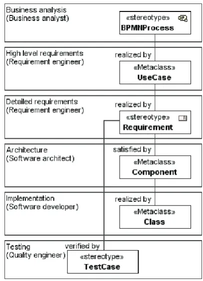
In this section we will present an example of a software project, whose traceability will be analyzed. Let us make an assumption that the project is developed according to a methodology, which consists of the following stages: business analysis, requirements (high level and concrete), architectural design, implementation, and testing.
In our sample we are developing Training Organization System by going from business analysis to implementation through different development stages (Figure 1). Each development stage is covered by successive one: business processes are described with use cases in high level requirements; on their basis, detailed requirements are created and verified with test cases and satisfied with architectural components; components are implemented with code classes. Traceability relations would be created between artifacts from different stages in such a way that finally we would have fully traceable specification of the Training Organization System project. The development methodology is based on combination of several OMG Meta Object Facility (MOF) [31] based modeling languages, which are the most suitable for every stage: business analysis uses BPMN; requirement specification applies UML and SysML requirements; architectural design, implementation and testing is based on UML. The most suitable relations from modeling languages are used for modeling traceability between stages: “satisfy” and “verify” relations are dedicated for SysML requirements coverage, “abstraction” dependency is the UML relation for connecting different abstraction levels.
For specifying each stage, a particular role is responsible, e.g. requirement engineer is responsible for high and detailed requirements etc. Each role checks not only artifacts for which he or she is responsible but also related ones (e.g. requirement engineer should check business processes, which
should be covered by requirements). The desirable traceability means should help for doing this by visualizing relations between artifacts from different stages, allowing navigating through them, and automatically analyzing e.g. coverage of particular artifacts.
)LJXUHThe structure of the Training Organization System
project
)LJXUHTraining Organization System model (fragment)
Specification of the use case “Inform existing customers about trainings” is given in Table 2.
Use case details are described in concrete requirements for notification system: 1) functional requirements “Edit notification”, “Edit participant list”, “Send notification”; 2) requirements inspired by business rules: “Notification method”, “Notification subscription”; 3) data requirements “Notification types” (“Notification types” cover requirements for notifications from other use cases as well). Requirements are satisfied in the architectural design by the “Notification” component, and verified by test cases (e.g. “Subscription for notification” and “Notification for feedback”).
A model is complete, if: 1) design and test planning stages are finished; 2) all business processes to be implemented are covered with use cases; 3) use cases are covered with concrete requirements; 4) all leaf requirements are satisfied by components from the stage of architectural design and verified by test cases.
The case study described in section 6 shows in details how the completeness of a design could be
ensured by creating and analyzing traceability information. A case of applying derived properties for BPMN [30] traceability is presented in [36]. Next section presents the proposed Derived Property Metamodel for ensuring traceability and avoiding typical traceability issues, described in Table 1.
7DEOHUse case specification example (shortened) Use case:Inform existing customers about trainings Pre-condition: Customer is subscribed to open enrolment training
Business rules:
It is obligatory that customer is subscribed to get notifications if customer is subscribed to open enrolment training.
It is obligatory that notification is sent to e-mail provided in customer’s profile.
Actor:Manager
Triggering event: Open enrolment training is confirmed or canceled
Related use cases: include: Send notification
User actions System reaction
1. Choose training 1.1. Show information about training
1.2. Edit a notification text 2. Choose preview of participants
2.1. Show list of participants, who should get the notification 2.2. Edit list of participants
3. Send the notification 3.1. Perform use case “Send notification”
3.2. Show sent notification confirmation
Post-condition:Notifications are sent to customers about confirmed or canceled training
'HULYHGSURSHUW\PHWDPRGHO
In order to be able to define derived properties in the modeling environment, we need to extend a modeling language for specifying derived property details. UML [35] and other modeling languages provided by Object Management Group (OMG) have the standard extension mechanism – profiling.
UML extension for derived properties reuses UML properties and introduces two stereotypes for specifying derived properties as presented in Figure 3.
'HULYHG SURSHUW\ VSHFLILFDWLRQ. The stereotype <<derivedPropertySpecification>> extends UML Property for specifying derived property, which has
expression, stereotyped as <<expressionSpecification>>, for defining how this
)LJXUHUML metamodel extended with derivedPropertySpecification stereotype for specifying derived properties
([SUHVVLRQ VSHFLILFDWLRQIRUGHULYHGSURSHUWLHV. The heart of the derived property is the expression according to which it is calculated. The stereotype <<expressionSpecification>> extends UML metaclass “OpaqueExpression” having properties “language” and “body”, which are used to specify expression in needed language. The stereotype <<expressionSpecification>> redefines the property “body” of the metaclass “OpaqueExpression” by our introduced expression type – a primitive “ExpressionBody”. In order to meet criteria established for traceability schema (Table 1), we have introduced several different types of such expressions: SimpleExpression, multilevel MetachainExpression, OCLExpression, and BinaryOrScriptingExpression. Such expressions may be supported by various UML CASE tools. Other expression types may be introduced as needed.
6LPSOH H[SUHVVLRQ W\SH It allows expressing direct dependencies through UML relationships, properties and tags, with later filtering according to directions and properties of relations. An example of calculating a derived property “Verifies” from the simple expression type (“Verify” abstraction) is presented in Figure 4.
)LJXUHA derived property “Verifies” is calculated on the
base of abstraction “verify”
Simple expressions for derived properties may be defined in specifications of UML model elements.
)LJXUHA derived property “Realized in Architecture”
A metachain expression links pairs of metaclasses/stereotypes and properties/tags. For creating the derived property “Realized in Architecture” a metachain expression must search for components indirectly related to BPMN business process via use cases and requirements. An example of MetaChain Expression editor is depicted in Figure 6. It allows defining property chains for navigating from source elements to target elements.
)LJXUHA metachain expression for search of indirectly
related components
The aforementioned metachain expression contains specification of 3 links:
RealizedInArchitecture;MetaChain;
/Customization::BPMNprocess.realizedBy. UseCase.realizedBy.SysML::
Requirement.SatisfiedBy;
The grammar of metachain expressions mapping object links to property values is presented in BNF (Backus–Naur Form):
<Metachain expression>::=<expression name>";MetaChain;"
<full classified name of the metaclass or stereotype to be extended with derived property>";"<Property chain part>";" <Property chain part>::=<Step>|<Step>"."
<Property chain part>
<Step>::=<Metaclass>"."<Property>| <stereotype>"."<tag>
The advantage of MetaChain Expression editor is that it does not require knowing any programming language (e.g. OCL) to create derived properties with complex logic.
2EMHFW &RQVWUDLQW /DQJXDJH 2&/ H[SUHVVLRQ W\SH For specifying indirect dependencies, standard OCL expressions can be used. E.g. the derived property „Realized in Architecture” (Figure 6) is specified by the OCL expression:
context BPMNProcess::
RealizedInArchitecture:Component derive:self.supplierDependencyo select(a|a.oclIsKindOf(Abstraction)). clientoexists(b|b.oclIsKindOf(UseCase)). supplierDependencyo
select(c|c.oclIsKindOf(Abstraction)). clientoexists(d|d.oclIsKindOf
(SysML::Requirement)).supplierDependency oselect(e|e.oclIsKindOf
(SysML::Satisfy)).cliento
exists(f|f.oclIsKindOf(Component))
%LQDU\ RU 6FULSWLQJ ([SUHVVLRQ 7\SH. Any scripting language (BeanShell, JRuby, Jython, Groovy, JavaScript) or programming language as Java supported by the CASE tool can be used for calculating a derived property on the base of similarity between names, types of elements or relations, or a number of levels between source and target. Property derivation rules can be any combinations as unions of the expression types introduced.
7UDFHDELOLW\IUDPHZRUN
The section presents the Derived Property Based Traceability Framework, intended for calculating derived properties on the fly: analyzing specifications of derived properties, calculating them from existing model elements, and dynamically updating them according to changes in models (Figure 7).
)LJXUHDerived Property Based Traceability Framework
0RGHOGULYHQ '6/. Domain-Specific Languages are used in many CASE tools. The purpose of DSL is to increase abstraction in software development, making it faster and easier [49]. If the general-purpose language lacks expressiveness that is clear to implementers but is not a part of the UML standard, domain-specific modeling can help. For a traceability framework, CASE tool developers can use their own DSL engines or create new ones. The size of efforts for creating or adapting a DSL depends on the advantages of a tool.
7UDFHDELOLW\ VFKHPDVSo we can define derived properties, but we need a “glue” to have them working for the traceability purpose. Traceability schemas (sets of traceability relations) are dependent on traceability context – e.g. modeling language such as BPMN or software engineering process as described in our case study, or the purpose of traceability. It is desirable to implement them as separate modules that could be loaded and reused in various projects. Derived properties defined in the loaded module are added to elements of considered models.
0RGHOLQJ WRRO VSHFLILF YLVXDOL]DWLRQ DQDO\VLV DQG QDYLJDWLRQ FDSDELOLWLHV. Derived properties appear in specifications of corresponding elements and other places in the same way as regular UML properties. It is possible to visualize and analyze traceability information, to perform impact analysis, and validate model consistency adapting CASE tool specific visualization, navigation and analysis means. This is the only framework part dependent on a particular UML CASE tool.
7UDFHDELOLW\IUDPHZRUNLPSOHPHQWDWLRQLQ
0DJLF'UDZ
The framework was implemented in UML CASE tool MagicDraw in accordance with the overall conception of MagicDraw development, i.e. reusing UML extensions and facilities already implemented in the tool.
One of such extensions is MagicDraw DSL Engine [29, 47, 51] a customization engine for model driven tool environment, which allows initializing specific models; adding semantic rules; creating custom specification dialogs, smart manipulators and derived properties.
The MagicDraw DSL Engine is used by adding a property stereotyped with <<derivedPropertySpecification>> stereotype into MagicDraw DSL Customization class (i.e. class stereotyped as <<Customization>>) (Figure 8). The definition of the tag „customizationTarget“ (Figure 9) of this class specifies in which element type (UML or extended one) the derived property will be created.
)LJXUHSpecification of derived properties of a
customization class in MagicDraw CASE tool
The DSL engine also is used for creating traceability specific derived properties and traceability schemas. In MagicDraw, a traceability schema is obtained by grouping customizations of derived properties into semantic groups (e.g. “Specification”, “Realization”, and “Other”) (Figure 9), which are visible in specifications of model elements, and other places. Various traceability schemas are held in separate modules and can be loaded in a project depending on a modeling language, development process or domain in use.
An example of a traceability schema which can be used as a module in MagicDraw project is presented in Figure 9.
)LJXUHThe traceability schema “Traceability
customization” as a module
7&DVHVWXG\
In this section we shortly present exploratory case study research done according to methodology described in [43]. This case study helps to show the suitability of the proposed traceability approach. The sample under analysis is described in section 3.
3UREOHP VWDWHPHQW We need to ensure the consistency of the investigated project after making changes to its artifacts and avoid typical traceability issues, described in Table 1.
5HVHDUFK REMHFWLYHis to investigate how Derived Property Based Traceability Approach improves traceability in software development process using a particular development methodology and how it helps for different roles (i.e. business analyst, requirement engineer, software architect, and quality engineer) in different development stages.
Research questions that should be answered:
1. Can we ensure that a project of our system is consistent?
2. Can we know which parts of the system will be impacted by changes in order to evaluate risks and costs of changes, and update related parts for keeping requirements consistent? 3. Can we know what would influence our
implementation if we change project parts (e.g. business processes) having no direct relations with implementation (e.g. components), and vice versa?
4. Can we avoid typical traceability issues, described in Table 1?
&DVH DQG VXEMHFW VHOHFWLRQ For the research, we selected a development project of a medium size application, from business analysis till deployment stages, by using popular modeling languages such as BPMN, SysML [34], and UML.
'DWD FROOHFWLRQ SURFHGXUHV Qualitative data about results of experiment will be collected by applying derived properties in modeling tool for analyzing system specification.
$QDO\VLV SURFHGXUHV We will analyze a traceability schema satisfying our project structure, defined in Fig. 1, by the following steps:
6WHS. Specifying traceability rules – derived properties for each cross development stage relation including transitive dependencies from business process to components, and vice versa;
6WHS. Grouping derived properties into
WUDFHDELOLW\ JURXSV í IRU NQRZLQJ ZKHUH WR ORRN IRU
traceability information;
6WHS. Applying traceability properties for analyzing system;
6WHS. Visualizing traceability information – derived properties, and using them for change impact and coverage analysis;
6WHS. Analyzing results and checking answers to research questions.
&DVHDQGVXEMHFWGHVFULSWLRQThe SysML, which was selected as a requirement specification language, has dedicated elements for requirement definition and relations between different stages of development. This allows having a clear schema of traceability. For other development stages, BPMN and UML languages were selected (Section 3).
6SHFLI\LQJ WUDFHDELOLW\ UXOHV Traceability rules between structural parts of the project (Figure 2) are presented in Table 3. Usually, traceability rules are created for each relation between main artifacts between which traceability is decided to be created and tracked. In order to achieve two–way traceability, derived properties for traceability rules are created for each last element of traceability relations. If traceability relation is established between artifacts from different stages and we are going from business process to implementation, we can treat traceability rules as realization ones; if we are going from implementation to business process, we can consider them as specification rules, and accordingly group them into realization and specification groups.
7DEOHTraceability rules for Training Organization System project
# Rule name Source element Expression Target element Description
Forward traceability – realization
1 Realized By Business process Abstraction Use case High level requirement realizing business process
2 Realized By Use case Abstraction Requirement Concrete requirement realizing high level requirement
3 Satisfied By Requirement Satisfy Component Architecture component satisfying requirement
4 Realized In
Architecture Business process Transitive relation: Business process> Abstraction>Use case> Abstraction>
Requirements>Satisfy> Component
Component Architecture component realizing business process
Other
In Table 3, the column “Rule name” represents a name of each derived property; “Source element” – its owner; “Expression” defines how the derived property is calculated; “Target element” corresponds to a value of the derived property. For derived properties 1–3, 5, 6 we use simple expression types, because their rules are based on direct relationships in the model. For derived property 4, we apply a metachain expression because we have a transitive relation “Business process > Abstraction > Use case > Abstraction > Requirements > Satisfy > Component”.
*URXSLQJ 7UDFHDELOLW\ 5XOHVDerived properties are grouped and visualized in MagicDraw user interface with a help of MagicDraw DSL engine. We can analyze derived property groups in element’s specification win3dow, property panel, element’s
context menu, note on a diagram, and Relation Map diagram.
9LVXDOL]DWLRQ DQG $QDO\VLV RI 7UDFHDELOLW\ 5XOHV Once derived properties are specified, they appear in specifications of corresponding elements and other places in the same way as regular UML properties. Now, by visualizing and analyzing traceability information, we can discover related elements, which will be impacted by changes (i.e. we can perform impact analysis). Also, we can validate model consistency by performing coverage analysis for discovering whether all requirements are satisfied by design and verified with test cases, or not. Transitive traceability is visualized by Relation Map (Figure 10).
)LJXUHRelation Map – graph based visualization enabling analysis of multilevel relations, e.g. from business
analysis stage (1) to high level requirements (2), concrete requirements (3), and architecture (4)
Single level traceability (through direct relations) can be visualized by various modeling tool means, e.g. traceability matrix (Figure 11). A traceability matrix allows performing a coverage analysis between artifacts of a project. The coverage analysis, supported by forward and backward traceability properties, gives coverage information between immediate higher and lower stages.
Another coverage analysis means is a generic table, whose empty cells in the rows with leaf requirements indicate lack of consistency in a project. Additionally, a coverage analysis report, which is generated by documentation generation capability, computes project completeness in percent.
Finally, it is possible to check completeness of traceability and validate non–existence of cyclic relationships by using MagicDraw validation feature that can show invalid elements in Relation Map (Figure 12), validation result dialog, containment tree, diagrams, etc.
Furthermore, it is not necessary to create any diagram or other artifacts visualizing traceability relations in order to discover uncovered artifacts. They will automatically be highlighted in all available views and containment tree.
9DOLGDWLRQ UXOHV LQ 2&/are another means for checking traceability relations and getting information about uncovered parts of the project (Table 4). It is
worth to note that OCL (as well as Binary or Scripting Expressions) allow specifying more powerful traceability and validation rules than other traceability expression types.
)LJXUHMatrix representing traceability relations among
)LJXUHValidation results below Relation Map inform about uncovered project parts,
e.g. business process and high level re-quirements
7DEOHValidation rules in OCL to check completeness of traceability (coverage of artifacts)
# Rule name Rule header OCL Expression
Forward traceability – realization
1 Realized By Context BPMNProcess::realizedBy: UseCase
derive:self.realizedByosize()>0
2 Realized By Context UseCase::realizedBy: Requirement
derive:self.realizedByosize()>0
3 Satisfied By Context Requirement::realizedBy: Component
derive:self.satisfiedByosize()>0
4 Realized in Architecture
Context BPMNProcess::realizedBy: Component
derive:self.realizedInArchitecture osize()>0
Other
5 Verified By Context Requirement::realizedBy: TestCase
derive:self.verifiedByosize()>0
6 Verifies Context TestCase::realizedBy: Requirement
derive:self.verifiesosize()>0
… ... ... ...
&RQVHTXHQFHV IURP WKH FDVH VWXG\ The case study of Training Organization System project, developed with applying the Derived Property Based Traceability Approach implemented in the CASE tool MagicDraw, has provided the following answers to research questions:
1. We can ensure that a project of our system is consistent by validating traceability information about coverage of artifacts in each stage of the development process using MagicDraw validation means;
2. We can know which parts of the system will be impacted by changes, by analyzing traceability links using Relation Map, Traceability matrix, Generic table, or Coverage Analysis Report;
3. We can know what parts of our project would be affected if we change artifacts (e.g. business processes) having no direct relations with implementation (e.g. components), and vice versa, by defining and using MetaChain Expressions;
4. We can avoid typical traceability issues, described in Table 1, as:
x Traceability schema and rules are
customizable and model driven via means of profiling and model-driven DSL engine, including custom derived properties;
same manner as regular properties, and can be visualized and analyzed using standard means of the CASE tool;
x Model is not polluted by traceability information as specification of traceability rules using derived properties does not affect model. Derived properties are calculated on the base of existing model properties and appear only in specifications and traceability analysis means;
x Models of different stages of the project avoid tight coupling because derived properties are calculated from existing relations and do not require additional ones. For example, a derived property is devoted for showing what components satisfy detailed requirements, but there is no need to introduce for this new relations – existing relations from components to requirements are reused.
x Creation and maintenance of traceability relations is automatic and flexible as required derived properties can be added by users themselves and automatically calculated by the tool on the base of model information.
8&RQFOXVLRQVDQGIXWXUHZRUNV
1.Analysis of current approaches to traceability in software and system projects has shown that the major drawbacks of current traceability implementations are: 1) inflexibility, as traceability rules are fixed (not customizable, or customization is not model-driven); 2) pollution of models with additional model level relations for defining traceability information; 3) tight coupling between models of different stages of a project (e.g. requirements and design) arising due to additional relations for traceability support; 4) little or no reuse of capabilities of existing CASE tools; and, especially, 5) manual creation and maintenance of traceability relations what usually causes undesirable overhead.
2.We proposed to solve these problems by Derived Property Based Traceability Approach via extending UML metamodel for specifying derived properties. Derived property expressions may be simple, using properties of UML metamodel, or more complex, specifying metaproperty chains, expressions in OCL or other languages, and combinations of the previous.
3.The implementation of Derived Property Based Traceability Approach in CASE tool MagicDraw was made with reusing previous tool extensions as MagicDraw DSL and Customization profiles as well as other existing means (dependency matrices, report templates, and validation rules).
4.The proposed traceability framework improves existing traceability approaches with decrease of overhead as derived properties are calculated by a modeling tool and dynamically updated according to changes in models. Derived properties are defined using OCL expressions and other tool– specific means, and access visualized traceability information in an ordinary way.
5.The case study of the Training Organization System project, covering typical traceability problems, has shown that developers using Derived Property Based Traceability approach are capable to define required traceability relations including transitive ones; analyze traceability information using common and specialized visualization means of the considered CASE tool; validate completeness of covering requirements by realizing elements, and know project parts, which should be updated due to requirement changes. 6.Derived Property Based Traceability Approach
already has been successfully adopted by companies (including large aerospace and telecommunication corporations) and academic institutions (e.g. Kaunas University of Technology, which has introduced the approach into Information Systems Development curriculum). Created derived property expression specification engine became universal querying engine in MagicDraw tool; it was reused in Relation Map, Dependency Matrix, and many other places.
7.Derived Property Based Traceability Approach
may be implemented in any model-driven UML CASE tool though implementation efforts depend on existing tool capabilities: DSL and OCL support, visualization and analysis means etc. In this respect advantages of MagicDraw tool revealed a favorable environment for implementing the traceability framework. Other CASE tools might have less suitable means for this purpose. This will make implementation of the approach less flexible, but will not forbid implementing it and benefiting from traceability solution.
$FNQRZOHGJHPHQW
The authors would like to thank No Magic, Inc, especially the MagicDraw product team for comprehensive support.
The work described in this paper has been carried out within the framework of the Operational Program for the Development of Human Resources 2007-2013 of Lithuania „Strengthening of Capacities of Re-searchers and Scientists" project VP1-3.1-ŠMM-10-V-02-008 „Integration of Business Processes and Business Rules on the Base of Business Semantics" (2013-2015), funded by the European Social Fund (ESF).
5HIHUHQFHV
[1] /$EORQVNLV /1HPXUDLWơ. Discovery of complex model implementation patterns in source code. In: Information technology and control, 2010, Vol. 39, No. 4, pp. 291-300.
[2] 1$L]HQEXG5HVKHI %71RODQ -5XELQ <6KDKDP*DIQL Model traceability. In: IBM Systems JournalModel-driven software development, 2006, Vol. 45, No.3, pp.í
[3] .$QDVWDVDNLV %%RUGEDU **HRUJ ,5D\ On Challenges of Model Transformation from UML to Alloy. Software and Systems Modeling, 9(1), Springer Berlin / Heidelberg, 2010, pp.í
[4] .0 $QGHUVRQ 51 7D\ORU (--U:KLWHKHDG
Chimera: hypermedia for heterogeneous software development enviroments. In: ACM Trans. Inf. Syst., 2000, Vol. 18, No. 3, pp.í
[5] $16,,(((. IEEE Guide to Software Requirements Specification, ANSI/IEEE Std 830–1984. IEEE Press, Piscataway, 1984.
[6] *$QWRQLRO *&DQIRUD *&DVD]]D $'H/XFLD (0HUOR Recovering traceability links between code and documentation. In: IEEE Transactions on Software Engineering, 2002, Vol. 28, No. 10, pp.í [7] 6%LIIO $$XUXP %%RHKP +(UGRJPXV
3*UQEDFKHU Value-based software engineering. Springer-Verlag New York, Inc. Secaucus, NJ, USA, 2005.
[8] 6$%RKQHU 56$UQROG Software Change Impact Analysis. IEEE Computer Society Press, Los Alamitos, California, USA, 1996.
[9] /&%ULDQG </DELFKH 7<XH Automated traceability analysis for UML model refinements. In: Information and Software Technology, 2009, Vol. 51, No. 2, pp. 512527.
[10]%5%U\DQW -*UD\ 00HUQLN 3-&ODUNH 5%)UDQFH*.DUVDL. Challenges and Directions in Formalizing the Semantics of Modeling Languages. Computer Science and Information Systems, 2011, Vol. 8, No. 2, pp. 225–253.
[11]-&RRNH 56WRQH A Formal Development Framework and Its Use to Manage Software Production. IEE Colloquium on Tools and Techniques for Maintaining Traceability During Design, 1991, pp. 10/1.
[12],&UQNRYLü 8$VNOXQG $3HUVVRQ'DKOTYLVW
Implementing and Integrating Product Data
Management and Software Configuration Management. Artech House, London, 2003.
[13]-'LFN. Rich Traceability. In: Proceedings of the 1st International Workshop on Traceability in Emerging Forms of Software Engineering, Edinburgh, Scotland, 2002.
[14]-5(UHQNUDQW] Release Management within Open Source Projects. In: Proceedings of the 3rd Open Source Software DevelopmentWorkshop, Portland, Oregon, USA, May, 2003, pp. 51–55.
[15]5)UDQFH %5XPSH Model-driven development of complex software: a research roadmap. In:FOSE ’07: Future of Software Engineering Proceedings, IEEE Computer Society, New York, 2007, pp.í
[16]*HHQVRIW. Reqtify, 2011. [Accessed 10
February 2012] Available at:
http://www.geensoft.com/en/article/reqtify.
[17]-$*RJXHQ Formality and informality in requirements engineering. In: 2nd International Requirements Engineering Conference (ICRE’96) Proceedings, IEEE Computer Society, New York, 1996.
[18]2&=*RWHO$&:)LQNHOVWHLQAn artifact is of the Requirements Traceability Problem. In: Proceedings of the First International Conference on Requirements Engineering, Utrecht, The Netherlands, 1994, pp. 94–101.
[19]-++D\HV $'HNKW\DU -2VERUQH Improving requirements tracing via information retrieval. In: 11th IEEE International Requirements Engineering Conference (RE'03) Proceedings, IEEE Computer Society, New York, 2003, pp.í
[20],%0. DOORS family, 2012. [Accessed 10
August 2012]. Available at: http://www-01.ibm.com/software/awdtools/doors/product line/ [21],%0. IBM Rational Software Architect, 2011.
[Accessed 10 February 2012] Available at: http://www-01.ibm.com/software/rational/products/ swarchitect.
[22],%0. Rational RequisitePro, 2011. [Accessed 10 February 2012] Available at: http://www-306.ibm.com/software/awdtools/reqpro.
[23],-DFREVRQ *%RRFK -5XPEDXJK The Unified Software Development Process. Addison-Wesley Professional, Boston, MA, 1999.
[24]3/HWHOLHU A Framework for Requirements Traceability in UML-Based Projects. In: Proceedings of the 1st International Workshop on Traceability in Emerging Forms of Software Engineering, Edinburgh, 6FRWODQGí
[25]$/RSDWD 0$PEUD]LnjQDV 6*XGDV 5%XWOHULV
The main principles of knowledge-based information systems engineering. In: Elektronika ir elektrotechnika, 2012, Vol. 4, No. 120, pp. 99–102. [26]7'0HLMOHU -31\WXQ $3ULQ] +:RUWPDQQ
Supporting fine-grained generative model-driven evolution. In: Software and Systems Modeling, 2010, Vol. 9, No. 3, pp.í
[27]70HQV 39DQ *RUS A taxonomy of model transformation. In: Electronic Notes in Theoretical
Computer Science (ENTCS), 2005, Vol. 152,
pp. 125-142.
Information Technology and Control, 2011, Vol. 40, No. 3, pp. 181-190.
[29]1R 0DJLF ,QF. UML Profiling and DSL, 2011. [Accessed 12 February 2012] Available at: https://secure.nomagic.com/files/manuals/UML% 20Profiling%20and%20DSL%20UserGuide.pdf.. [30]20*. Business Process Model and Notation (BPMN),
Version 2.0. OMG Document Number: formal/2011-01-03, 2010.
[31]20*. Meta Object Facility (MOF) Core
Specification, Version 2.0. OMG Document Number: formal/06-01-01, 2006.
[32]20*. Meta Object Facility (MOF) 2.0 Query/View/Transformation Specification, Version 1.0. OMG Document Number: formal/2008-04-03, 2008.
[33]20*. Object Constraint Language, Version 2.2. OMG Document Number: formal/2010-02-01, 2010. [34]20* OMG Systems Modeling Language (OMG
SysML), Version 1.2. OMG Document Number: formal/2010-06-01, 2010.
[35]20* OMG Unified Modeling Language (OMG
UML), Version 2.3. OMG Document Number:
formal/2010-05-05, 2010.
[36]63DYDONLV /1HPXUDLWơ (0LOHYLþLHQơ Towards Traceability Metamodel for Business Process Modeling Notation. In: Building the e-World Ecosystem, I3E 2011, IFIP AICT 353, 2011, 177–188. [37])$&3LQKHLUR -$*RJXHQ. An Object-Oriented
Tool for Tracing Requirements. In: IEEE Software, 1996, Vol. 13, No. 2, pp.í
[38],3RUUHV Rule-based update transformations and their application to model refactorings. In: Software and Systems Modeling, 2005, Vol. 4, No. 4, pp.í [39]%5DPHVK 0(GZDUGVIssues in the development
of a requirements traceability model. In: Proceedings of the IEEE International Symposium on Requirements Engineering, IEEE Computer Society, New York, 1993, pp. 256–259.
[40]%5DPHVK 0-DUNH. Toward reference models for requirements traceability. In: IEEE Transactions on Software Engineering, 2001, Vol. 27, No. 1,
pp.í
[41]%5DPHVK 73RZHUV &6WXEEV 0(GZDUGV
Implementing requirements traceability: a case study.
In: 2nd IEEE International Symposium on
Requirements Engineering (RE’95) Proceedings, IEEE Computer Society, New York, 1995, pp. 89–95. [42]-5HFNHU “Modeling with tools is easier, believe
me’’í 7KH HIIHcts of tool functionality on modeling grammar usage beliefs. In: Information Systems, 2012, Vol. 37, pp. 213–226.
[43]35XQHVRQ 0+RVW Guidelines for conducting and reporting case study research in software engineering. In: Empirical Software Engineering, 2009, Vol. 14, No. 2, pp. 131–164.
[44]&6FKPLGW. Model-Driven Engineering. In: IEEE Computer, 2006, Vol. 39, No. 2, pp. 25–31.
[45].6FKZDEHU The Enterprise and Scrum. Microsoft Press, Redmond, WA, USA, 2007.
[46]6$6KHUED .0$QGHUVRQ 0)DLVDO A Framework for Mapping Traceability Relationships. In: Proceedings of the 2nd International Workshop on Traceability in Emerging Forms of Software Engineering at 18th IEEE International Conference on Automated Software Engineering, Montreal, Canada, 2003, pp. 3239.
[47]'âLOLQJDV 59LWLXWLQDV $$UPRQDV /1HPXUDLWơ Domain-specific modeling environment based on UML profiles. In: Information Technologies' 2009: proceedings of the 15th International Conference on Information and Software Technologies, IT 2009, Kaunas, Lithuania, April 23-24, Kaunas University of Technology, Technologija, Kaunas, 2009, pp.í
[48]6SDU[6\VWHPV.Enterprise Architect, 2011. [Accessed 10 February 2012] Available at: http://www.sparxsystems.com/.
[49]-6SULQNOH00HUQLN-37ROYDQHQ'6SLQHOOLV
Guest Editors' Introduction: What Kinds of Nails Need a Domain-Specific Hammer? In: IEEE Software, 2009, Vol. 26, No. 4, pp. 15–18.
[50]5(.6WLUHZDOW 0'HQJ %+&&KHQJ UML formalization is a traceability problem. In: TEFSE ’05: Proceedings of the 3rd International Workshop on Traceability in Emerging Forms of Software Engineering, ACM, New York, 2005, pp. 31–36. [51]'âLOLQJDV 5%XWOHULV Towards Implementing a
Framework for Modeling Software Requirements in MagicDraw UML. In: Information Technology and Control, 2009, Vol. 38, No. 2, pp. 153–164.
[52](7U\JJHVHWK21\WU¡Dynamic Traceability Links Supported by a System Architecture Description. In: Proceedings of the IEEE International Conference on Software Maintenance, Bari, Italy, 1997, pp.í [53]39DQ*RUS '-DQVVHQV 7*DUGQHUWrite once,
deploy N: a performance oriented MDA case study. In: Proceedings of the IEEE International Conference on Enterprise Distributed Object Computing, 2004,
pp.í
[54]9LVXDO SDUDGLJP. Visual Paradigm for UML, 2011. [Accessed February 2012] Available at: http://www.visual-paradigm.com.
[55]0:HVW. Quality Function Deployment in Software Development. In: IEE Colloquium on Tools and Techniques for Maintaining Traceability During
Designí
[56]6:LQNOHU -3LOJULP A survey of traceability in requirements engineering and model-driven development. In: Software and Systems Modeling, 2010, Vol. 9, No. 4, pp.í.