INTRODUCTION
Pumping units of drilling rigs work under high dynamic loadings. Rational design and ex-ploiting parameters of these machines can be de-fined only on the basis of a comprehensive study of oscillation processes as well as an investiga -tion of a stress-strain state of their parts. The com-plexity of pumping units as technical systems, a repeating character of functioning, and clearly expressed interdependence of phenomena of dif-ferent physical nature require developing special methods of dynamic calculations. In view of the necessity to simultaneously ensure high produc-tivity of circulatory systems of drilling rigs, as well as durability and reliability of structure el-ements, particular significance was rendered to
improve the analysis methodology of non-steady operational modes of pumping units.
Productivity and reliability of a drilling rig considerably depend on an efficient operation of a pumping unit which provides moving debris to the surface by means of drilling fluid injec -tion into a well. The investiga-tion of dynamics of pumping units is directly connected with the defi -nition of their summary inertia moments as func-tions of rotational angles of root shafts and it was reviewed by Yutaev [11]. The basics of dynam-ics of mechanisms and machines were presented by Dresig et al. [3, 9, 1]. In the papers written by Erkaya et al. [4] and Mudrik [8], the theoreti-cal bases of mathematic modeling of mechanitheoreti-cal systems dynamics with variable inertia charac -teristics of links and investigation examples of
Drive System Parameters Influence on Run-Up Process of the Drilling
Rig Pumping Unit
Roman Kovalchuk
1, Yuriy Molkov
2, Taras Lenkovskiy
2, Oleksandr Grytsenko
3,
Volodymyr Krasinskyi
3, Tomasz Garbacz
4*1 Hetman Petro Sahaidachnyi National Army Academy, Department of Engineering Mechanics, 32 Heroes of
Maidan St., Lviv 79012, Ukraine
2 Karpenko Physico-Mechanical Institute of the NAS of Ukraine, Department of Strength and Durability of
Structures under Complex Loading, 5 Naukova St., Lviv 79060, Ukraine
3 Lviv Polytechnic National University, Department of Chemical Technology and Plastics Processing,
Bandera 12 St., 79013 Lviv, Ukraine
4 Lublin University of Technology, Faculty of Mechanical Engineering, Department of Polymer Processing,
ul. Nadbystrzycka 36, 20-618 Lublin, Poland
* Corresponding author’s e-mail: [email protected]
ABSTRACT
A mathematical model of dynamic processes in pumping unit of a drilling rig with friction clutch, taking into ac-count variable moment of inertia of slider-crank mechanism links and random number of pistons of the pump, was developed. Joint integration of differential equations of motion of pumping unit parts was carried out with numeri-cal methods. The numeri-calculations performed considered the torque moment of friction in the clutch and equations of electromagnetic processes in asynchronous motor. The results of research of run-up processes of pumping unit were presented. The influence of parameters of friction clutch on the performance of pumping unit was established.
Keywords: dynamics of machines, non-stable modes of operation, run-up process, friction clutch, pumping unit, dynamic load
Volume 12, Issue 4, December 2018, pages 199–206
https://doi.org/10.12913/22998624/100442
Research Journal
Accepted: 2018.11.05such systems were presented. Theoretical and practical issues of kinematics and dynamics of crank-and-slider mechanisms as well as reducing of masses of mechanisms and structure elements were considered in the investigations by Fung et al. [5, 10, 12, 7]. According to Kharchenko’s [6] approach, a calculation process based on compat-ible integration of differential equations of move -ment, written taking into account the instability of a summary inertia moment of crank-and-slider pumping mechanisms, and equations of electro-magnetic processes in an asynchronous motor was proposed. The vibration phenomena of drill string were investigated by Christoforou[2].
Nevertheless, the influence of friction clutch on the dynamic loading of the elements of pump-ing unit has not been investigated enough. Hence, there is a need for carrying out a detailed analysis of the dynamic phenomena in pumping unit and its drive with the purpose of rational selection of operational parameters of the friction clutches, which would provide the improvement of circula -tion system components strength and reliability. In this study, a mathematical model of dynamic processes in a pumping unit with variable num -ber of pistons and the friction clutch, consider-ing inconstancy of inertia moments of the slider-crank mechanism of the pump and connection of mechanical and electromagnetic oscillatory processes was developed. The joint integration of the differential equations of movement of the mechanical system of variable structure as well as the equations of the electromagnetic phenomena in the asynchronous motor gives an opportunity to analyze the processes taking place at the run-up and at the stable mode of drilling pumps operation.
DIFFERENTIAL EQUATIONS OF THE
PUMPING UNIT MOVEMENT
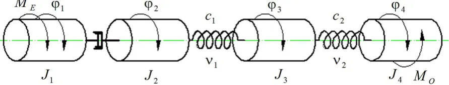
The mechanical system of the pumping unit, which consists of an asynchronous motor, an air
clutch, a belt gear, a reducer and piston pump is illustrated schematically in Fig. 1, where: J1 – a reduced moment of inertia of motor’s rotor with the driving part of the air clutch; J2 – a reduced moment of inertia of the air clutch driven part with a shaft and driving pulley of the belt gear;
J3 – a reduced moment of inertia of transmission shaft with a gear-wheel and a driven pulley of the belt gear; J4 – a reduced moment of inertia of the slider-crank mechanism of the pump; с1 – reduced rigidity of the cone belts; ν1 – reduced coefficient of the belts damping; с2 – reduced rigidity of the gear reduction unit; ν2 – reduced coefficient of the gear drive damping; МЕ – reduced electromag-netic moment of a motor; Мd – movement drag moment, which has an effect on the driving shaft of a pump; φ1, φ2, φ3, φ4 – reduced angular coordi-nates. Inertial and elastic-dissipative parameters of the mechanical system are reduced to driving shaft of a pump.
Equations of the unit elements movement are composed similarly to the Lagrange’s equations of the second kind
j j j j j
Q q q q
T q
T dt
d
j1 ,4
, (1)where: Т and Π are the kinetic and potential ener-gies of the mechanical system;
Φ – the Rayleigh dissipation function; Qj – generalized force;
qj– generalized coordinate;
t – time.
Designating as the generalized coordinates the following values
2 2 1
1; q
q ; q33; q4 4, (2)
the kinetic energy of the system is presented as
2 2
2 2
2 4 4 2 3 3 2 2 2 2 1
1
J J J J
T , (3)
where: ω1, ω2, ω3, ω4 – an angular velocity of the
pulley of the belt gear, an angular veloc -ity of the high-speed shaft of the reducer, joined with driven pulley of the belt gear and a real angular velocity of the root shaft of the pump, respectively, reduced to the root shaft,
2 2
1
1 ,
dt d dt d , 4 4 3
3 ,
dt d dt
d . (4)
The potential energy and the Rayleigh dissi-pation function with consideration of the depen-dencies (2), (4) are written as
2 2 2 4 3 2 2 3 21
c c ;
2 2 2 4 3 2 2 3 21
.
(5)
For the mode with sliding in the air clutch, taking derivations of formulae (3) and (5) and in -serting them in the Lagrange’s equations of the second kind (1), we receive the equations of mo -tion written as follows:
f
Eз M
M dt d
J 1
1 ;
2 3 1 2 3
1
2
2ddt M c
J f ;
2 3 1 2 3 2 3 4 2 3 4 1
3
3
c c
dt d
J ;
Md
c J dt d
J
4 3 2 4 3 2 2 4 4 4 4
4 21 ,
(6)
where: Mf– a moment of friction in the air clutch,
reduced to the root shaft, which is changed according to the law:
t
Mf t , if ttr;
r t
f t
M , if ttr,
where: tr –clutch filling time;
αt –coefficient, which is determined by the dependence
r f t Mt 0
,
where: Мf0 – maximum moment of friction in a clutch.
The reduced moment of the motor is found according to the formula
u M
ME E0 , (7)
where: МЕ0 –real electromagnetic moment of the motor; u –gear-ratio of the drive.
If the sliding in the air clutch is absent, the links with the moments of inertia J1 and J2 per-form a cooperative motion. The equation of the system motion is obtained by substitution of the formulae (3) and (5) to the relation (1) assuming that φ1=φ2,
2
1
; 11 t1 2 t 2 t1; 1 2 2 123123
M c
dt d J
J E ;
2 3 1 2 3 2 3 4 2 3 4 1
3
3
c c
dt d
J ;
Mdc J
dt d
J
4 3 2 4 3 2 2 4 4 4 4
4 21 .
Mdc J
dt d
J
4 3 2 4 3 2 2 4 4 4 4
4 21 .
(8)
The transition from the motion mode with sliding to the mode without sliding is fulfilled to meet the following conditions
1 2
,
f
E J ddt M
M 1 1 . (9)
If the condition expressed by second rela-tion (9) is violated at some moment of the system movement without sliding in the clutch, then the sliding arises again.
In the course of numerical integration of the differential equations (4), (6) and (4), (8), it is necessary to define the derived function J4 by the coordinate φ4 and electromagnetic moment of the motor МЕ at every step.
The reduced moment of inertia of the mecha-nism of the pump, which includes n of the slider-crank mechanisms, is written as:
i i S i i i S n i
R J ma mul h J l h
J 12 2
2 2 2 1 2 2 1 1 1 1 cos cos 2 1 1 3 2 2 sin sin i i
i l h
l
m , (11)
where:
22 1 2
2 sin i
i l l
h ,
22 1 2 2 2 2 2 2 cos sin 2 2 cos l h l a l h a a h u i i i i i i
i
;
22
1
2
2 sin i
i l l
h ,
22 1 2 2 2 2 2 2 cos sin 2 2 cos l h l a l h a a h u i i i i i i
i
; (12)
links; a1 – a distance from the gravity center of the crank shaft to the axle of its rotation; a2 – a dis-tance from the gravity center of the connecting-rod to the axle of its connection to the crank shaft. The rotation angles of the driving links of the slider-crank mechanisms of the pump φі (і=1, 2, ..., n) are related to the rotation angle of the driving shaft of a pump φ by the following dependencies:
• for a single-cylinder pump
• φ1 = φ;
• for a double-cylinder single-acting pump
π + ϕ = ϕ ϕ =
ϕ1 , 2 ;
• for a double-cylinder double-acting pump
• 2
, 2
1
π + ϕ = ϕ ϕ = ϕ
;
• for a triple-cylinder single-acting pump
π + ϕ = ϕ π + ϕ = ϕ ϕ = ϕ
3 4 ,
3
2
, 2 3
1
.
The derivative dJR/dφ is a sum of derivatives
dі from formula (11), which depends on the num-ber п of the slider-crank mechanisms of the pump and displacement of rotation angles of the driving links of these mechanisms.
n
i i
R d
d dJ
1
. (13)
A force moment of the effective resistance of the driving shaft is determined according to the formula
n
i di
d M
M
1
, (14)
where: Мdі – a moment of effective resistance, which creates a fluid pressure on every і piston,
i i di Pl
M 1 , (15)
provided that Рі is a pressure force on the pis-ton, and Θі – trigonometric functions of the rota-tion angle of the crank shaft.
For double-action pump, Рі is determined ac-cording to the dependence:
, p
i pF
P if vi>0; Pi 0, if vі=0;
, p
i pF
P if vi>0; Pi 0, if vі=0;
F F
p
P , if vi<0, (16)
where: Fpand Fr are the areas of a cross-section
of a piston and a rod,
р is a fluid pressure on the piston; vі– piston velocity.
i
i l
v 21. (17)
Trigonometric function of the turning angle of the crankshaft Θі from dependencies (15), (17), is written as:
2 21
2 sin
cos sin sin
i i i i
i
l
l
.
(18)
A real electromagnetic moment of a motor МЕ0 is determined based on the equations of the electromagnetic processes in the asynchronous motor.
The equations of the electromagnetic process-es in the asynchronous motor
The electromagnetic phenomenain the asyn-chronous motor with consideration of magnetic circuit saturation are described by the following equations [1]:
S S S S
S
R R R R
S
S A u Ri B R i
dt
di ;
R R R R
R
S S S S S
R
R A R i B u Ri
dt
di , (19)
where: iS, iR and uS– matrix columns of the
cur-rents and voltages;
AS, BS, AR, BR – the connection matrices;
ΩS, ΩR – rotation frequency matrices; ΨS, ΨR – magnetic linkage matrix
columns.
Index S indicates belonging of the value to the stator winding, and R – to the rotor winding. Matrix-columns iS, iR, uS are determined with the following equations
(
,)
col(
jx, jy)
; S col(
m,0)
j j S R i i u U
i = = = ,
where: ijx, ijy– a projection of currents on coordi -nate axes x, y;
Um – voltage amplitude of the power
circuit.
Square matrices AS, BS, AR, BR are determined by means of the following dependences
(
1 S)
; S S R ; R R(
1 R)
; R S,S
S G B G A G B B
A =α −α =−α α =α −α =
(
1 S)
; S S R ; R R(
1 R)
; R S,S
S G B G A G B B
, 1 2 2 2 2 2 y x y x y x y xm R T i i Ti Ri
i i T R Ti Ri i G provided that . 1 ; 1 R S R S T R
where: im, ix, iy – the magnetized current and its components along the axes x, y; τ,
ρ– the values determined from the mag -netizing curve that is a functional depen -dence of the operating magnetic flux link -age Ψm on the magnetizing current; αS, αR – the values, reciprocal to dissi
-pation inductances of stator and rotor winding.
Rotation frequency matrices
0 0 ; 0 0 0 0 0 0 R R R S ,
where: ω0 and ωR – a synchronous angular veloc
-ity of motor and the angular veloc-ity of the rotor are expressed in electrical radi-ans per second.
The values ω0 and ωR are following
314
0
; R 1up0,
for the second stage 0 2 u p R
,
where: u – a gear ratio;
р0 – number of magnetic pole pairs.
The column matrices of complete magnetic flux linkages of the stator and rotor winding are written as: , 1 1 ; 1
1 i i i i
R R R S
S
S
where:
(
,)
. col ix iyi=
Values Rx Sx
x i i
i ; iy iSyiRy; 2 2
y x
m i i
i
Values τ and ρ are expressed by the following formula . ; m m m m d di i
(20)
The electromagnetic moment is found ac-cording to the following formula
RxSy RySx
E
E M u u p i i i i
M 1 2 3 0
0 . (21)
The magnetizing curve is written as:
,
5 3 3 2
1m m m mai ai ai
if im imk ;
m m m i 1
, if imimk , (22)
where: imk – a critical value of the magnetizing current, beyond the range of which a ψm(im) dependence is nonlinear.
Then τ and ρ, according to the formulae (20), are determined by the dependencies
4
13 2 2 1
aim a im aim , if im imk ;
m
, if imimk ;
(23)
4
13 2 2
1 3 5
aim a im aim , if imimk ;
m
, if im imk. (24)
For numerical integration of the differential equations (19) there is no need for the informa-tion on the magnetizing curve (22), as long as the formulae (23) and (24) are used in the course of calculation. In case of sliding – ωR=ω1·u; in case of sliding absence ωR= ω2·u .
INITIAL CONDITIONS OF DIFFERENTIAL
EQUATIONS INTEGRATING
Projections of currentson a coordinate axes at the beginning of idle engine start equals zero but in this particular case, we accept the initial condi-tions that the motor has been operating in a stable mode without any loading, in other words
0 Sx0Sx i
i ; iSy
0 iSy0; iRx
0 iRx0; iRy
0 iRy0,(25)where: iSx0, iSy0, iRx0, iRy0 – current values for the particular instants of time of the idle mode of the motor.
We receive the values of currents projection by solving a system of equations (19) and motion equations of motor’s rotor.
Initial conditions of integrating of equations (4), (6) and (4), (8) are written as:
0 01
; 2(0)0; 3
0 0; 4
0 0;
101 0
The value of angular velocity ω10 at the in-stant t=0 corresponds to the idle speed of the en -gine rotor.
If п transitions from one motion stage to an-other take place within the run-up procedure, and if the time value of transition from one stage to another is marked as t1, t2, …, tn, then in the course of transition to non-sliding stage
ti 2 2 ; 33
ti ; 44
ti ,
i ,13,5,...n
.
ti 2 2 ; 33
ti ; 44
ti ,
i ,13,5,...n
.In case of repeated transition to the sliding stage
i
j tj tj
t
..., , 4 ,
2 2 2 1
1 1
1 ;
ti2 2
; 33
ti ; 44
ti ;
ti2
1
; 22
ti ; 33
ti ; 44
ti
i2,4,6,...,n1
.CALCULATION EXAMPLE
Let us consider the UNB-600 drilling pump, equipped with AKZ-15–41–8B asynchronous mo -tor. As long as the combined moment of inertia of the moving parts of the pump is quite signifi -cant, an operational air clutch is used for starting the pump. Before the start, the clutch is unlocked and then an idle engine start is carried out. The further system running is carried out by means of gradual engaging of the clutch. A moment of ef-fective resistance force is defined according to the formula (14). The motor parameters are as follows: voltage amplitude of the power circuit
Um=4.9 kW; active resistances of stator and ro -tor phases rS=0.38 Ω, rR=0.318 Ω; dissipated in -ductance LS=1.048·10–2 Hz, L
R=1.112·10–2 Hz; operational inductance Lm=0.505 Hz; number of magnetic poles pairs р0=4; rotor moment of inertia
J1=55 kg·sq.m. The drilling pump UNB-600 is a double-cylinder and double-acting pump, consist-ing of drive and hydraulic parts, which are mounted on a common frame. The angle between the drive links of the slider-crank mechanisms of the pump equals 90° (φ1=φ, φ2=φ+π/2). Weight of links amounts to: m1=3850 kg, m2=1150 kg, m3=420 kg; geometrical dimensions of links: l1=0.2 m,
a1=0.13 m, l2=0.85 m, a2=0.25 m; central moments of inertia of the crank and connecting-rod, equal
JS1=42 kg sq.m, JS2= 137 kg·sq.m, respectively. Initial conditions of integration of the
dif-acceleration of the pump by engaging of the op-erational clutch are following:
0 78.5ω1 ; 2
0 0; 3
0 0; 4
0 0;
0 01
; 2(0)0; 3
0 0; 4
0 0;
t 0.071iSx ; iSy
t 30.27; iRx
t 6.777106;
t 5.441106iRy .
The values of currents and angular velocity of the rotor had been received in the course of cal -culation of the idle motor start before the stable mode was achieved.
As the result of the joint numerical inte -gration of the differential equations of the me -chanical system movement (4), (6) or (4), (8) and equations, describing the electromagnetic phenomena in asynchronous motor (19), we re-ceive time dependencies of the following values ω1, ω2, ω3, ω4, electromagnetic moment МЕ, and well as the torques М1с and М2с in the elastic links of the unit, which are obtained by the following dependencies:
2 3
1
2 3
11 c
Mc ; M2c c2
34
2
34
.
2 3
1
2 3
11 c
M c ; M2cc2
34
2
34
.(27)
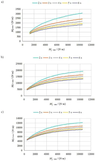
As a result of calculations, the graphic depen-dencies of an electromagnetic moment, a moment in elastic links of the drive system and accelera -tion time of a pumping unit on the maximum fric-tion moment in the air clutch were obtained. The calculations were performed for different values of time of filling the clutch with air. The depen -dencies in Fig. 2 are presented as curves obtained by logarithmic approximation of the results of solving an appropriate system of differential equations of a pumping unit movement.
The calculations of run-up processes were carried out for the pressure on the pumping pis-tons 5 MPa and time of filling the clutch with air 2, 3, 4, 5 and 6 seconds. The value of the fric -tion moment of the air clutch was changed in the range from 1000 (or 500) to 10500 Nm.
Besides, for the cases of loading the pump with the pressure 5 MPa and time of filling the clutch with air 4 s, 5 s and 6 s, we have received graphic dependencies (Fig. 3) of time of a pump -ing unit’s enter-ing into a stable mode on the fric-tion moment in the clutch changed in the range from 1000 to 10000 Nm.
in transmission and root shafts of a pumping unit. An important factor that influences the increase of moments in the mechanism links is time of filling the clutch with air. Distinctively, for small friction moments in the clutch at different time of filling the clutch with air, the electromagnetic moment and moments on the driven pulley of belt drive and a gear of a root shaft of cogged gear are
practically the same. Approximated curves show that when clutch filling lasts 6 s, the bearing con -struction elements of the drive mechanism are be -ing less loaded than in case of clutch fill-ing dur -ing 2 or 3 s. Thus, the carried-out analysis gives grounds to make a conclusion that the time of fill -ing the clutch with air considerably influences the run-up process of a pumping unit.
a)
b)
c)
Fig. 2. Graphic dependencies of the maximum value of the electromagnetic moment (а), the moment in the trans-mission pumping shaft (b) and the moment in the root pumping shaft (c) on the friction moment in the clutch at
CONCLUSIONS
The run-up time of a pumping unit depends directly on the operation of the friction link of a pumping unit. The sliding duration of operating surfaces of the air clutch is defined by the law of a friction moment change in a clutch, which in its turn depends on the time of filling the clutch with air. As evident from the obtained curves, the run-up time of a pumping unit decreases considerably with an increase of the friction moment in the clutch and acceleration of its filling with air. With short duration of filling the clutch with air, there is a possibility of a sharp increase of loading on the elements of the drive mechanism of the pump.
Using the operational friction clutch in the drilling machine pumping unit enables to signifi -cantly reduce dynamic loads of the drive system elements. It was established that due to a little in-creasing of coupling filling time (from 3 to 6 s) allows to reduce the stresses in the drive mecha -nism elements by 20–30%. During the analysis of mathematical modeling results, the rational op-erational parameters of the shaft-air coupling and the moment of friction and the coupling filling time by air were determined. This will provide a sufficiently rapid acceleration of the unit when the dynamic loads on the pump actuator are limited.
REFERENCES
1. Badlani M. and Kleinhenz W. Dynamic Stability of Elastic Mechanisms. Journal of Mechanical
De-2. Christoforou A. and Yigit A. Dynamic model-ing of rotatmodel-ing drill strmodel-ing with borehole interac-tions. Journal of Sound and Vibration, 206(2), 1997, 243–260.
3. Dresig H. and Holzweig F. Dynamics of Machin-ery. Springer, 2010.
4. Erkaya S., Su S., Uzmay I. Dynamic Analysis of a Slider-Crank Mechanism with Eccentric Connec-tor and Planetary Gears. Mechanism and Machine Theory, 42(4), 2007, 393–408.
5. Fung R. F., Chen K. Y., Hsien S. C. Dynamic mod-elling and identification of a slider-crank mecha-nism. Journal of Sound and Vibration, 289(4–5), 2006, 1019–1044.
6. Kharchenko E.V. Dynamical processes of drilling rigs. Svit, 1991.
7. Koser K. A slider-crank mechanism based robot arm performance and dynamic analysis. Mecha-nism and Machine Theory, 39(2), 2004, 169–182. 8. Mudrik I. Measurement of dynamic properties of
machine aggregate with variable parameters and asynchronous motor. Journal of Theoretical and Applied Mechanics, 23(1), 1992, 40–41.
9. Patel R. S., Patel D. S., Patel B. D. A Review on Kinematic and Dynamic Analysis of Mechanism. International Journal of Engineering Science and Innovative Technology, 2(2), 2013, 338–341. 10. Viscomi B. V. and Arye R. S. Nonlinear dynamic
response of elastic slider crank mechanism. Journal of Engineering for Industry, 93(1), 1971, 251–262. 11. Yutaev V. G. Dynamics of drilling rigs. Nedra,
1987.
12. Zhu H. T., Zhang X., Zhang J. T., Hu S. H. Dynam-ic simulation of a smart crank and slider mecha-nism. Journal of Marine Science and Application,