DIN EN ISO9001:2008 certified
ADDI-DATA GmbH
Airpark Business Center
Airport Boulevard B210
77836 Rheinmünster
Germany
Phone: +49 7229 1847–0
Fax: +49 7229 1847–222
E-mail: [email protected]
www.addi-data.com
Technical description
APCI-2200
Relay board, optically isolated
Product information
This manual contains the technical installation and important instructions for correct commissioning and usage, as well as production information according to the current status before printing.
The content of this manual and the technical product data may be changed without prior notice. ADDI-DATA GmbH reserves the right to make changes to the technical data and the materials included herein.
Warranty and liability
The user is not permitted to make changes to the product beyond the intended use, or to interfere with the product in any other way.
ADDI-DATA shall not be liable for obvious printing and phrasing errors. In addition, ADDI DATA, if legally permissible, shall not be liable for personal injury or damage to materials caused by improper installation and/or commissioning of the product by the user or improper use, for example, if the product is operated despite faulty safety and protection devices, or if notes in the operating instructions regarding transport, storage, installation, commissioning, operation, thresholds, etc. are not taken into consideration. Liability is further excluded if the operator changes the product or the source code files without authorisation and/or if the operator is guilty of not monitoring the permanent operational capability of working parts and this has led to damage.
Copyright
This manual, which is intended for the operator and its staff only, is protected by copyright. Duplication of the information contained in the operating instructions and of any other product information, or disclosure of this information for use by third parties, is not permitted, unless this right has been granted by the product licence issued. Non-compliance with this could lead to civil and criminal proceedings. ADDI-DATA software product licence
Please read this licence carefully before using the standard software. The customer is only granted the right to use this software if he/she agrees with the conditions of this licence.
The software must only be used to set up the ADDI-DATA products.
Reproduction of the software is forbidden (except for back-up and for exchange of faulty data carriers). Disassembly, decompilation, decryption and reverse engineering of the software are forbidden. This licence and the software may be transferred to a third party if this party has acquired a product by purchase, has agreed to all the conditions in this licence contract and the original owner does not keep any copies of the software.
Trademarks
• ADDI-DATA, APCI-1500, MSX-Box and MSX-E are registered trademarks of ADDI-DATA GmbH.
• Turbo Pascal, Delphi, Borland C, Borland C++ are registered trademarks of Borland Software Corporation.
• Microsoft .NET, Microsoft C, Visual C++, MS-DOS, Windows 2000, Windows XP, Windows Vista, Windows 7, Windows Server 2000, Windows Server 2003, Windows Embedded and Internet Explorer are registered trademarks of Microsoft Corporation.
• LabVIEW, LabWindows/CVI, DASYLab, DIAdem are registered trademarks of National Instruments Corporation.
• CompactPCI is a registered trademark of PCI Industrial Computer Manufacturers Group.
• VxWorks is a registered trademark of Wind River Systems, Inc.
Warning!
The following risks result from the improper implementation of the board and from use contrary to the regulations:
Personal injury
Damage to the board, the PC and peripherals
Pollution of the environment.
Protect yourself, others and the environment!
Read the safety precautions (yellow leaflet) carefully! If this leaflet is not enclosed with the documentation, please contact us and ask for it.
Observe the instructions of this manual!
Make sure that you do not forget or skip any step! We are not liable for damages resulting from the wrong use of the board.
Pay attention to the following symbols:
NOTICE!
Designates hints and other useful information.
NOTICE!
Designates a possibly dangerous situation. If the instructions are ignored, the board, the PC and/or peripherals may be destroyed.
WARNING!
Designates a possibly dangerous situation. If the instructions are ignored, the board, the PC and/or peripherals may be destroyed and persons may be endangered.
APCI-2200 Contents
WARNING!...3
1
DEFINITION OF APPLICATION ...6
1.1 Intended use ...6 1.2 Usage restrictions...6 1.3 Limits of use...6 1.4 General description ...72
USER ...8
2.1 Qualification ...8 2.2 Country-specific regulations ...83
HANDLING OF THE BOARD...9
4
TECHNICAL DATA...10
4.1 Electromagnetic compatibility (EMC) ...10
4.2 Physical set-up of the board...10
4.3 Versions ...11
4.4 Limit values...11
5
INSTALLATION OF THE BOARD ...14
5.1 Opening the PC...14
5.2 Selecting a free slot ...14
5.3 Plugging the board into the slot ...15
5.4 Closing the PC ...15
6
DRIVER INSTALLATION...16
6.1 Questions and updates...16
7
CONNECTING THE PERIPHERALS...17
7.1 Connection to the digital inputs ...17
7.2 Pin assignment...18
7.2.1 APCI-2200-16-8 ...18
7.2.2 APCI-2200-8-8 ...19
7.3 Connecting the relay outputs ...19
7.4 Protective circuit at the load (examples) ...20
7.5 Connection examples...21
APCI-2200 Contents
8.1 Block diagram...23
8.2 Relay outputs ...23
8.3 Watchdog...23
8.4 Digital inputs (option)...24
9
STANDARD SOFTWARE ...25
10
RETURN OR DISPOSAL ...26
10.1 Return ...26
10.2 Disposal of ADDI-DATA waste equipment...27
11
INDEX ...28
Figures
Fig. 3-1: Correct handling ...9Fig. 5-1: PCI slot types ...14
Fig. 5-2: Inserting the board ...15
Fig. 5-3: Fastening the board at the back cover ...15
Fig. 7-1: Connection of relay outputs through 50-pin connector...18
Fig. 7-2: Connection of digital inputs through FB2200-3 ...18
Fig. 7-3: Connection of inputs/outputs through 50-pin connector ...19
Fig. 7-4: Switching principle of the relay outputs ...19
Fig. 7-5: Connecting the relay outputs (example)...20
Fig. 7-6: Connection of the screw terminal panels PX8001 and PX901-ZG...21
Fig. 7-7: Connection of the screw terminal panel PX8001...22
Fig. 8-1: Block diagram ...23
Fig. 8-2: Input circui...24
Fig. 10-1: Serial number ...26
APCI-2200 Definition of application
1
DEFINITION OF APPLICATION
1.1
Intended use
The APCI-2200 board must be inserted in a PC with PCI 5V/32-bit slots which is used as electrical equipment for measurement, control and laboratory pursuant to the norm EN 61010-1 (IEC 61010-1). The used personal computer (PC) must fulfil the requirements of IEC 60950-1 or EN 60950-1 and EN 55022 or IEC/CISPR 22 and EN 55024 or IEC/CISPR 24.
The use of the board APCI-2200 in combination with external screw terminal panels requires correct installation according to the series IEC 61439 or EN 61439 (Low-voltage switchgear and controlgear assemblies).
1.2
Usage restrictions
The APCI-2200 board must not be used as a safety-related part (SRP). The board must not be used for safety-related functions, for example for emergency stop functions.
The APCI-2200 board must not be used in potentially explosive atmospheres.
The APCI-2200 board must not be used as electrical equipment according to the Low Voltage Directive 2006/95/EC.
1.3
Limits of use
All safety information and the instructions in the manual must be followed to ensure proper intended use.
Uses of the board beyond these specifications are considered as improper use. The manufacturer is not liable for damages resulting from improper use.
The board must remain in its anti-static packaging until it is installed. Please do not delete the identification numbers of the board or the warranty claim will be invalid.
APCI-2200 Definition of application
1.4
General description
The board has up to 8 digital inputs and up to 16 relay outputs for processing digital 24 V signals.
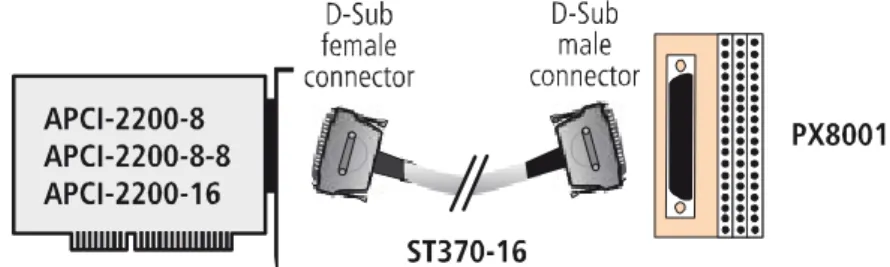
The connection with our standard cables ST010 and ST370-16 complies with the specifications:
- metallised plastic hoods - shielded cable
APCI-2200 User
2
USER
2.1
Qualification
Only persons trained in electronics are entitled to perform the following works: - installation - commissioning - use - maintenance
2.2
Country-specific regulations
Consider the country-specific regulations about: - the prevention of accidents- electrical and mechanical installations - Electromagnetic compatibility (EMC).
APCI-2200 Handling of the board
3
HANDLING OF THE BOARD
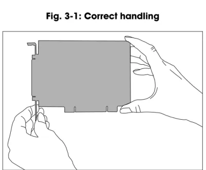
Fig. 3-1: Correct handling
Hold the board cautiously at the outer end and at the slot bracket. Do not touch the surface of the board!
APCI-2200 Technical data
4
TECHNICAL DATA
4.1
Electromagnetic compatibility (EMC)
The board APCI-2200 is suited for installation in personal computers (PCs) which comply with the European EMC directive.
The board APCI-2200 complies with the European EMC directive.
The tests were carried out by a certified EMC laboratory in accordance with the norm from the EN 61326 series (IEC 61326). The limit values as set out by the European EMC directive for an industrial environment are complied with.
The respective EMC test report is available on request.
4.2
Physical set-up of the board
Dimensions:
Dimensions (L x W):……….. 131 x 99 mm Weight: ... approx. 160 g
Installation in: ... 32/64-bit PCI slot 5 V
Connection to the peripherals: ... 50-pin D-Sub male connector 37-pin header for ribbon cable Accessories1:
Standard cable: ... ST370-16, ST010/ST011 Ribbon cable: ... FB2200-3 for the digital inputs Screw terminal panel: ... PX901-ZG, PX8001
NOTICE!
The connection lines must be installed in such a way that they are protected against mechanical loads.
1 Not included in the standard delivery.
APCI-2200 Technical data
4.3
Versions
The relay board APCI-2200 is available in the following versions: Version Full version Partial
assembly Relay outputs Digital inputs APCI-2200-16-8 9 16 8 APCI-2200-16 9 16 - APCI-2200-8 9 8 - APCI-2200-8-8 9 8 8
4.4
Limit values
Max. altitude: ... 2000 mOperating temperature: ... 0 to 60°C (with forced ventilation)
Storage temperature: ... -25 to 70°C Relative humidity at indoor installation
50% at +40 °C 80% at +31 °C
Minimum PC requirements:
Bus speed: < 33 MHz
Operating system: ... Windows 7, Vista (32-bit), XP,
2000, Linux
Energy requirements:
- Operating voltage of the PC: ... 5 V ± 5%
- Current consumption (without load): ... typ. see table ± 10%
APCI-2200-16-8 APCI-2200-8-8 APCI-2200-16 APCI-2200-8
+ 5 V from PC 510 mA 290 mA 480 mA 264 mA
Required slots
APCI-2200 Technical data
APCI-2200-8-8, APCI-2200-16,
APCI-2200-8: ...1 Addressing
Data bus access: ... 8-bits
Required address ranges: ... 4 bytes (1 Dword) 32 bytes (8 Dword) Digital inputs
Input type: ... ground-related inputs Number of inputs: ... 8
Nominal voltage: ... 12 - 24 VDC Input current at nominal voltage: ... approx. 6 mA
Logical input level (standard): ... UH1 max.: 30 V / 7 mA typ.
UH min.: 9 V / 4 mA typ.
UL2
max.: 6 V / 2.3 mA typ.
UL min.: 0 V
Signal delay: ... 70 μs (at nominal voltage) Maximal input frequency: ... 5 kHz (at nominal voltage) Relay data
Types of contacts: ... change-over contacts Max. switching voltage3: ... 60 VDC, 48 VAC Max. switching current: ... 1 A
Max. switching capacity: ... 62.5 VA, 30 W
Min. permissible load: ... 1 mA, 5 VDC Nominal load: ... 1 A, 24 VDC Contact resistance: ... < 100 mΩ
Contact material: ... Ag and Au-plated Contact force, working/rest side: ... 15/15 cN
Responding time: ... max 5 ms, typ. 2.5 ms
1 UH: input voltage, logic "1" 2
UL: input voltage, logic "0"
APCI-2200 Technical data
Release time: ... max 5 ms, typ. 0.9 ms Mechanical life: ... 5 x 10⁶ operations Electrical life at nominal load: ... 105 operations
Creeping distance and corresponding voltage values according to DIN VDE 0110, with stain degree 1 (clean board) Between the coil and the contacts and
between the contacts: ... 800 V between the contacts: ... 200 V Test voltage for the relays
1000 VAC, 50/60 Hz 1 minute between the coil and the contacts 400 VAC, 50/60 Hz 1 minute between the open contact
APCI-2200 Installation of the board
5
INSTALLATION OF THE BOARD
Risk of injury!
Please follow the safety precautions! An improper handling of the board may cause property damage and injury.
5.1
Opening the PC
♦ Switch off your PC and all the units connected to the PC ♦ Pull the PC mains plug from the socket.
♦ Open your PC as described in the manual of the PC manufacturer.
5.2
Selecting a free slot
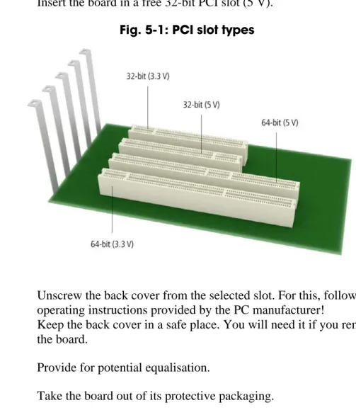
♦ Insert the board in a free 32-bit PCI slot (5 V).
Fig. 5-1: PCI slot types
♦ Unscrew the back cover from the selected slot. For this, follow the operating instructions provided by the PC manufacturer!
Keep the back cover in a safe place. You will need it if you remove the board.
♦ Provide for potential equalisation.
APCI-2200 Installation of the board
5.3
Plugging the board into the slot
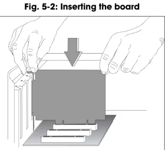
♦ Insert the board vertically into the chosen slot.Fig. 5-2: Inserting the board
♦ Fasten the board to the rear of the PC housing with the screw which was fixed on the back cover.
Fig. 5-3: Fastening the board at the back cover
♦ Tighten all loose screws.
5.4
Closing the PC
APCI-2200 Driver installation
6
DRIVER INSTALLATION
Information on how to select and download the appropriate driver can be found in the document “Quick installation PC boards” (see PDF link). The installation of drivers of the type “ADDI-DATA Multiarchitecture Device Drivers 32-/64-Bit for x86/AMD64” as well as the installation of the corresponding samples is described in the installation instructions (see PDF link).
6.1
Questions and updates
If you have any questions, do not hesitate to call us or to send us an e-mail: Phone: +49 7229 1847-0
E-mail: [email protected]
Manual and software download from the Internet
The latest versions of the technical manual and the standard software for the board APCI-2200 can be downloaded for free at: www.addi-data.com
NOTICE!
Before using the board and in case of malfunction during operation, check if there is an update (manual, driver) available. Current data can be found on our website or contact us directly.
APCI-2200 Connecting the peripherals
7
CONNECTING THE PERIPHERALS
Risk of death!
The relay board may work with dangerous currents. Improper operation is dangerous to life!
♦ Turn off the mains supply. ♦ Pull the mains plug.
♦ Disconnect all cables to external devices.
NOTICE!
Make sure that the wire cross section of the connection cable accepts the operating current.
7.1
Connection to the digital inputs
Version 16-8: To connect the peripherals to the digital inputs, the ribbon cable FB2200-3 is required.
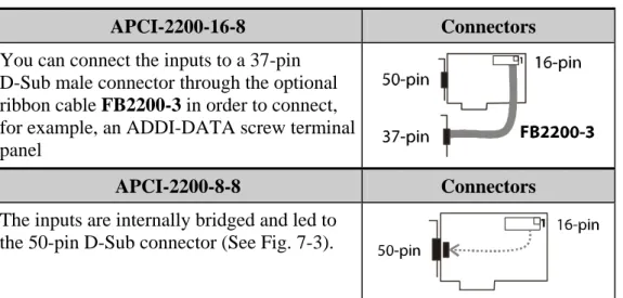
Table 7-1: Connection to the digital inputs
APCI-2200-16-8 Connectors You can connect the inputs to a 37-pin
D-Sub male connector through the optional ribbon cable FB2200-3 in order to connect, for example, an ADDI-DATA screw terminal panel
APCI-2200-8-8 Connectors The inputs are internally bridged and led to
APCI-2200 Connecting the peripherals
7.2
Pin assignment
7.2.1
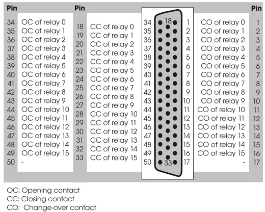
APCI-2200-16-8
Fig. 7-1: Connection of relay outputs through 50-pin connector
APCI-2200 Connecting the peripherals
7.2.2
APCI-2200-8-8
Fig. 7-3: Connection of inputs/outputs through 50-pin connector
7.3
Connecting the relay outputs
APCI-2200 Connecting the peripherals
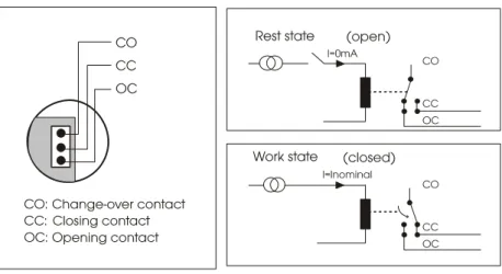
Fig. 7-5: Connecting the relay outputs (example)
OC CO CC
Load
VCC
Excited relay:
The operating voltage (VCC) is connected to the load through the closing contact.
Relay not excited:
The load is isolated from the mains supply.
7.4
Protective circuit at the load (examples)
NOTICE!
Overloading the relays by connecting ohmic, inductive or capacitive loads without protective circuits can damage a relay or cause a premature wear-out.
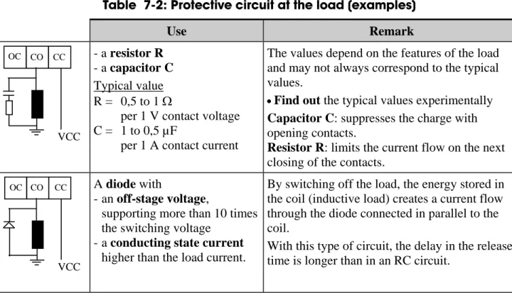
Table 7-2: Protective circuit at the load (examples)
Use Remark OC CO CC VCC - a resistor R - a capacitor C Typical value R = 0,5 to 1 Ω
per 1 V contact voltage C = 1 to 0,5 µF
per 1 A contact current
The values depend on the features of the load and may not always correspond to the typical values.
•Find out the typical values experimentally Capacitor C: suppresses the charge with opening contacts.
Resistor R: limits the current flow on the next closing of the contacts.
OC CO CC
VCC
A diode with
- an off-stage voltage,
supporting more than 10 times the switching voltage
- a conducting state current higher than the load current.
By switching off the load, the energy stored in the coil (inductive load) creates a current flow through the diode connected in parallel to the coil.
With this type of circuit, the delay in the release time is longer than in an RC circuit.
APCI-2200 Connecting the peripherals
Use Remark
OC CO CC
VCC
- a Zener diode The off-state voltage should correspond to the mains voltage
This circuit shortens the release time for applications in which the release time of the protective circuit with diode would be too slow.
OC CO CC
VCC
- a varistor The constant voltage effect of the varistor does not allow high voltages at the contacts.
With this protective circuit, the release time is only slightly delayed.
7.5
Connection examples
Fig. 7-6: Connection of the screw terminal panels PX8001 and PX901-ZG
NOTICE!
Plug the FB2200-3 cable into the connector by inserting the red (or blue or black) cable line into pin 1.
APCI-2200 Connecting the peripherals
APCI-2200 Functions of the board
8
FUNCTIONS OF THE BOARD
8.1
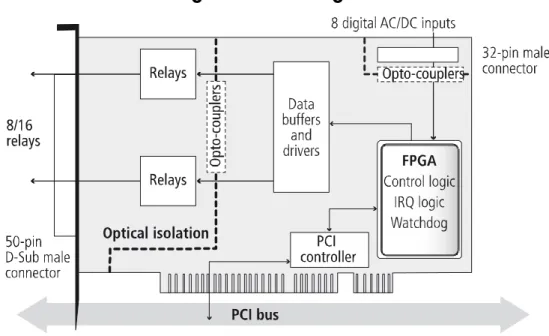
Block diagram
Fig. 8-1: Block diagram
8.2
Relay outputs
The switching position of the relays 0-7 or 8-15 can be modified simultaneously as long as the watchdog is not in alarm state.
8.3
Watchdog
The watchdog is a downward counter, which resets the digital outputs after the reload value has run down (timeout).
The watchdog can have 3 different status:
"OFF": The watchdog is switched off and has no influence on the relays. "ON": The watchdog has been switched on by software trigger.
It is supervising the program course and monitoring the status of the relays by timeout.
"Alarm": The watchdog signals an alarm by resetting all outputs. The watchdog status can be read back at any time through software. Time intervals can be programmed from 20 ms to 5s in 20 ms steps.
APCI-2200 Functions of the board
8.4
Digital inputs (option)
This function is available for the versions APCI-2200-16-8 and APCI-2200-8-8.
The inputs acquire the status of external signals: the input information is stored through software as a value in the memory cell of the PC. This value is converted to give the status of the input signals.
24 V opto-isolated inputs (IEC1131-2):
- logic "1" corresponds to an input voltage > 8 V - logic "0" corresponds to an input voltage < 6 V.
The required current per input is 6 mA at nominal voltage.
NOTICE!
If you operate all inputs with the same voltage supply, the voltage supply must deliver at least 32 x 6 mA = 192 mA at Vcc ext. = 24 V.
The maximum input voltage is 30 V / 7 mA typical.
The input signals are filtered by transil diodes, Z diodes, LC filters and optical couplers. The effects of inductive and capacitive noise are thus reduced.
The board requires no initialisation to read the 24 V digital input
information. After successful power ON, data is immediately available on the board.
APCI-2200 Standard software
9
STANDARD SOFTWARE
The API software functions supported by the board are listed in an HTML document. A description on how to access the respective file can be found in the document “Quick installation PC boards” (see PDF link), in the chapter “Standard software”.
APCI-2200 Return or disposal
10
RETURN OR DISPOSAL
10.1
Return
If you need to return your board, you should read the following checklist before.
Checklist for returning the board:
• Specify the reason for returning your board (e.g. exchange,
modification, repair), the serial number of the board, the contact person in your company including his/her telephone extension and e-mail address, as well as the mailing address for a potential new delivery. You do not have to indicate the RMA number.
Fig. 10-1: Serial number
• Note down the serial number of the board.
• Place the board in an ESD protective cover. Then pack it in a cardboard box so that it is well-protected for shipping. Send the packed board together with your details to:
ADDI-DATA GmbH Airpark Business Center Airport Boulevard B210 77836 Rheinmünster Germany
• If you have any questions, do not hesitate to contact us: Phone: +49 7229 1847-0
APCI-2200 Return or disposal
10.2
Disposal of ADDI-DATA waste equipment
ADDI-DATA organises the disposal of ADDI-DATA products that were put on the German market after 13 August 2005.
If you want to return waste equipment, please e-mail your request to:
Boards that were delivered after 13 August 2005 can be recognised by the following label:
Fig. 10-2: Disposal: Label
This symbol indicates the disposal of waste electrical and electronic equipment. It is valid in the European Union and in other European countries that have a separate collection system. Products carrying this symbol must not be treated as household waste.
For more detailed information on the recycling of these products, please contact your local citizens’ office, your household waste collection service, the shop where you bought this product or the distributor you purchased this product from.
If you dispose of this product correctly, you will help to prevent damage that could be caused to the environment and to human health by
inappropriate disposal. The recycling of materials will help to conserve our natural resources.
Disposal in other countries than Germany
APCI-2200 Index
11
INDEX
Accessories 10 Connection cables 17 Application 6 Block diagram 23 Connection examples 21 creeping distance 13 Digital inputs (option)Function description 24 Dimensions 10 Disposal 27 driver installation 16 EMC Electromagnetic compatibility 10 Energy requirements 11 Handling 9 Input circuit 24 Inputs Limit values 12 Installation of the board 14 Intended use 6 Limit values 11 Limits of use 8 Pin assignment 18 Relay Limit values 12 Relay outputs Connection 19 Repair 26 Return 26 Slots 14 Standard software 25 Technical data 10 Update Driver 16 Manual 16 Updates 16 User Qualification 8 Versions 11 Watchdog 23 Weight 10