Physically Dense Server Architectures
by
Anthony Thomas Gutierrez
A dissertation submitted in partial fulfillment of the requirements for the degree of
Doctor of Philosophy
(Computer Science and Engineering) in The University of Michigan
2015
Doctoral Committee:
Professor Trevor N. Mudge, Chair Professor David T. Blaauw
Assistant Research Scientist Ronald G. Dreslinski Jr. Assistant Professor Jason O. Mars
c
Anthony Thomas Gutierrez 2015 All Rights Reserved
ACKNOWLEDGEMENTS
First and foremost I would like to thank my advisor Trevor Mudge, without whom this thesis would not be possible. His laid back style allowed me to explore research topics for myself, however he was always there to provide feedback, guidance, equip-ment, and whatever else I needed. Being a student of Trev’s I was able to travel to conferences, collaborate with industry leaders on interesting projects, work with well-respected academic researchers at Michigan as well as other top universities, and enjoy many lunches at Casey’s. Ronald Dreslinski was also a big help to me going back to the first day I joined Trev’s research group, when he was still a fellow stu-dent. He became like a co-advisor for all of us in the (Trev + Ron) TRON group. I also had the pleasure to work with Thomas Wenisch on several projects during my graduate career. Tom’s encyclopedic knowledge and ability to explain things simply was always useful. In addition I would like to thank the remaining members of my committee: Jason Mars and David Blaauw, who provided me with valuable feedback on this dissertation.
I would be remiss if I didn’t acknowledge my fellow TRON group lab members over the years: Nilmini Abeyratne, Geoff Blake, Yajing Chen, Mike Cieslak, Cao Gao, Johann Hauswald, Yiping Kang, Tom Manville, Mark Woh, and Mr. Qi Zheng. We had some good times together.
There were many friends who helped keep me sane throughout my graduate career, and special thanks goes out to them. Joe Pusdesris and I formed what will be a lifelong friendship as soon as he joined the TRON group as an undergrad—earning him the
moniker ”UG” Joe. Whether it was eating sloppy chili dogs at C-Reds, or checking out some local concerts, UG and I always had a good time. Lots of good food, beer, and conversation were had with Matt Burgess, Jason Clemons, Joe Greathouse, Rick Hollander, Dave Meisner, and Andrea Pellegrini. Korey Sewell took me under his wing when I first joined Trev’s group and we quickly became friends, playing pickup basketball a few times a week, and tailgating with the rest of the game day crew on football Saturdays. And not to forget the rest of the game day crew, I must thank Ced Armand, Kevin ”Sleep” Carter, Lou Gilling, and Chuck Sutton. We had a lot of memorable times over the years, and I’m looking forward to a lot more.
To my girlfriend Alyssa Doffing, thanks for sticking by me throughout this entire process. It’s finally over.
Finally I thank my family for all of their love and support. First I must thank my mother Cheryl Gutierrez, whose love and sacrifice inspired me to become the person I am today. My grandmother Theresa Coutinho is one of the most kind and hard working people I have ever met, without her support I would not have made it this far. My brother Carlos Gutierrez and my sister Chelsea Gutierrez were always there for me no matter how hard times got. I love you all.
TABLE OF CONTENTS
DEDICATION . . . ii
ACKNOWLEDGEMENTS . . . iii
LIST OF FIGURES . . . viii
LIST OF TABLES . . . x
LIST OF ABBREVIATIONS . . . xi
ABSTRACT . . . xiii
CHAPTER I. Introduction . . . 1
1.1 Scaling in the Cloud . . . 2
1.2 Data Center Trends . . . 4
1.2.1 Opportunities for Improved Efficiency . . . 5
1.3 Contributions of this Dissertation . . . 7
II. Background . . . 11 2.1 TCP/IP Networking . . . 11 2.1.1 Application Layer . . . 11 2.1.2 Transport Layer . . . 13 2.1.3 Internet Layer . . . 13 2.1.4 Link Layer . . . 14
2.2 RDMA over InfiniBand . . . 15
2.3 Near-Data Compute . . . 16
2.3.1 Processing in Memory . . . 16
2.3.2 3D-Stacked Memory Technology . . . 17
3.1 Background . . . 19
3.1.1 Cloud Computing Design . . . 19
3.1.2 Scaling in the Cloud . . . 20
3.1.3 Memcached . . . 21
3.2 Related Work . . . 22
3.2.1 Characterizing Cloud Workloads . . . 22
3.2.2 Efficient 3D-Stacked Servers . . . 23
3.2.3 Non-Volatile Memory File Caching in Servers . . . . 23
3.2.4 Super Dense Servers . . . 24
3.2.5 McDipper . . . 24
3.2.6 Enhancing the Scalability of Memcached . . . 24
3.2.7 TSSP . . . 25
3.2.8 Resource Contention in Distributed Hash Tables . . 25
3.2.9 TILEPro64 . . . 26
3.2.10 FAWN . . . 26
3.3 Mercury and Iridium . . . 26
3.3.1 Mercury . . . 27 3.3.2 Iridium . . . 31 3.4 Methodology . . . 32 3.4.1 Memcached . . . 33 3.4.2 Simulation Infrastructure . . . 33 3.4.3 TPS calculation . . . 34 3.4.4 Power Modeling . . . 35 3.4.5 Area . . . 36 3.4.6 Density . . . 36 3.5 Results . . . 37 3.5.1 Request Breakdown . . . 37
3.5.2 3D-Stack Memory Access Latency Sensitivity . . . . 39
3.5.3 Density and Throughput . . . 45
3.5.4 Power and Throughput . . . 48
3.5.5 Cooling . . . 49
3.5.6 Comparison to Prior Work . . . 49
3.6 Conclusion . . . 50
IV. Integrated Networking for Dense Servers . . . 52
4.1 Introduction . . . 52
4.2 A Case for Physically Dense Servers . . . 54
4.2.1 Warehouse-Scale Computing . . . 55
4.3 KeyVault . . . 55
4.3.1 Mercury . . . 56
4.3.2 3D-Stack Technology . . . 57
4.3.3 KeyVault . . . 58
4.4.2 Communication Protocol . . . 62
4.5 Experimental Methodology . . . 64
4.5.1 Key-Value Store Software . . . 64
4.5.2 Memcached Client . . . 65 4.5.3 Simulation Infrastructure . . . 65 4.5.4 Operating System . . . 66 4.5.5 Power Modeling . . . 66 4.5.6 Area Estimation . . . 67 4.5.7 Cooling . . . 70 4.6 Results . . . 70 4.6.1 Request Throughput . . . 71 4.6.2 Request Latency . . . 71
4.6.3 Network Link Bandwidth . . . 73
4.6.4 Memory Bandwidth . . . 74
4.6.5 Maximum 1.5U Server Performance . . . 76
4.6.6 Comparison to Prior Works . . . 77
4.7 Related Work . . . 79
4.7.1 Improving Key-Value Stores . . . 79
4.7.2 Remote Memory Access . . . 80
4.7.3 Integrated Networking . . . 81
4.7.4 Scale-Out Server Design . . . 81
4.8 Conclusion . . . 82
V. Conclusion . . . 84
5.1 Future Research Directions . . . 85
LIST OF FIGURES
Figure
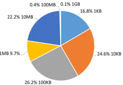
1.1 File size distribution of files stored by a typical user. . . 2
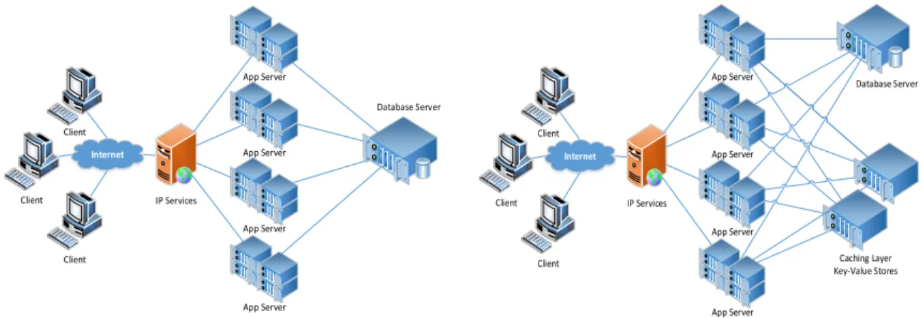
1.2 Two different models for web servers. . . 3
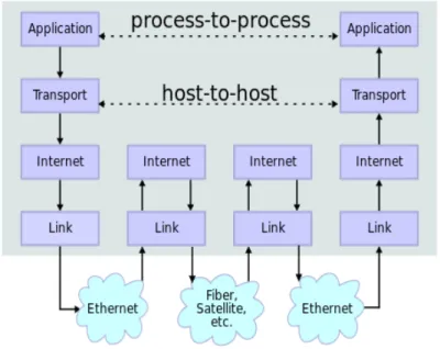
2.1 Network layers for the TCP/IP model. . . 12
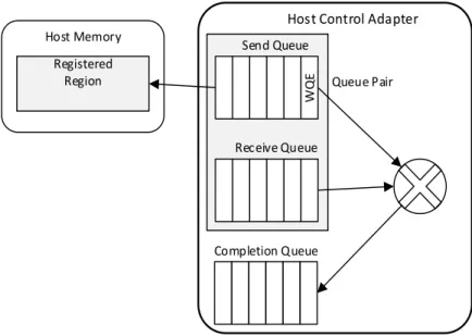
2.2 The work queues inside an HCA adapter. . . 15
2.3 A high-level overview of Micron’s Hybrid Memory Cube technology. 17 3.1 Configurations with 2 and 3 layers behind a vip to service web requests. 19 3.2 A Mercury server and a single stack. A Mercury stack is made up of 8 DRAM layers, each 15.5mm×18mm, stacked with a logic layer containing the processing elements, DRAM peripheral logic, and NIC MAC & buffers. These stacks are then placed in a 400-pin BGA package. The 1.5U enclosure is limited to 96 Ethernet ports, each of which will be connected to a Mercury stack. Therefore, 96 Mercury stacks and 48 Dual NIC PHY chips are placed in the 1.5U enclosure. Due to space limitations a separate diagram of Iridium is omitted, however the high-level design is similar—the only difference being that we use a single layer of 3D-stacked Flash for the Iridium design. 27 3.3 Logical organization and physical floorplan of the 3D DRAM. . . . 30
3.4 GET execution time. . . 38
3.5 SET execution time. . . 38
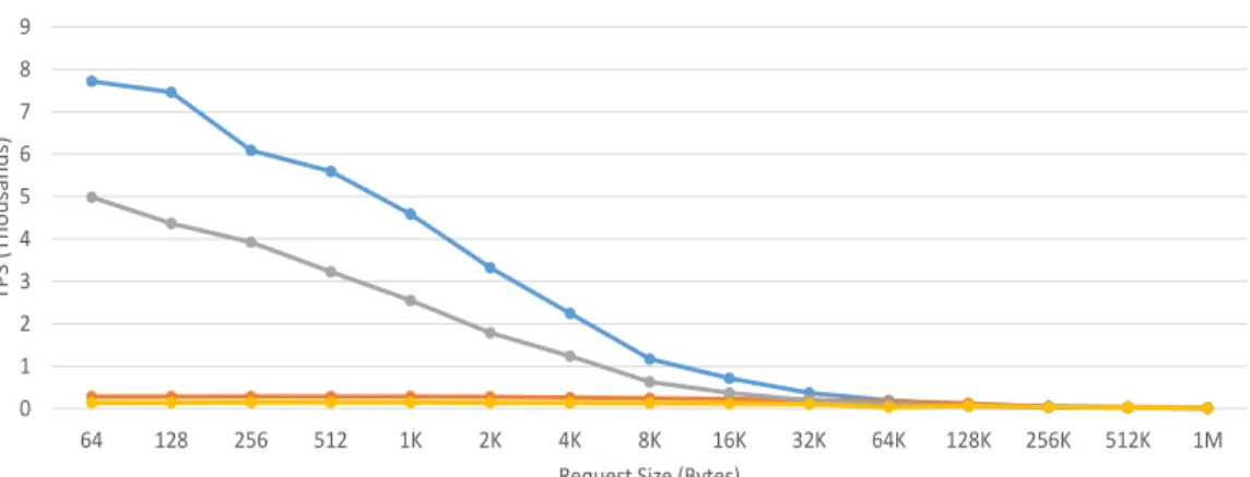
3.6 TPS for an A15-@1GHz-based Mercury stack with a 2MB L2 cache. 40 3.7 TPS for an A15-@1GHz-based Mercury stack with no L2 cache. . . 40
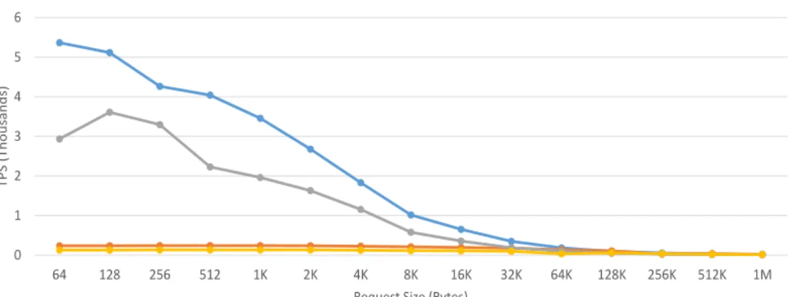
3.8 TPS for an A7-based Mercury stack with a 2MB L2 cache. . . 41
3.9 TPS for an A7-based Mercury stack with no L2 cache. . . 41
3.10 TPS for an A15-@1GHz-based Iridium stack with a 2MB L2 cache. 42 3.11 TPS for an A15-@1GHz-based Iridium stack with no L2 cache. . . . 42
3.12 TPS for an A7-based Iridium stack with a 2MB L2 cache. . . 43
3.13 TPS for an A7-based Iridium stack with no L2 cache. . . 43
3.14 Density and throughput for Mercury stacks servicing 64B GET re-quests. . . 46 3.15 Density and throughput for Iridium stacks servicing 64B GET requests. 46 3.16 Power and throughput for Mercury stacks servicing 64B GET requests. 47 3.17 Power and throughput for Iridium stacks servicing 64B GET requests. 47
4.1 1.5U Server configuration for Mercury and KeyVault servers. By re-ducing the need for complex networking hardware, a KeyVault server can fit more memory and compute into a single 1.5U server box than
a Mercury server while improving throughput and latency. . . 54
4.2 The components of a KeyVault server in detail. . . 56
4.3 The HW/SW interface of the integrated NIC. . . 60
4.4 Average RPS vs. attempted RPS for the FriendFeed workload. . . . 68
4.5 Average RPS vs. attempted RPS for the MicroBlog workload. . . . 68
4.6 Average request latency vs. attempted RSP for the FriendFeed work-load. . . 69
4.7 Average request latency vs. attempted RSP for the MicroBlog work-load. . . 69
4.8 95% Latency vs. attempted RSP for FriendFeed and MicroBlog on KeyVault. . . 70
4.9 Percentage of time spent in the networking stack, performing the hash computation, or executing miscellaneous Memcached code on average for a single request. . . 72
4.10 95% Latency vs. attempted RSP for FriendFeed and MicroBlog on KeyVault. . . 73
4.11 Sustained network bandwidth for the FriendFeed workload. . . 74
4.12 Sustained memory bandwidth for the FriendFeed workload. . . 75
4.13 Sustained memory bandwidth for the MicroBlog workload. . . 75
LIST OF TABLES
Table
3.1 Power and area for the components of a 3D stack. . . 29 3.2 Comparison of 3D-stacked DRAM to DIMM packages. . . 29 3.3 Power and area comparison for 1.5U maximum configurations. For
each configuration we utilize the maximum number of stacks we can fit into a 1.5U server, which is 96, or until we reach our power budget of 750W. The power and bandwidth numbers are the maximum values we observed when servicing requests from 64B up to 1MB. . . 33 3.4 Comparison of Mercury and Iridium to prior art. We compare several
versions of Mercury and Iridium (recalln is the number of cores per stack) to different versions of Memcached running on a state-of-the-art server, as well as TSSP. The bold values represent the highest density (GB), efficiency (TPS/W), and accessibility (TPS/GB). . . 49 4.1 Per component descriptions for a KeyVault cluster. . . 62 4.2 Comparison of various KeyVault and Mercury server configurations.
A single KeyVault server is able to provide 2× the throughput of a Mercury server. Memory density is improved over a Mercury server by 50%. This improved performance comes while simultaneously im-proving power and bandwidth efficiency. . . 77 4.3 Comparison of KeyVault to several prior works. . . 77
LIST OF ABBREVIATIONS
ARP address resolution protocol
BGA ball grid array
CQ completion queue
DHT distributed hash table
DMA direct memory access
HCA host channel adapter
HMC Hybrid Memory Cube
IP internet protocol
KVD key-value distributor
LRG least-recently-granted
NIC network interface controller
OoO out-of-order
PHY physical
QoS quality of service
QP queue pair
RDMA remote direct memory access
RPS requests per second
RTT round-trip time
Rx receive
SoC system on a chip
TCP transport control protocol
TSV through-silicon via
Tx transmit
VIP virtual IP
ABSTRACT
Physically Dense Server Architectures by
Anthony Thomas Gutierrez
Chair: Trevor N. Mudge
Distributed, in-memory key-value stores have emerged as one of today’s most impor-tant data center workloads. Being critical for the scalability of modern web services, vast resources are dedicated solely to key-value stores in order to ensure that quality of service guarantees are met. These resources include: many server racks to store terabytes—possibly petabytes—of key-value data, the power necessary to run all of the machines, networking equipment and bandwidth, and the data center warehouses used to house the racks.
There is, however, a mismatch between the key-value store software and the com-modity servers on which it is run, leading to inefficient use of resources. The primary cause of this inefficiency is the overhead incurred from processing individual network packets, which typically carry small payloads of less than a few kilobytes, and require minimal compute resources. Thus, one of the key challenges as we enter the exascale era is how to best adjust to the paradigm shift from compute-centric data centers, to storage-centric data centers.
This dissertation presents a hardware/software solution that addresses the in-efficiency issues present in the modern data centers on which key-value stores are
currently deployed. First, it proposes two physical server designs, both of which use 3D-stacking technology and low-power CPUs to improve density and efficiency. The first 3D architecture—Mercury—consists of stacks of low-power CPUs with 3D-stacked DRAM, as well as NICs. The second architecture—Iridium—replaces DRAM with 3D NAND Flash to improve density.
The second portion of this dissertation proposes and enhanced version of the Mer-cury server design—called KeyVault—that incorporates integrated, zero-copy net-work interfaces along with an integrated switching fabric. In order to fully utilize the integrated networking hardware, as well as reduce the response time of requests, a custom networking protocol is proposed. Unlike prior works on accelerating key-value stores—e.g., by completely bypassing the CPU and OS when processing requests— this work only bypasses the CPU and OS when placing network payloads into a process’ memory. The insight behind this is that because most of the overhead comes from processing packets in the OS kernel—and not the request processing itself— direct placement of packet’s payload is sufficient to provide higher throughput and lower latency than prior approaches. The need for complex hardware or software is also eliminated.
CHAPTER I
Introduction
We have now entered into an era with unprecedented amounts of data stored in the cloud. A recent research report from Nasuni estimates that there is now over one exabyte of data stored in the cloud [69], while Facebook reports an incoming data rate of approximately 600TB per day [83]. Amazon alone reports that their S3 cloud storage service contains 1 trillion objects—that is 142 objects for each person on Earth [6]. It is interesting to note that, while there is an estimated one exabyte of data in the cloud, the average object size is quite small. Figure 1.1 shows a file size distribution of files stored by a typical user, as reported by Nasuni [1]. Over 77% of files are one megabyte or less, and over 67% are 100 kilobytes or less. What this tells us is that not only do cloud services need to store and manage vast amounts of data, but they also must serve many requests for small, disparate pieces of data. Given the large cost of building, maintaining, and running a modern data center warehouse, the key challenge becomes how to best adjust to the paradigm shift to data-centric computing.
To ensure quality of service (QoS) guarantees are met, cloud services often cache objects in memory to prevent slow disk lookups for latency-critical requests. The greater performance of DRAM when compared to disks comes with a cost—higher prices and far less memory density. The irony of this fact is two-fold: first, because
16.8% 1KB 24.6% 10KB 26.2% 100KB 1MB 9.7% 22.2% 10MB 0.4% 100MB 0.1% 1GB
Figure 1.1: File size distribution of files stored by a typical user.
of the vast data sets on which cloud services operate, in-memory caching forces them to be highly distributed. This removes much of the benefit of using DRAM because requests must now traverse the network. And second, data centers are typically constructed using commodity off-the-shelf-hardware, thus adding more DRAM is not a viable solution for scalability due to its high cost.
1.1
Scaling in the Cloud
Since the emergence of the Web 2.0 era, scaling internet services to meet the requirements of dynamic content generation has been a challenge—engineers quickly discovered that creating content for each visitor to a web site generated a high load on the back-end databases. While it is easy to scale the number of servers generating HTML and responding to client requests, it is harder to scale the data stores. This two-tier infrastructure—as shown in figure 1.2a—becomes increasingly difficult to scale and requires many redundant systems to prevent a single point of failure. In order to meet the performance and reliability requirements of handling such a massive volume of data, highly distributed scale-out architectures are required.
Client Client Client IP Services Database Server App Server App Server App Server App Server Internet
(a) DB handles all reads and writes.
Client Client Client IP Services Database Server Caching Layer Key-Value Stores App Server App Server App Server App Server Internet
(b) DB handles only reads and writes that miss in the cache.
Figure 1.2: Two different models for web servers.
and are responsible for servicing many real-time requests to small, disparate pieces of data. As mentioned, servicing these requests from the back-end databases does not scale well; fortunately the size and popularity of requested objects exhibit power-law distributions [3, 17], which makes them suitable for in-memory caching. Figure 1.2b shows a web server with the addition of in-memory caching. As we enter the peta-scale era, key-value stores will become one of the foremost peta-scale-out workloads used to improve the scalability of internet services. As such, vast data center resources will be dedicated solely to key-value stores in order to ensure that QoS guarantees are met.
Memcached is one example of a distributed, in-memory key-value store caching system. Memcached is used as the primary piece of scaling infrastructure for many of today’s most widely-used web services, such as Facebook, Twitter, and YouTube. Due to its wide-spread use, and the high cost of data center real estate, it is important that Memcached be run as efficiently as possible. Today, however, Memcached is deployed on commodity hardware consisting of aggressive out-of-order cores, whose performance and efficiency are measured with respect to how well they are able to run CPU benchmarks, such as SPEC [31].
Key-value stores are currently deployed on commodity off-the-shelf hardware, which is not ideal due to numerous inefficiencies caused by a mismatch with the application domain. The highly distributed nature of key-value stores requires fre-quent remote memory accesses, which can be several orders of magnitude slower than local memory when nodes are connected using commodity networking technology. Several prior works have shown that key-value store applications do not fully uti-lize high-end out-of-order (OoO) CPUs—exhibiting poor cache hit rates, and high branch mis-prediction rates—and do not come close to saturating available memory or network bandwidth [2, 22, 23, 56]. The primary cause of this inefficiency is the overhead associated with processing individual network packets, which typically carry small payloads on the order of kilobytes. The large code footprints associated with the networking stack and operating system code cause a bottleneck in the instruction fetch portion of the CPU; and complex, off-chip NICs cause slow data transfers.
As the bandwidth of network interfaces approaches 1Tb/s [87]—matching the available bandwidth of the CPU’s memory controller—the problem of network packet processing will be exacerbated. The overhead of relying on the CPU and OS to pro-cess packets, and get data off chip, will be the limiting factor to fully utilizing available network bandwidth. To ensure QoS requirements are met, on-chip networking hard-ware with DMA capabilities—along with lightweight networking protocols—will be crucial.
1.2
Data Center Trends
Realizing that aggressive out-of-order cores are not an efficient choice for many classes of server applications, several studies have advocated the use of low-power embedded CPUs in data centers: [2, 42, 57, 76]. There are challenges with this ap-proach as well—embedded cores are unable to provide the throughput and latency
Lim et al. [54] have shown that mobile cores alone are not enough to improve the efficiency of distributed key-value store caching systems. Instead, they create a cus-tom Memcached accelerator, and rely on recent technology scaling trends to closely integrate their accelerator into a system on a chip (SoC) design they call Thin Servers with Smart Pipes (TSSP). These approaches may improve overall energy and perfor-mance, however they do not address density. Dense servers, on the other hand, have been shown to provide greater efficiency for CPU-bound electronic commerce work-loads in the past [21], however for workwork-loads that required large amounts of memory, traditional servers were found to be a better solution.
As the volume of data in the cloud increases, there is a growing trend towards dis-tributing large data sets across many servers and pushing the compute—e.g., database queries, key-value GETs, etc.—to the data. The highly distributed nature of these applications requires that most data accesses must be done over the data center’s network, which is a source of significant delay [79].
Data centers are provisioned to meet peak demand, ensure low variability for response times, and provide fault tolerance. Current data centers employ commodity hardware because of its cost-effective performance. This leads to data center designs that push the limits of power supplies, warehouse space, and cooling, without fully utilizing the available compute, storage, or communication resources; data centers typically operate between 10-50% utilization on average [8].
1.2.1 Opportunities for Improved Efficiency
Researchers have noted the aforementioned issues and there is now a move towards integration, improved form factor, and higher density. Several trends have emerged:
1. Modular data centers. The idea of modular and portable data centers has
been around for some time. Sun’s Project Blackbox [84] aimed to put data centers in portable shipping containers; the idea being that a data center could
be housed in a portable unit at a fraction of the cost of a warehouse, and without a long term commitment to the location. Google has even patented water-based data centers [16]. The idea of housing data centers in portable spaces naturally leads to more compact rack-scale servers. HP’s Moonshot [34] and current offerings from SeaMicro [19] are examples of such designs. Both of which recognize the need for dense form factor and integrated networking technology.
2. Storage-focused data centers. Realizing that the growth of data in the
cloud is far outpacing the ability of disk-based storage to scale, works such as RAMCloud [72] propose storage entirely in DRAM. The idea of using DRAM for storing large data sets, has led to works on alternative, storage-focused data center architectures. Alternative memory technologies such as 3D-stacked DRAM and non-volatile memory have been proposed for use in data centers to improve energy efficiency over commodity components [43, 45, 77]. PicoServer [42] was one of the first works to propose using 3D-stacked memory to improve energy efficiency and density. Even more exotic 3D-stacked architectures, such as nanostores [15], put 3D-stacked compute on top of non-volatile memory layers. Work by Lim et al. even suggests using memory blades: disaggregated memory servers with minimal compute capabilities [55].
3. Integrated Networking. As data becomes more distributed and the amount
of compute shrinks, the network is becoming the bottleneck for data centers applications. Deep network stacks, queueing, and off-chip networking devices become the limiting factor when trying to meet latency and throughput guar-antees. While commodity NICs provide a cost-effective solution, and protocols such as TCP/IP and UDP are well supported, there are many unexplored op-portunities to improve network performance. Binkert et al. demonstrate how
simple, integrated NIC designs can improve the performance of TCP/IP [11], while RDMA has become a popular solution for extremely high-bandwidth, low latency communication for in-memory data center applications [38, 39, 66].
4. The use of ”wimpy” cores in servers. Andersen et al. noted the
oppor-tunity to improve throughput and saving energy with FAWN [2]. FAWN uses ”wimpy” cores and FLASH memory to reduce the amount of energy per opera-tion density. Felter et al. prototypedSuper Dense Servers [21], which combine low-power cores and a tight form factor as a way to provide fine-grain power management in response to variations in load. Still others propose using sophis-ticated schemes to manage power. InPowerNap [60] tasks are delayed to create idle periods sufficiently long enough to enable cores to be put into deep sleep modes. Recent work by Lo et al. [58] proposes a power management approach that utilizes machine learning to manage DVFS in order to improve the power efficiency of data centers. The common theme in these works is that OoO CPUs are over provisioned for modern data-centric data center workloads.
Several common themes emerge from the work on data center efficiency: 1) there is a need for higher levels of integration; 2) current power management techniques are inadequate; 3) commodity, off-the-shelf hardware—while cost-effective—is not viable going forward; 4) we need lower overhead networking; and finally 5) storage density needs to improve. While these problems have been addressed in isolation, and in the context of current data center designs, we believe a holistic approach is necessary.
1.3
Contributions of this Dissertation
In this dissertation the notion of an efficient, integrated system is taken one step further to include density as a primary design constraint. First, it explores the design
of two integrated, 3D-stacked architectures called Mercury and Iridium1. With
Mer-cury, low-power cores similar to ARM Cortex-A7s are tightly coupled with NICs and DRAM, while maintaining high bandwidth and low latency. Recently, Facebook in-troduced McDipper [25], a Flash-based Memcached server using the observation that some Memcached servers require higher density with similar latency targets, but are accessed at much lower rates. To address these types of Memcached servers, a server designed called Iridium is introduced, a Flash based version of Mercury that further increases density at the expense of throughput while still meeting latency require-ments. These two architectures allow density to be significantly increased, resulting in more effective use of costly data center space.
Next, simple, integrated networking hardware is added that allows for a low-overhead—yet general purpose and powerful—networking protocol. This server de-sign, KeyVault, builds upon the Mercury server design extending it to include simple, zero-copy NICs along with an integrated switch fabric and a lightweight communica-tion protocol. In summary, this dissertacommunica-tion makes the following contribucommunica-tions:
• Given data center costs, this work contends that server density should be con-sidered a first-class design constraint.
• It Mercury, an integrated, 3D-stacked DRAM server architecture which has the potential to improve density by 2.9×, making more efficient use of costly data center space.
• By closely coupling DRAM and NICs with low-power Cortex-A7-like cores, it show that it is possible to improve power efficiency by 4.9×.
• By increasing density, and closely coupling DRAM, NICs, and CPUs, it is pos-sible to increase requests per second (RPS) by 10× and TPS/GB by 3.5×.
1Mercury, the Roman god, is extremely fast, while the element of the same name is very dense.
• It proposes Iridium for McDipper [25] style Memcached servers, which replaces the DRAM with NAND Flash to improve density by 14×, TPS by 5.2×, and power efficiency by 2.4×, while still maintaining latency requirements for a bulk of requests. This comes at the expense of 2.8× less TPS/GB due to the much higher density.
• It makes the observation that, in order to achieve maximum performance, it is not necessary to bypass the CPU and OS completely when processing requests. Performing zero-copy packet transmission is enough to outperform solutions that completely bypass the CPU.
• Design an integrated NIC that allows for true zero-copy packet transmission. • Specify a networking protocol that makes full use of the integrated NICs,
thereby reducing the round-trip time (RTT) of requests, and improving the max sustainable RPS.
• Design an integrated switching fabric that allows the network links to be shared amongst several stacks, thereby improving the network link utilization.
• Provide a detailed design space exploration of various 1.5U KeyVault server designs, contrasted with prior works.
The rest of this dissertation is organized as follows: in chapter II background informa-tion related to computer networking—particularly in the context of high-performance data centers—including both traditional TCP/IP networks and modern RDMA net-works. Background information pertaining to near-data compute technology is also discussed. In chapter III describes the Mercury and Iridium server designs in detail. It provides an evaluation of each server design while running Memcached, and performs a detailed design space exploration. The work presented in chapter III was presented at ASPLOS 2014 [29]. Chapter IV describes how the design of the Mercury server
was modified to include an integrated switching fabric, integrated network interfaces with zero-copy capabilities, along with a low-overhead networking protocol. Finally, chapter V provides concluding remarks and proposes future research directions.
CHAPTER II
Background
This chapter outlines some of the fundamental knowledge regarding networking and near-data compute technology in order to understand the work presented in this thesis. First, traditional TCP/IP networks are discussed, followed by a discussion of current high-performance networks that use remote direct memory access (RDMA). Finally an overview of processing-in-memory technology as well as processing-near-memory technology is given.
2.1
TCP/IP Networking
Figure 2.1 shows the network stack for the TCP/IP protocol suite. This model has essentially four software layers on top of the physical layer, and is the most widely-used protocol suite in computer networking.
2.1.1 Application Layer
The ultimate goal of a computer network is to be able to exchange data between two communicating processes; this is shown as the top layer in figure 2.1. Data transmission and retrieval begins at the application layer. In this layer, processes package the data that is to be transmitted across the network into a packet with a previously agreed upon format. E.g., the packet may contain headers with information
Figure 2.1: Network layers for the TCP/IP model.
on the data type, length, format, etc. In this dissertation, the application of interest is Memcached [62], and its application layer packet contains headers that describe the type of request—GET, SET, DELETE, etc.—the size of the key and value, and error checking codes [63].
Packets are sent to the next through the sockets API, which is a buffering layer that provides support for several transmission protocols via a standard interface. The sockets layer is responsible for copying data from the application’s memory space to kernel space and vice versa. The sockets layer can be blocking or non-blocking— meaning the application may wait on a send or receive operation until space is freed, or data is available respectively. If the call is non-blocking then it will continue on and attempt to send or receive data at a later time. The bottleneck in this processes is the copy of packet data from kernel space to user space, because these reads typically cause many cache misses. Techniques that place packet data directly into the cache [35] may not provide as much benefit as they could do to cache interference with application data.
2.1.2 Transport Layer
The next layer in the networking stack is the transport layer, and this layer typ-ically uses the transport control protocol (TCP) layer [13]. The transport layer is responsible for establishing a channel between two host machines. This is done by establishing a virtual connection between two host machines and assigning each a unique port number. The application layer sends a stream of data to the TCP layer and it is responsible for diving the data stream up into packets and sending those packets to the next level in the stack.
Because—as we will see in section §2.1.3—the internet layer does not guarantee that packets are delivered in order, or even delivered at all, TCP is responsible for assuring retransmission and reordering of packets when necessary. TCP also provides some error checking via checksums, flow control, receive acknowledgement, and is able to detect packet duplication. Because packets are sent to a best-effort network over lossy links, it is a very heavyweight software layer.
Because TCP is a reliable protocol, it must buffer packets in kernel space memory to ensure that no packets are dropped at this layer. It uses a sliding window scheme to ensure that there are never more outstanding bytes awaiting transmission than there is buffer space at a receiver.
2.1.3 Internet Layer
The internet layer typically uses the internet protocol (IP) [13]. The IP is a best-effort datagram protocol; it does not guarantee in-order delivery, or even that packets are delivered at all. The IP also does not prevent packet duplication. The IP packet contains the IP address of the source and destination, as well as information indicating which transport layer protocol is being used. This information is used to route the packets to their destinations. If the packet is larger than the maximum allowable size, the IP will split the packets up into separate fragments.
2.1.4 Link Layer
The lowest layer in the TCP/IP suite is the link layer. The link layer consists of several protocols and is primarily responsible for address resolution via the address resolution protocol (ARP). At the link layer packets are typically encapsulated in Ethernet frames. These frames contain the Ethernet addresses—which will be used by the ARP to convert IP addresses to hardware addresses—for both the source and destination devices. The link layer interacts with the network interface controller (NIC) via its device driver.
The NIC driver is responsible for sending packets to the device and signaling that packets are available to be transmitted, as well as transferring packets that are written into memory by the device to the application. The driver sets up descriptor rings in memory where data may be exchanged between the hardware and the software. The descriptor rings are essentially circular buffers where packets may be read from, and written to.
When transmitting a packet, the driver places the packet address, or the packet itself, into an entry in the ring descriptor and updates the ring’s next pointer. It then signals to the device that a packet is read to send. The NICs direct memory access (DMA) engines read the packet data from memory and send it over the physical interface.
Once a packet is received, the device notifies the CPU that a packet is ready to be read; this is done either by using an interrupt or by polling. The driver will then read the packet from memory and it will be sent to the network stack for processing, eventually being copied from kernel space memory to the application’s memory.
Completion Queue Receive Queue Send Queue
Host Control Adapter
Queue Pair W Q E Host Memory Registered Region
Figure 2.2: The work queues inside an HCA adapter.
2.2
RDMA over InfiniBand
InfiniBand is a high-performance network communications link, primarily used in data centers and storage servers. It is essentially a high-performance replacement for Ethernet. InfiniBand uses a switched fabric topology, and each processor contains an host channel adapter (HCA). The key advantages of InfiniBand over Ethernet are: its high-speed links, scalable fabric, and RDMA capabilities.
RDMA over InfiniBand uses a message passing protocol to allow for zero-copy networking—allowing the HCA to directly transfer data to or from the application’s memory. reads and writes are performed directly by the HCAs using message pass-ing verbs. The RDMA verbs may either be one-sided—the host CPU is completely unaware of the data transfer being performed by the HCA—or they may be two-sided—the host CPU must explicitly receive the data from the HCA. The one-sided verbs have lower overhead because the CPU is involved, however they may cause synchronization issues if the host CPU is reading or writing the data as the HCA is modifying it.
The HCA maintains several hardware queues for sending and receiving packet data. Figure 2.2 shows these queues. There are two work queues: a send queue and a receive queue. Together these queues are known as a queue pair (QP). The HCA driver prepares a work queue element (WQE) in a dedicated region of the host’s memory, then it notifies the HCA that a verb is ready to be processed. The WQEs contain all the information needed to process the verbs. Once the HCA has processed the verb it stores a completion event into the completion queue (CQ) via a DMA write.
At the transport layer, RDMA can be connected or connectionless. In the case of a connected transport, two QPs must be directly connected via a virtual connec-tion, and communicate only with each other. At the link layer, RDMA packets are transmitted over a lossless fabric, meaning packets are never dropped due to buffer overflows.
2.3
Near-Data Compute
This section describes the prior efforts related to integrating compute with ory, as well as the current state-of-the-art technology used to put compute near mem-ory: 3D-stacked memory.
2.3.1 Processing in Memory
As far back as the early 90s researchers recognized the potential of putting com-pute very near to memory, in order to overcome the limitations of the memory wall, primarily providing enough bandwidth to keep compute units fed for data parallel workloads. These works proposed mixing compute and memory directly [48, 49, 50]. However, the technology of the time made processing in memory infeasible due to its high cost and low memory density.
Figure 2.3: A high-level overview of Micron’s Hybrid Memory Cube technology.
2.3.2 3D-Stacked Memory Technology
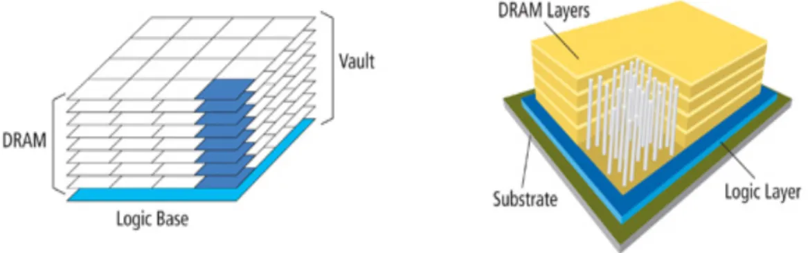
Recent technology have advances have made it possible to—through the use of through-silicon via (TSV) technology—integrated memory and logic vertically. Be-cause memory and logic are not directly mixed, the cost is not as high as putting compute in memory; density is also greatly improved. 3D-stacking does, however, al-low for very high bandwidths, and al-low latency, while also improving energy efficiency. Micron’s Hybrid Memory Cube (HMC) [73] and Tezzaron’s Octopus [82] are two such efforts that seems very promising. Figure 2.3 shows a high-level overview of Micron’s HMC technology. In this figure we can see that several layers of DRAM are connected to a logic layer using TSVs. This technology, e.g., can provide over 100GB/s of bandwidth at a fraction of the power of conventional DRAM [73].
Given the promise of 3D-stacked memory, there has been a renewed interest in processing-near-memory architectures—particularly for big data workloads which, given their small compute to data ratio, seem well-suited for 3D-stacked architec-tures. Many recent works have looked at using 3D-stacked memory in the context of big data workloads with promising results: [15, 29, 42, 43, 45, 75].
Given the promise of utilizing alternative memory and networking technologies, this dissertation argues that we will need to move away from commodity off-the-shelf
hardware to build our data centers. The benefits will be improved performance, better space utilization, and better energy efficiency.
CHAPTER III
Integrated 3D-Stacked Server Architectures
3.1
Background
3.1.1 Cloud Computing Design
Figure 3.1a shows the design of a standard web server setup. A load balancer typically has one or more virtual IP (VIP) addresses configured. Each domain is routed by a DNS to a particular load balancer, where requests are then forwarded to a free server. After the load balancer a fleet of front-end servers service the web request. If needed, these web servers will contact a back-end data store to retrieve custom content that pertains to the user, which means that all servers could connect to the back-end data store.
VIP www.ex.com Database Client Client Client Web Server Web Server Web Server Web Server Web Server
(a) The database handles all reads and writes. VIP www.ex.com Database Client Client Client Web Server Web Server Web Server Web Server Web Server
Key Value Store Caching Layer
(b) The database only handles writes and reads that miss in the cache.
In Figure 3.1b a caching layer is added, which can service any read request that hits in the cache. A request will first be forwarded to the caching layer on any read. If the requested data is present, the caching layer returns its copy to the client. If the data is not present, a query will be sent to the back-end data store. After the data returns, the server handling the request will issue a write to the caching layer along with the data. Future requests for that data can then be serviced by the caching layer. All write requests are sent directly to the back-end data store. Updating values in the caching layer depends on how it is configured. The two most common cases are that writes are duplicated to the caching layer or a time-to-live is placed on data in the caching layer.
3.1.2 Scaling in the Cloud
In general, the traffic to a website varies by the time of day and time of year. Data published by Netflix [71] demonstrates how traffic to their site varies over a three day period. As their data shows, traffic peaks during midday, and is at its lowest point around midnight. They also quantify the corresponding number of front-end servers needed to maintain equal load throughout the day, which tracks closely with the traffic. While this is easy to do for front-end servers, because they maintain little state, back-end data stores are not easily scaled up and down. Netflix overcomes this problem by the extensive use of caching, which is a cheaper solution than scaling back-end data stores.
While turning on and off servers helps save power, it does not help reduce space because the servers must still be physically present in order to meet peak demand. To cope with the physical demands of scaling, new data centers must be built when a given data center is either over its power budget, or out of space. A recent report states Google is spending 390 million USD to expand their Belgium data center [74]. Facebook also has plans to build a new 1.5 billion USD center in Iowa[64]. Because
of this high cost, it is critical to avoid scaling by means of simply building new data centers or increasing the size of existing ones. This paper focuses on increasing phys-ical density within a fixed power budget in order to reduce the data center footprint of key-value stores.
3.1.3 Memcached
In this paper we use Memcached 1.4 as our key-value store. We choose Memcached as our key-value store because of its widespread use in cloud computing. Memcached does not provide data persistence and servers do not need to communicate with each other, because of this it achieves linear scaling with respect to nodes. To date, the largest Memcached cluster with published data was Facebook’s, which contained over 800 servers and had 28TB of DRAM in 2008 [89].
The ubiquity of Memcached stems from the fact that it is easy to use, because of its simple set of verbs. Only three details about Memcached need to be understood: first, it is distributed, which means that not every key will be on every server. In fact, a key should only be on one server, which allows the cluster to cache a large amount of data because the cache is the aggregate size of all servers. Second, the cache does not fill itself. While this may seem intuitive, the software using Memcached needs to ensure that after a read from the database, the data is stored in the cache for later retrieval. Entering data in the cache uses a SET, and retrieving data from the cache uses a GET. Lastly, there are several options to denote when data expires from the cache. Data can either have a time-to-live, or be present in the cache indefinitely. A caveat to using Memcached is that data will be removed from your cache if a server goes down as Memcached does not have persistent storage.
3.1.3.1 Versions and Scaling
There are several versions of Memcached: the current stable release is 1.4, and 1.6 is under development. Version 1.6 aims to fix scaling issues caused by running Memcached with a large number of threads. A detailed analysis is presented in [86]. Prior research has shown that Memcached saturates neither the network bandwidth, nor the memory bandwidth [54], due to inefficiencies in the TCP/IP stack. In this work, we distribute the work of the TCP/IP stack among many small cores to provide greater aggregate bandwidth while increasing the storage density. This is possible because 3D stacking provides higher bandwidth and a faster memory interface.
3.2
Related Work
Prior work has focused on increasing the efficiency or performance with respect to the RPS of Memcached systems, rather than density. As previously mentioned, we believe that density should be studied as a first class design constraint due to the high cost of scaling out data centers.
3.2.1 Characterizing Cloud Workloads
Ferdman et al. have demonstrated the mismatch between cloud workloads and modern out-of-order cores [22, 24]. Through their detailed analysis of scale-out work-loads on modern cores, they discovered several important characteristics of these workloads: 1) Scale-out workloads suffer from high instruction cache miss rates, and large instruction caches and pre-fetchers, are inadequate; 2) instruction and memory-level parallelism are low, thus leaving the advanced out-of-order core underutilized; 3) the working set sizes exceed the capacity of the on-chip caches; 4) bandwidth utilization of scale-out workloads is low.
3.2.2 Efficient 3D-Stacked Servers
Prior work has shown that 3D stacking may be used for efficient server design. PicoServer [42] proposes using 3D stacking technology to design compact and effi-cient multi-core processors for use in tier 1 servers. The focus of the PicoServer is on energy efficiency—they show that by closely stacking low-power cores on top of DRAM they can remove complex cache hierarchies, and instead, add more low-power cores. The improved memory bandwidth and latency allow for adequate through-put and performance at a significant power savings. Nanostores [15] build on the PicoServer design and integrate Flash or Memristors into the stack. Both PicoServer and Nanostores could be used in a scale-out fashion to improve density, although this was not addressed in the work. This paper builds on their designs to address density, particularly in the context of Memcached.
More recently, Scale-Out Processors [59] were proposed as a processor for cloud computing workloads. The Scale-Out Processor design uses 3D stacked DRAM as a cache for external DRAM and implements a clever prefetching technique[36]. Our designs differ in that we only use the on-chip DRAM or Flash for storage with no external backing memory. This is possible because we share the Memcached data over several independent stacks in the same 1.5U box.
3.2.3 Non-Volatile Memory File Caching in Servers
In addition to Nanostores, several prior studies have proposed using non-volatile memory for energy-efficiency in servers [44, 46, 78]. They propose using non-volatile memory (NAND Flash and phase-change memory) for file caching in servers. The use of a programmable Flash memory controller, along with a sophisticated wear-leveling algorithm, allow for the effective use of non-volatile memory for file caching, while reducing idle power by an order of magnitude.
3.2.4 Super Dense Servers
Super Dense Servers [21] have been shown to provide greater performance and efficiency for CPU-bound electronic commerce workloads. However, for workloads that require a large amount of physical memory—such as Memcached—traditional servers provided a better solution. By utilizing state-of-the-art 3D-stacked memory technology, we overcome the limitation of Super Dense Servers by providing a very high level of memory density in our proposed server designs.
3.2.5 McDipper
Memcached has been used at Facebook for a wide range of applications, including MySQL look-aside buffers and photo serving. Using DRAM for these applications is relatively expensive, and for working sets that have very large footprints but moderate to low request rates, more efficient solutions are possible. Compared with DRAM, Flash solid-state drives provide up to 20× the capacity per server and still supports tens of thousands of operations per second. This prompted the creation of McDipper, a Flash-based cache server that is compatible with Memcached. McDipper has been in active use in production at Facebook for nearly a year to serve photos [25]. Our Iridium architecture targets these very large footprint workloads which have moderate to low request rates. We further extend their solution by using Toshiba’s emerging 16-layer pipe-shaped bit cost scalable (p-BiCS) NAND Flash [41], which allows for density increases on the order of 5× compared to 3D-DRAM.
3.2.6 Enhancing the Scalability of Memcached
Wiggins and Langston [86] propose changes in Memcached 1.6 to remove bottle-necks that hinder performance when running on many core systems. They find that the locking structure used to control access to the hash table and to maintain LRU
gate the lock contention they use fine grain locks instead of a global lock. In addition, they modify the replacement algorithm to use a pseudo LRU algorithm, which they call Bags. Their proposed changes increase the bandwidth to greater than 3.1 MRPS, which is over 6× higher than an unmodified Memcached implementation.
3.2.7 TSSP
Lim et al. propose TSSP [54], which is an SoC including a Memcached accelerator to overcome the need for a large core in Memcached clusters. They find that, due to the network stack, Intel Atom cores would not be able to replace Intel Xeons in a standard cluster configuration. TSSP is able to offload all GET requests from the processor to the accelerator. The offload is accomplished by having a hash table stored in hardware and having a smart NIC that is able to forward GET requests to the accelerator. After data for a key is found, the hardware generates a response. Because little work needs to be done by software, an ARM Cortex-A9 is a suitable processor. The TSSP architecture achieves 17.63 KRPS/Watt.
3.2.8 Resource Contention in Distributed Hash Tables
distributed hash table (DHT) can suffer from issues that arise because there is not a uniform distribution of requests across resources. Keys in a key value store are assigned a resource by mapping a key onto a point in a circle. From this circle each node is assigned a portion of the circle, or arc. A server is responsible to store all data for keys that map onto their arc. Prior work dealing with resource contention in DHTs shows that increasing the number of nodes in the DHT reduces the probability of resource contention, because each node is responsible for a smaller arc [40, 80]. Typically, increasing the number of nodes has been accomplished by assigning one physical node to several virtual nodes. These virtual nodes are then distributed around the circle, which results in a more uniform utilization of resources.
Because we increase the number of physical cores with Mercury and Iridium, resource contention should be minimized.
3.2.9 TILEPro64
Berezecki et al. [9] focus on adapting Memcached to run on the TILEPro64. In this work they cite power consumption of data centers as an important component for the success of a web service. With this in mind, they aim to improve the efficiency of Memcached by running it on a TILEPro64. They compare their implementation to both Opteron and Xeon processors running Memcached, and report an RPS/W of 5.75 KRPS/W, which is an improvement of 2.85× and 2.43× respectively.
3.2.10 FAWN
Andersen et al. design a new cluster architecture, called FAWN, for efficient, and massively parallel access to data [2]. They develop FAWN-KV—an implementation of their FAWN architecture for key-value stores that uses low-power embedded cores, a log-structured datastore, and Flash memory. With FAWN-KV they improve the efficiency of queries by two orders of magnitude over traditional disk-based systems. The FAWN system focuses on the key-value and filesystem design, whereas our work focuses on designing very dense servers.
3.3
Mercury and Iridium
The Mercury and Iridium architectures are constructed by stacking ARM Cortex-A7s, a 10GbE NIC, and either 4GB of DRAM or 19.8GB of Flash into a single 3D stack. The MAC unit of the NIC, which is located on the 3D stack, is capable of routing requests to the A7 cores. A conceptual representation is presented in Figure 3.2a. To evaluate the use of 3D stacks with key-value stores, we vary the number
21 mm 21 mm 21 mm 18 mm Me rcu ry 9-Laye rs 279 mm2 15.5 mm 1.5U Motherboard 1,089 cm2 21 mm 13 in 13 in 10GbE PHY x2 441 mm2 400-Pin BGA Package Mercury 441 mm2 400-Pin BGA Package Pa cka ged 2.6 in 19 in 13 .5 mm 16 mm 1.5U Serv er
(a) 1.5U server with 96 Mercury stacks NIC (MA C+B uffe rs) A7s A7s D R A M L o g i c DRAM
(b) The 3D-stacked Mercury archi-tecture
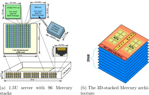
Figure 3.2: A Mercury server and a single stack. A Mercury stack is made up of 8 DRAM layers, each 15.5mm×18mm, stacked with a logic layer containing the processing elements, DRAM peripheral logic, and NIC MAC & buffers. These stacks are then placed in a 400-pin BGA package. The 1.5U enclosure is limited to 96 Ethernet ports, each of which will be connected to a Mercury stack. Therefore, 96 Mercury stacks and 48 Dual NIC PHY chips are placed in the 1.5U enclosure. Due to space limitations a separate diagram of Iridium is omitted, however the high-level design is similar—the only difference being that we use a single layer of 3D-stacked Flash for the Iridium design.
configuration. We designate the different architectures as Mercury-n or Iridium-n, where n is the number of cores per stack. We estimate power and area requirements based off of the components listed in table 3.1.
3.3.1 Mercury
While the primary goal of Mercury and Iridium is to increase data storage density, this cannot be done at the expense of latency and bandwidth—the architecture would not be able to meet the service-level agreement (SLA) requirements that are typical of Memcached clusters. Thus we utilize low-power, in-order ARM Cortex-A7 cores in our 3D-stacked architecture, and as we will show in §3.5, we are able to service a majority of requests within the sub-millisecond range.
3.3.1.1 3D Stack
The proposed Mercury architecture relies on devices from Tezzeron’s 3D-stacking process [81]. This process allows us to stack 8 memory layers on a logic die through finely-spaced (1.75µm pitch), low-power TSVs. The TSVs have a feedthrough capac-itance of 2-3fF and a series resistance of < 3Ω. This allows as much as 4GB of data in each individual stack.
The 4GB stack’s logical organization is shown in Figure 3.3a. Each 4GB 3D chip consists of eight 512MB DRAM memory dies stacked on top of a logic die. The orga-nization of the DRAM die is an extension [27] of Tezzaron’s existing Octopus DRAM solution [82]. Each 3D stack has 16 128-bit data ports, with each port accessing an independent 256MB address space. Each address space is further subdivided into eight 32MB banks. Each bank, in turn, is physically organized as a 64×64 matrix of subarrays. Each subarray is a 256×256 arrangement of bit cells, and is 60µm×35µm. Figure 3.3b shows the physical floor plan of each DRAM memory die and the logic die. The logic die is fabricated in a 28nm CMOS process and consists of address-decoding logic, global word line drivers, sense amplifiers, row buffers, error correction logic, and low-swing I/O logic with pads. Each memory die is partitioned into 16 ports with each port serving 1 of the 16 banks on a die. The memory die is fabricated in a 50nm DRAM process and consists of the DRAM subarrays along with some logic, such as local wordline drivers and pass-gate multiplexers.
While there are more advanced DRAM processes (e.g. 20nm), TSV yield in ex-isting 3D-stacked prototypes has only been proven up to the 50nm DRAM process node [47, 73]. All subarrays in a vertical stack share the same row buffer using TSVs, and at most one row of subarrays in a vertical stack can have its contents in the row buffer, which corresponds to a physical page. Assuming an 8kb page, a maximum of 2,048 pages can be simultaneously open per stack (128 8kb pages per bank × 16
Component Power (mW) Area (mm2)
A7@1GHz 100 0.58
A15@1GHz 600 2.82
[email protected] 1,000 2.82
3D DRAM (4GB) 210 (per GB/s) 279.00
3D NAND Flash (19.8GB) 6 (per GB/s) 279.00
3D Stack NIC (MAC) 120 0.43
Physical NIC (PHY) 300 220.00
Table 3.1: Power and area for the components of a 3D stack.
DRAM BW (GB/s) Capacity
DDR3-1333 [73] 10.7 2GB
DDR4-2667 [73] 21.3 2GB
LPDDR3 (30nm) [5] 6.4 512MB
HMC I (3D-Stack) [73] 128.0 512MB
Wide I/O (3D-stack, 50nm) [47] 12.8 512MB Tezzaron Octopus (3D-Stack)[82] 50.0 512MB Future Tezzaron (3D-stack)[27] 100.0 4GB Table 3.2: Comparison of 3D-stacked DRAM to DIMM packages.
Subarray 256x256 bits Information bits (256x256)b x 64x64 = 256Mb 64 Horizontal 6 4 V e r t i c a l 63,0 2,0 1,0 0,0 63,1 2,1 1,1 0,1 63,63 2,63 1,63 0,63 Port 0 256Mb x 8 = 2Gb Port 15 256Mb x 8 = 2Gb 3D Memory Layer #2 (4Gb) Bank 1 3D Memory Layer #1 (4Gb) Bank 0 Bank 0 Bank 1 3D Memory Layer #8 (4Gb) Bank 7 Bank 7 3D Logic Layer Peripheral Logic Peripheral Logic TSVs
(a) Logical organization of the 4GB 3D-stacked DRAM. Por t 0 Po rt 0 Po rt 1 Po rt 2 Po rt 3 Po rt 4 Po rt 5 Po rt 6 Po rt 7 Po rt 8 Po rt 9 Po rt 10 Po rt 11 Po rt 12 Po rt 13 Po rt 14 Po rt 15 Pe ri ph er al L og ic Pe ri ph er al L og ic Pe ri ph er al L og ic Pe ri ph er al L og ic One of the 8 4Gb Memory Dies in the Stack Logic Die 256Mb Bank Each port serves 1 Bank on a Memory Die Decode + sensing + other logic 18 m m 15.5mm
(b) Physical floor plan of the logical die and a 512MB memory die in the 3D stack. The top-down view of the stack shows that DRAM banks are arranged around spines of periph-eral logic.
Figure 3.3: Logical organization and physical floorplan of the 3D DRAM.
banks per physical layer). The device provides a sustained bandwidth of 6.25GB/s per port (100GB/s total).
3.3.1.2 Address Space
The 3D stack DRAM has 16 ports for memory access, this segments the 4GB stack into 256MB chunks. Each core is allocated one or more ports for memory access, which prevents Memcached processes from overwriting each other’s address range. If the Mercury or Iridium architectures increase past 16 cores, additional ports would need to be added, or cores would need to share ports.
3.3.1.3 Memory Access
Other studies have shown that small cores alone are not able to provide the needed bandwidth to be useful in key-value stores [54]. Mercury differs from this research
lower latency through 3D integration. For comparison, Table 3.2 shows the bandwidth and capacity of several current and emerging memory technologies. Coupling cores on the 3D stack allows Mercury to forego using an L2 cache, which prior research has shown to be inefficient [54], and issue requests directly to memory. The 3D DRAM has a closed page latency of 11 cycles at 1GHz. By having a faster connection to memory we mitigate the cache thrashing by the networking stack reported in [54].
3.3.1.4 Request Routing
To simplify design and save power we do not use a router at the server level. Instead, the physical network port is tied directly to a 3D stack. This allows for each stack to act as a single node, or multiple nodes, without having contention from other stacks. At the stack, we base our design off of the integrated NIC on the Niagra-2 chip [7, 51]. The integrated NIC is capable of buffering a packet and then forwarding it to the correct core. Cores on the same stack will need to run Memcached on different TCP/IP ports. This simplifies request routing on the stack. The physical (PHY) portion of the 10GbE is based on the Broadcom design [12] and is not located on the stack.
3.3.2 Iridium
Due to the high cost of server real estate, physical density is first-class design con-straint for key-value stores. Facebook has developed McDipper [25], which utilizes Flash memory to service low-request-rate transactions while improving density by up to 20×. McDipper has been in use for over a year to service photos at Facebook. With Iridium we target these low-request-rate applications and explore the tradeoff between physical density and throughput by replacing the DRAM in a Mercury stack with NAND Flash memory. This comes at the expense of throughput per GB of
storage, but is still applicable to low-request-rate high-density Memcached clusters, such as Facebook’s photo server.
3.3.2.1 3D Stacked Flash
McDipper reported an increase in density by 20× when moving from DRAM DIMMs to Solid-State drives. Because the Mercury design already improved density through 3D-DRAM we will not see as significant a gain. To quantify the improve-ment in the density of the stack we estimate our Flash density using the cell sizes of Toshiba’s emerging pipe-shaped bit cost scalable (p-BiCS) NAND Flash [41]. Flash cells are smaller than DRAM cells, offering a 2.5×increase in density. Because p-BiCS has 16 layers of 3D Flash1, as opposed to 8 layers for 3D-stacked DRAM, this leads to an overall 4.9×increase in density for Iridium stacks. For our access organization we maintain Mercury’s 16 separate ports to DRAM by including 16 independent Flash controllers. The read/write latency values and energy numbers used for simulation are drawn from [28], which are conservative for 3D-stacked Flash. The power and area numbers for Flash are shown in table 3.1. In addition, because the Flash latency is much longer, an L2 cache is needed to hold the entire instruction footprint. Our results in §3.5.2 will confirm this assumption.
3.4
Methodology
The following sections describe our Memcached setup, as well as our simulation framework and power models.
1The 16 Flash layers are contained in a single monolithic layer of 3D Flash, and are not 3D
1.5U Mercury Server 1.5U Iridium Server
Cores per Stack 1 2 4 8 16 32 1 2 4 8 16 32
A15 1.5GHz Area(cm2) 635 635 576 331 179 86 635 635 635 363 185 93 Power(W) 449 569 749 750 750 720 328 449 690 740 737 730 Density(GB) 384 384 348 200 108 52 1,901 1,901 1,901 1,089 554 277 Max BW(GB/s) 27 55 99 114 123 118 1 3 6 7 7 7 A15 1GHz Area(cm2) 635 635 635 496 278 139 635 635 635 595 304 152 Power(W) 401 473 618 745 742 728 281 353 498 750 740 728 Density(GB) 384 384 384 300 168 84 1,901 1,901 1,901 1,782 911 455 Max BW(GB/s) 27 54 108 169 189 189 2 3 6 11 11 11 A7 1GHz Area(cm2) 635 635 635 635 635 616 635 635 635 635 635 635 Power(W) 341 353 378 429 529 749 221 233 258 309 410 612 Density(GB) 384 384 384 384 384 371 1,901 1,901 1,901 1,901 1,901 1,901 Max BW(GB/s) 19 37 75 149 299 578 1 3 6 12 22 44
Table 3.3: Power and area comparison for 1.5U maximum configurations. For each configuration we utilize the maximum number of stacks we can fit into a 1.5U server, which is 96, or until we reach our power budget of 750W. The power and bandwidth numbers are the maximum values we observed when servicing requests from 64B up to 1MB.
3.4.1 Memcached
For our experiments we utilize the latest stable version of Memcached cross-compiled for the ARM ISA. We modify our simulation infrastructure, which will be described in the next section, to collect timing information. We do this, as opposed to using library timing functions such asgettimeofday(), because they do not perturb the system under test. All experiments are run with a single Memcached thread.
For our client we use an in-house Java client that is based on the work by Whalin [85]. Because we measure performance from the server-side, the overhead of running Java is not included with the measurements.
3.4.2 Simulation Infrastructure
To calculate the request rates that Mercury and Iridium are able to achieve, we used the gem5 full-system simulator [10]. With gem5, we are able to model multiple networked systems with a full operating system, TCP/IP stack, and Ethernet devices. We use Ubuntu 11.04 along with version 2.6.38.8 of the Linux kernel for both the server and client systems. On the client side we useJava SE 1.7.0 04-ea.
While Mercury and Iridium both utilize ARM Cortex-A7 cores, we also explore the possibility of using the more aggressive, out-of-order Cortex-A15 core by modelling both cores in our simulation infrastructure. Simulations use a memory model with a memory latency varied from 10-100ns for DRAM and 10-20µs for Flash Reads. Our memory model represents a worst-case estimate as it assumes a closed-page latency for all requests. To measure the TPS we vary request size from 64B to 1MB, doubling request size at each iteration. We do not consider values greater than 1MB for the following reasons: 1) Memcached workloads tend to favor smaller size data; 2) prior work [54, 86, 4], against which we compare, present bandwidth per watt at data sizes of 64B and 128B; and, 3) requests that are 64KB or larger have to be split up into multiple TCP packets.
3.4.3 TPS calculation
To calculate the TPS we collect the RTT for a request, i.e., the total time it takes for a request to go from the client to the server, then back to the client. Because we use only a single thread for Memcached, the TPS is equal to the inverse of the RTT. The RTT for each request is obtained by dumping TCP/IP packet information from gem5’s Ethernet device models. The packet trace is run through TShark [88] to parse out timing information. After timing information is obtained from gem5 for a single core, we apply linear scaling to calculate TPS at the stack and server level. Linear scaling is a reasonable approach in this context because each core on a stack is running a separate instance of Memcached. Running separate instances avoids the contention issue raised by the work of Wiggins and Langston[86]. For the Mercury-32 and Iridium-32 configurations we use the same approach, however we assume two cores per memory port (as mentioned previously we can fit a maximum of 16 memory ports on a stack), because Memcached has been shown to scale well for two threads [86].
3.4.4 Power Modeling
Table 3.1 has a breakdown of power per component, and Table 3.3 has the cumu-lative power totals for each configuration of Mercury and Iridium at their maximum sustainable bandwidths. To calculate the power of an individual stack we add to-gether the power of the NIC, cores, and memory. The integrated 10GbE NIC is comprised of a MAC and buffers. The MAC power estimates come from the Niagra-2 design [7, 51], and the buffers are estimated from CACTI [68]. The ARM Cortex-A7 and Cortex-A15 power numbers are drawn from [30], and the 3D DRAM is calculated from a technical specification obtained from Tezzaron [27]. Because DRAM active power depends on the memory bandwidth being used, we must calculate the stack power for the maximum bandwidth that a given number of cores can produce. Similar calculations are used to obtain NAND Flash power, which use read and write energy values drawn from [28]. Finally, each stack requires an off-stack physical Ethernet port. Power numbers for the PHY are based on a Broadcom part [12].
3.4.4.1 Power Budget for 1.5U Mercury System
In calculating the power for the 1.5U server system we multiply the per stack power by the number of stacks. To determine how many stacks can fit in a 1.5U power budget, we start with a 750W power supply from HP [32]. First 160W is allotted for other components (disk, motherboard, etc.), after this we assume a conservative 20% margin for miscellaneous power and delivery losses in the server. This results in a maximum power of (750−160)×0.8 = 472W for Mercury or Iridium components.
3.4.4.2 TPS/Watt calculation
When calculating the maximum number of 3D stacks that fit in a system, we used the maximum memory bandwidth that Mercury and Iridium can produce. How-ever, for proper TPS/Watt calculation, we estimate power by using the GB/s power consumption of DRAM and Flash at the request size we are testing.
3.4.5 Area
Area estimates for the 10GbE NIC were obtained by scaling the Niagra-2 MAC to 28nm and the buffers were obtained from CACTI. The area for an ARM Cortex-A7 chip in 28nm technology is taken from [30]. DRAM design estimates for the next generation Tezzaron Octopus DRAM were obtained from Tezzaron [27]. Given the available area on the logic die of the Tezzaron 3D-stack, we are able to fit >400 cores on a stack. However, the memory interface becomes saturated if there are ≥64 cores in a stack. We are further limited, by the number of DRAM ports in a stack, to 16 cores per stack unless cores share the memory controller. In each 1.5U server, multiple 3D stacks are used to increase the bandwidth and density. Once packaged into a 400-pin 21mm×21mm ball grid array (BGA) package, each stack consumes 441mm2. Each NIC PHY chip is also 441mm2 and contains 2 10GbE PHYs/chip. If
77% of a 1.5U, 13in×13in motherboard [52] is used for Mercury or Iridium stacks and associated PHYs, t