MAITLAND BOULEVARD (EB)
OVER I-4
I-4
I-4
I-4
MAITLAND BOULEVARD
MAITLAND BOULEVARD
I-4
I-4
I-4
C H A P TE R 6 Chapter 6Interstate 4 Interchange at Maitland Boulevard
Bridge Development Report – Eastbound Maitland Boulevard over I-4 Chapter 6
ES-1
EXECUTIVE SUMMARY – CHAPTER 6
This Bridge Development Report was prepared to document the decision process and recommendations for constructing a bridge carrying Maitland Boulevard (eastbound) over I-4 as part of the I-4/Maitland Boulevard interchange improvement project. This bridge is a two-span curved structure with spans of 164 feet 5 inches and 158 feet 7 inches. The pier and end bents are skewed to match the I-4 alignment.
The structure types evaluated for suitability at this site were Florida Bulb-T (FBT) 72 spliced girders, cast-in-place (CIP) concrete box girders, steel plate girders, and steel box girders. Criteria used to evaluate the alternatives include construction cost, traffic control, constructability, and aesthetics.
The recommended superstructure is the FBT 72 spliced girder alternative due to its competitive cost, ease of construction, and reduced MOT requirements. The recommended intermediate pier alternative is single columns founded on 24-inch pre-stressed concrete pile footers. The recommended end bent is rectangular concrete caps founded on 24-inch square prestressed concrete piles. Permanent proprietary walls are recommended at the bridge abutments.
The total estimated construction cost of the bridge is $3,916,000 including aesthetic
Interstate 4 Interchange at Maitland Boulevard i Bridge Development Report – Eastbound Maitland Boulevard over I-4
Chapter 6
TABLE OF CONTENTS
EXECUTIVE SUMMARY – CHAPTER 6 --- ES-1 1.0 INTRODUCTION ---1-1
1.1 Location---1-1
1.2 Existing Roadway Conditions ---1-1
1.3 Existing Structure ---1-1
1.4 Geotechnical Conditions/Environmental Classification---1-1
1.5 Utilities ---1-4
2.0 SUPERSTRUCTURE ---2-1
2.1 Bridge Layout ---2-1
2.2 Superstructure Alternatives---2-1
2.2.1 Alternative 1 – Florida Bulb-T 72 Spliced Girders ---2-5
2.2.2 Alternative 2 – CIP Concrete Box Girder---2-5
2.2.3 Alternative 3 – Steel Plate Girders---2-7
2.2.4 Alternative 4 – Steel Box Girders ---2-7
2.3 Miscellaneous Superstructure Details --- 2-10
2.3.1 Expansion Joints --- 2-10 2.3.2 Bearings --- 2-10 2.3.3 Deck Drainage --- 2-12 3.0 SUBSTRUCTURE ---3-1 3.1 Columns ---3-1 3.2 Geotechnical ---3-1
3.2.1 18-inch, 24-inch, and 30-inch Prestressed Concrete Piles ---3-2
3.2.2 Steel H-piles ---3-2
3.2.3 Steel Pipe Piles---3-2
3.3 Pile Evaluation ---3-2
3.4 End Bents ---3-6
3.5 Footings ---3-6
3.6 Piers ---3-6
Interstate 4 Interchange at Maitland Boulevard ii Bridge Development Report – Eastbound Maitland Boulevard over I-4
Chapter 6
3.6.2 CIP Concrete Box Girder Alternative---3-6
3.7 Foundation Constructability ---3-7
4.0 COST ESTIMATE---4-1
4.1 Unit Costs (BDR Cost Estimating Guidelines) ---4-1
4.2 Other Costs ---4-1
4.3 Cost Summary ---4-1
5.0 TRAFFIC CONTROL ---5-1
5.1 Foundation Construction ---5-1
5.2 FBT 72 Spliced Girder Alternative ---5-1
5.3 CIP Concrete Box Superstructure Construction---5-3
5.4 Steel Superstructure Construction---5-3
6.0 CONSTRUCTABILITY ---6-1
6.1 Foundations ---6-1
6.2 Superstructure ---6-1
6.2.1 Florida Bulb-T 72 Spliced Girders ---6-1
6.2.2 CIP Concrete Box Girders ---6-1
6.2.3 Steel Girder Alternatives ---6-1
7.0 AESTHETICS ---7-1 8.0 EVALUATIONS ---8-1 8.1 Cost---8-1 8.2 Traffic Control ---8-1 8.3 Constructability ---8-2 8.4 Aesthetics ---8-2 8.5 Recommendation ---8-2
Interstate 4 Interchange at Maitland Boulevard iii Bridge Development Report – Eastbound Maitland Boulevard over I-4
Chapter 6
LIST OF FIGURES
Figure 1-1 Bridge Location at I-4 Maitland Blvd. Interchange ---1-2 Figure 1-2 Project Photographs ---1-3 Figure 2-1 Plan and Elevation (1 of 3) Maitland Blvd. Over I-4---2-2 Figure 2-2 Plan and Elevation (2 of 3) Maitland Blvd. Over I-4---2-3 Figure 2-3 Plan and Elevation (3 of 3) Maitland Blvd. Over I-4---2-4 Figure 2-4 FBT 72 Spliced Girder Alternative Typical Section ---2-6 Figure 2-5 CIP Concrete Box Girder Alternative Typical Section ---2-8 Figure 2-6 Steel Plate Girder Alternative Typical Section ---2-9 Figure 2-7 Steel Box Girder Alternative Typical Section ---2-11 Figure 3-1 24” Square Prestressed Concrete Pile Foundation – FBT 72 Spliced Girder and Steel Girder Alternatives ---3-4 Figure 3-2 24” Square Prestressed Concrete Pile Foundation – CIP Concrete Box Girder Alternative---3-5 Figure 5-1 Foundation Construction – Pier 2 ---5-2 Figure 6-1 FBT 72 Spliced Girder Alternative Eastbound - Construction Sequence---6-2 Figure 6-2 CIP Concrete Box Girder Alternative - Temporary Falsework ---6-3 Figure 7-1 Bridge Aesthetics – FBT 72 Spliced Girder Alternative ---7-2 Figure 7-2 Bridge Aesthetics – CIP Concrete Box Girder Alternative ---7-3 Figure 7-3 Bridge Aesthetics – Steel Plate Girder Alternative ---7-4 Figure 7-4 Bridge Aesthetics – Steel Box Girder Alternative---7-5 Figure 7-5 Bridge Aesthetic Photos ---7-6 Figure 7-6 Bridge Aesthetic Photos ---7-7 Figure 7-7 Fiberglass Panel Rendering ---7-8
LIST OF TABLES
Table 3-1 Alternative Foundation Types ---3-1 Table 3-2 Substructure Cost Comparison (Spliced Girder Alternative)---3-3 Table 4-1 Estimated Construction Cost for Eastbound Maitland Boulevard over I-4 ---4-2 Table 8-1 Alternative Evaluation Matrix ---8-1
INTRODUCTION
I-4
I-4
I-4
MAITLAND BOULEVARD
MAITLAND BOULEVARD
I-4
I-4
I-4
Interstate 4 Interchange at Maitland Boulevard 1-1 Bridge Development Report – Eastbound Maitland Boulevard over I-4
Chapter 6
1.0 INTRODUCTION
1.1 Location
Maitland Boulevard will be reconstructed between Keller Road and Sandspur Road. Improvements include 12-foot shoulders and added lanes to ease traffic movements at the I-4/Maitland Boulevard interchange. Currently, Maitland Boulevard passes over four westbound lanes of 4, three eastbound lanes of 4, and a single-lane ramp that exits I-4 eastbound. A large submerged drainage area between the ramp and I-I-4 eastbound is also spanned by this bridge. The project location map is shown in Figure 1-1.
1.2 Existing
Roadway
Conditions
Within the project area, Maitland Boulevard is classified as an urban minor arterial and is currently a six-lane divided roadway.
The existing eastbound Maitland Boulevard bridge typical section has three 12-foot travel lanes flanked by a 6-foot inside shoulder and a 10-foot outside shoulder. Standard 1-foot 6½-inch traffic barriers border the travel way.
I-4 is classified as an urban freeway/expressway. I-4 eastbound has three through lanes, and I-4 westbound has three through lanes and one lane for an entrance ramp.
1.3 Existing
Structure
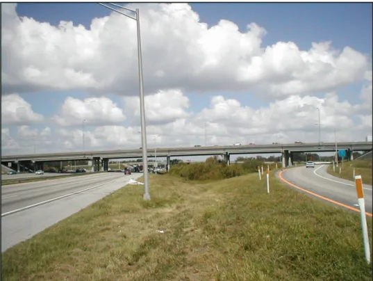
The existing eastbound bridge has seven simple spans. The bridge number for the existing bridge is 750290. The span arrangement is 36 feet, 115 feet 6 inches, 106 feet, 79 feet 6 inches, 79 feet 6 inches, 84 feet and 33 feet 9 inches with a constant 55-foot 1-inch bridge width. The superstructure consists of a 7-1-inch cast-in-place concrete deck supported on AASHTO Type II and IV prestressed concrete beams. The substructure consists of intermediate piers with rectangular pier caps supported by three 3-foot diameter columns. Each column is founded on a rectangular pile cap, supported by four to eight 18-inch square concrete batter piles. End bents consist of rectangular caps supported on 18-inch square concrete batter piles. A sloped paved embankment was placed in front of each end bent. See Figure 1-2 for general project photos.
1.4
Geotechnical Conditions/Environmental Classification
Geotechnical and Environmental Consultants, Inc. prepared the preliminary geotechnical report for Eastbound Maitland Boulevard over I-4.
A summary of the subsurface conditions from the land borings is as follows:
• +90 to +65 feet NAVD: Loose to medium dense fine sane with varying silt content
L a k e D e st in y D r. L a k e D e st in y D r. F u tu re L R T C o rr id o r (s c h e m a tic ) L D L D. MAIT AN BV Hope Rd. W y m o re R d . 4 IN T E R S TA TE Sandspur Rd. 4 IN T E R S T A T E W y or e R d . m P e d e st ri a n B ri d g e N T S
4
M ai tla nd B lv dSR 400 (I-4) ORANGE AND SEMINOLE COUNTIES Fin No. 242484-6-32-01
Figure 1-1
North of K
ennedy Boulevard
to north of Maitland Boulevard
Maitland Blvd. (EB) over I-4
4
Maitland Blvd
SR 400 (I-4) Fin No. 242484-6-32-01
ORANGE AND SEMINOLE COUNTIES
Figure 1-2
North of Kennedy Boulevard to north of Maitland Boulevard
Eastbound Maitland Blvd. over I-4 - Elevation View looking North
Eastbound Maitland Blvd. over I-4 - Looking East near Pier 2
Interstate 4 Interchange at Maitland Boulevard 1-4 Bridge Development Report – Eastbound Maitland Boulevard over I-4
Chapter 6
• +65 to +38 feet NAVD: Very loose to loose to fine sand with varying silt content
(SP-SM, SM).
• +38 to +22 feet NAVD: Medium dense silty fine sand (SM) and stiff to very stiff
elastic silt with sand to silt (ML, MH), fat clay with sand to fat clay (CH).
• +22 to -15 feet NAVD: Dense to very dense silty fine sand (SM), hard sandy silty
to silt with sand (ML) and limestone.
The substructure has an environmental classification of slightly aggressive for all elements. The superstructure has also been classified as slightly aggressive.
1.5 Utilities
SUPERSTRUCTURE
I-4
I-4
I-4
MAITLAND BOULEVARD
MAITLAND BOULEVARD
I-4
I-4
I-4
Interstate 4 Interchange at Maitland Boulevard 2-1 Bridge Development Report – Eastbound Maitland Boulevard over I-4
Chapter 6
2.0 SUPERSTRUCTURE
2.1 Bridge
Layout
The proposed eastbound bridge will be constructed approximately 50 feet north of its current location. The new structure will be a two-span continuous bridge with an approximate length of 323 feet along the baseline of eastbound Maitland Boulevard. The span arrangement will be 164 feet 5 inches and 158 feet 7 inches. The bridge has a constant roadway width of 87 feet 1 inch.
The bridge will carry five lanes of traffic with 12-foot shoulders on each side. All lanes and shoulders of I-4, Ramp B, and Ramp D1 will be spanned by the proposed structure. It is necessary to place Pier 2 in the median of the Ultimate I-4. The District has given a directive that the Special Use Lanes (SUL) and General Use Lanes (GUL) of I-4 in each direction shall be contiguous with 12-foot wide full depth shoulders. This will allow flexibility in the Ultimate I-4 Section to go from three GUL, two 12-foot shoulders, and two SUL to a seven GUL Section. This directive essentially rules out locating any substructure units between the SUL and GUL. Spans 1 and 2 will each carry traffic over three 12-foot GUL, two 12-foot shoulders, and two 12-foot wide SULs.
The depth of the superstructure is limited by the unique vertical geometry of the Maitland Boulevard/I-4 interchange. Both eastbound and westbound Maitland Boulevard profiles are restricted by vertical clearances related to the Ramp C1 and Ramp A1 underpasses (separate structures) as well as the I-4 travel lanes. Ramp B and Ramp D1, which pass under the Maitland Boulevard over I-4 Bridge, do not control the Maitland Boulevard profile. The maximum superstructure depth given these constraints is approximately 7 feet 4 inches. The point of minimum vertical clearance is on the inside edge of eastbound SUL. This depth provides the necessary vertical clearance of 16 feet 6 inches for all travel lanes.
Standard bridge traffic barriers will be used on both sides of the bridge. Proprietary walls will be needed at the beginning and end of the bridge to maintain the fill for the grade separation. See Figure 2-1, Figure 2-2 and Figure 2-3 for the plan and elevation of the proposed bridge.
2.2 Superstructure
Alternatives
An effective superstructure balances both span limitation of beams and beam spacing. However, structure depth limits can often control and limit some superstructure options. Four superstructure alternatives will be efficient for the maximum 164-foot-5 inch span length and will have structure depth of less than 7 feet 4 inches.
• Florida Bulb-T 72 Spliced Girder
• Cast-in-Place Concrete Box Girder
• Steel Plate Girder
Interstate 4 Interchange at Maitland Boulevard 2-5 Bridge Development Report – Eastbound Maitland Boulevard over I-4
Chapter 6
2.2.1
Alternative 1 – Florida Bulb-T 72 Spliced Girders
Spliced concrete girders with main spans in excess of 220 feet have been successfully used on many bridges in Florida. The required span lengths are well within the capabilities of this type of superstructure. Cost savings is the primary advantage of using post-tensioned Florida Bulb-T (FBT) 72 spliced girders.
The main span unit will consist of nine precast, prestressed FBT 72 girders made continuous through the use of post-tensioning tendons anchored and stressed at both ends of the unit with an 8½-inch cast-in-place concrete deck. Precast segments over the piers will have an approximate length of 59 feet. The flanking span segments will have approximate lengths of 134 feet and 128 feet accordingly. 1-foot closure pours will be cast-in-place during construction at the interface of the precast sections. Cantilevered sections at the interior pier will be supported on temporary supports (falsework) located in Span 1. This falsework will be located on one side of the pier section away from the existing travel lanes for support until the other segments are constructed.
The preliminary design documentation for the FBT 72 spliced girder alternative is included in Appendix C and a typical section is shown in Figure 2-4.
Initially, an alternative with two simple spans using FBT 78 was also considered. However, it would have resulted in span lengths up to 164 feet 6 inches (±). At these span lengths the limit of allowable prestress is reached. Also, transport of concrete beams this long is a major undertaking. Because of these reasons, FDOT District 5 has advised against recommending the FBT 78 for simple spans of similar length in the recent past.
2.2.2
Alternative 2 – CIP Concrete Box Girder
A cast-in-place (CIP) concrete box girder can be utilized to create an efficient superstructure that meets the span length and curvature requirements of the new structure. Aesthetics is the primary advantage of a cast-in-place superstructure. A major disadvantage of CIP construction is the high cost of formwork and falsework. Additional consideration is also given to maintenance of traffic because of the need for formwork and falsework over existing lanes of traffic.
A constant depth CIP concrete box girder alternative was developed as a viable alternative for the eastbound Maitland Boulevard over I-4 bridge given the span lengths and the needed structure depth. Since the eastbound and westbound Maitland Boulevard bridge over I-4 will be constructed in phases, opportunities exist for the reuse of formwork and falsework. The westbound structure will have the same depth and cross section as the majority of the eastbound bridge. See Chapter 7 for the similar typical sections of Westbound Maitland Boulevard over I-4. A comprehensive effort was made to estimate the costs associated with the construction of this alternative beyond a more expensive unit cost of concrete. Temporary substructure elements for support piers were included in the estimated costs for this alternative. These piers are needed for the falsework that support the formwork over I-4 traffic.
Interstate 4 Interchange at Maitland Boulevard 2-7 Bridge Development Report – Eastbound Maitland Boulevard over I-4
Chapter 6
The primary features of the CIP concrete box girder alternative are summarized below:
• Constant depth box
• Similar cross section for both Maitland Boulevard bridges over I-4
The preliminary design documentation for the CIP Concrete Box girder alternative is included in Appendix C and a typical section is shown in Figure 2-5.
Recently, the long-term performance of post-tensioned bridges has been called into question due to corrosion problems. It has been recognized that the procedures, specifications, materials, and inspection of the grouting operation have been insufficient. The FDOT has been proactive in both the identification of the problems and the development of solutions associated with post-tensioning systems. Due to the inland location of the Maitland Boulevard bridges, the changes to the Structures Design Guidelines, and grouting specifications, the long-term performance of the post-tensioning system should be consistent with the performance of the other superstructure alternatives examined in this report.
2.2.3
Alternative 3 – Steel Plate Girders
Curved steel plate girders can be readily designed and constructed to meet the requirements of the new structures. The cross section of the bridge allows a beam spacing of 11 feet 3 inches. Exterior deck cantilevers are only 4 feet 2 inches to reduce the load on the exterior girder. Flange thickness is varied to optimize the girder section throughout its length. The plate girder alternative utilizes eight girders with an 8½-inch cast-in-place concrete deck. Girders will utilize Grade 50 structural steel in all regions with A36 steel used for the cross-bracing. The girders will be horizontally curved.
The web depth of 70 inches (5 feet 10 inches) provides a maximum span to web depth ratio of 28.1. Maximum flange plate sizes were 22 inches x 1 3/8 inches over Pier 2. The preliminary design documentation for the plate girder alternative is included in Appendix C and a typical section is shown in Figure 2-6.
2.2.4
Alternative 4 – Steel Box Girders
Steel box girders offer improved aesthetics over the plate girders. The principal disadvantages of steel box girders are the increased complexity of detailing and fabrication. The FDOT BDR Cost Estimating Guidelines recommend increasing the cost for structural steel by approximately 20 percent for steel box girders.
The typical section for the Maitland Boulevard over I-4 bridges is ideal for steel box girders. Since both steel alternatives have eight webs, a superstructure section utilizing four box girders results in an efficient structure similar in steel quantity to the plate girder alternative.
Interstate 4 Interchange at Maitland Boulevard 2-10 Bridge Development Report – Eastbound Maitland Boulevard over I-4
Chapter 6
Improved aesthetics is the most important attribute of the steel box girders. The continuous lines of the bottom soffit will accentuate the slight curvature of the bridge alignment. FDOT-District 5 has generally recommended using box girders for curved structures in locations that call for higher aesthetic standards.
On a similar project (I-4/SR 408 Interchange), the District and the City of Orlando/Orange County Aesthetics Committee agreed on using steel box girders superstructure for all curved bridges over I-4.
The steel box girder alternative utilizes four boxes with an 8½-inch cast-in-place concrete deck. Boxes will utilize Grade 50 structural steel in all regions with A36 steel used for the internal-bracing, end diaphragms and pier diaphragms.
The ideal web depth is 72 inches (6 feet) that provides a maximum span to web depth ratio of 27.4 creating a slender attractive superstructure. Maximum flange plate sizes were 94 inches x 7/8 inches over the interior pier. The thickest top flange of 18 inches x 2¼ inches is also at this location. The preliminary design documentation for the plate girder alternative is included in Appendix C. The superstructure cross section developed for the steel box girder alternative is shown in Figure 2-7.
2.3 Miscellaneous
Superstructure
Details
2.3.1 Expansion
Joints
Due to the insignificant curvature of the superstructure, the movement of the superstructure will be along girder lines. Expansion joints will only be provided at the end bents to reduce maintenance and construction costs.
2.3.1.1 Steel Girder Alternatives
Strip seal expansion joints can be designed to accommodate the movements for the steel girder. The maximum joint movements should be within 2 inches, making strip seals the logical choice.
2.3.1.2 FBT 72 Spliced Girder and CIP Concrete Box Girder Alternatives
In addition to thermal movements, the joints for the cast-in-place concrete box girder alternative must be detailed to accommodate movements created by long-term creep and shrinkage of the post-tensioned superstructure. Strip seal type joints should handle the expected movement of 2 inches.
2.3.2 Bearings
All alternatives will require elastomeric bearings at the end bents. The steel girder alternatives will require pot bearings at the piers. The FBT 72 spliced girder alternative will use elastomeric bearings at the pier. The CIP concrete box girder alternative does not need any bearings at the pier due to integral superstructure-to-column connection.
Interstate 4 Interchange at Maitland Boulevard 2-12 Bridge Development Report – Eastbound Maitland Boulevard over I-4
Chapter 6
2.3.2.1 Bearing Replacement
Bearing replacement at the end bents will be facilitated by jacking between the bearings in the CIP concrete box girder and FBT 72 spliced girder alternatives and underneath the girders in front of the bearings for the steel superstructure alternatives. For the steel alternatives, pot bearings at piers can be replaced, jacking the steel box girders on either side of the column using falsework in the roadway shoulder area.
2.3.3 Deck
Drainage
Spread calculations indicate that a bridge deck drainage system is not required. Inlets that will carry the water from the bridge surface to drainage pipes located beneath the proprietary walls will be provided adjacent to each end bent.
SUBSTRUCTURE
I-4
I-4
I-4
MAITLAND BOULEVARD
MAITLAND BOULEVARD
I-4
I-4
I-4
Interstate 4 Interchange at Maitland Boulevard 3-1 Bridge Development Report – Eastbound Maitland Boulevard over I-4
Chapter 6
3.0 SUBSTRUCTURE
3.1 Columns
Maximum column dimensions are limited to 5 feet at Pier 2 based on the location in the median and the minimum shoulder width. The FBT 72 Spliced Girder Alternative will use 5-foot square columns with rustications. The steel girder alternatives use similar 4-foot square columns. An advantage of thinner columns is that the adjacent I-4 SUL inside shoulders can realize their full typical width of 4 feet 6 inches. The CIP concrete box alternative will use a 5-foot diameter column under each box.
3.2 Geotechnical
The preliminary geotechnical investigation consisted of multiple Standard Penetration Test (SPT) borings. The boring logs and preliminary analysis are included in the preliminary Geotechnical Report. The borings identified a pile end-bearing layer consisting of medium dense to very dense silty fine sand. Depending on the location, this layer was encountered between Elevations +22 feet NAVD to Elevation -15 feet NAVD, at which depth the boring was ended. The preliminary Geotechnical Report recommends driven pile foundations and an elevation of +5 feet NAVD to -4 feet NAVD for pile tip. Drilled shafts are not considered a better solution compared to pile foundations.
The preliminary SPT borings were analyzed using the FDOT pile capacity program SPT 97. The maximum ultimate bearing capacity (UBC) was limited by the soil conditions encountered in the borings. Table 3-1 identifies foundation types that were investigated for the I-4/Maitland Boulevard interchange project. This table uses Elevation +0 feet as an average pile tip elevation for this bridge.
Table 3-1
Alternative Foundation Types
Description Unit Unit Cost Anticipated Length (ft) UB C (To ns) Cost to Capacity Ratio ($/Ton)
Concrete Piling Prestressed (18" Sq.) LF $ 50.00 90 250 16.00
Concrete Piling Prestressed (24" Sq.) LF $ 65.00 90 380 13.68
Concrete Piling Prestressed (30" Sq.) LF $ 88.00 -- -- --
Steel Piling (HP 12 X 53 ) LF $ 65.00 90 90 57.78
Steel Piling (HP 14 X 89 ) LF $ 120.00 90 100 96.00
Steel Piling (16-inch Dia. Pipe) LF $ 75.00 90 150 40.00
Interstate 4 Interchange at Maitland Boulevard 3-2 Bridge Development Report – Eastbound Maitland Boulevard over I-4
Chapter 6
3.2.1
18-inch, 24-inch, and 30-inch Prestressed Concrete Piles
Square prestressed concrete piles are commonly used for bridge construction in Florida. These piles offer proven performance and are economically produced by several prestressed concrete producers in Florida.
Square prestressed concrete piles are difficult to splice and produce vibrations when driven (same for all displacement piles). In locations where there is limited space or when the piles need to be driven near existing structures square prestressed concrete piles may not be a viable option. Since neither location has these constraints, square prestressed concrete piles are a suitable foundation site.
3.2.2 Steel
H-piles
The geotechnical report also evaluated HP 12 x 53 and HP 14 x 89 for their suitability at this location. The steel H-piles are considered favorable in supporting relatively high compressive loads for end bearing when hard, sound limestone/mudstone, dense sands, or consolidated clay soils are encountered at depth.
As shown in Table 3-1, the HP 12 x 53 and HP 14 x 89 are not economical due to higher cost and lower capacities. Steel H-piles were not given further consideration in this report.
3.2.3 Steel
Pipe
Piles
The Geotechnical Report also evaluated steel pipe piles for their suitability at this location. The 16-inch and 20-inch steel pipe piles are easy to splice
As shown in Table 3-1, the 16-inch and 20-inch steel pipe piles are not economical due to higher cost and lower capacities. Steel pipe piles were not given further consideration in this report.
3.3 Pile
Evaluation
It is accepted practice to use the same foundation type for all piers and end bents of the same bridge. The need for different pile hammers adds unnecessary expense to pile driving operations.
Preliminary foundation designs were completed to determine the most efficient foundation system.
Table 3-2 shows the cost comparison between 18-inch piles and 24-inch square prestressed concrete piles with the 24-inch pile being the more economical choice. Therefore, the preferred foundation alternative is 24-inch prestressed concrete piles. Pile layouts for 24-inch prestressed concrete piles for all superstructure alternatives are shown in Figure 3-1 and Figure 3-2.
Interstate 4 Interchange at Maitland Boulevard 3-3 Bridge Development Report – Eastbound Maitland Boulevard over I-4
Chapter 6
Table 3-2
Substructure Cost Comparison (Spliced Girder Alternative) Pile and Pile Cap Comparison Table for Pier 2 Pile Cap Pay Item
Number Description Unit Unit Price Quantity Subtotal 18-inch Piles with a 23'-0" x 70'-0" Pile Cap
400 - 4 – 5 Concrete Class IV (Mass
Substructure) CY $ 314.00 298.1 $ 93,618.52
415 - 1 – 5 Reinforcing Steel
(Substructure) LB $ 0.46 58139 $ 26,743.89
455 - 34 – 3 Concrete Piling (18-inch) LF $ 50.00 3760 $ 188,000.00
455 - 143 - 3 Test Piles (18-inch) LF $ 180.00 95 $ 17,100.00
455 - 137 Test Load (Dynamic) EA $ 2000.00 1 $ 2,000.00
548 - 13 Cofferdam (Temporary Sheet Piles) SF $ 8.00 6060 $ 48,480.00
Total $375,942.41 24-inch Piles with a 17'-0" x 70'-0" Pile Cap
400 - 4 - 5 Concrete Class IV (Mass Substructure) CY $ 314.00 220.4 $ 69,196.30
415 - 1 - 5 Reinforcing Steel
(Substructure) LB $ 0.46 42972 $ 19,767.22
455 - 34 - 5 Concrete Piling (24-inch) LF $ 65.00 2560 $ 166,400.00
455 - 143 - 5 Test Piles (24-inch) LF $ 190.00 95 $ 18,050.00
455 - 137 Test Load (Dynamic) EA $ 2000.00 1 $ 2,000.00
548 - 13 Cofferdam (Temporary Sheet
Piles) SF $ 8.00 5700 $ 45,600.00
Interstate 4 Interchange at Maitland Boulevard 3-6 Bridge Development Report – Eastbound Maitland Boulevard over I-4
Chapter 6
3.4 End
Bents
Soil reinforcement will be used on the end bent backwalls to restrict overturning soil forces and horizontal superstructure loads. A minimum end bent cap width of 4 feet is required for jacking the superstructure for replacement of bearing pads. The preliminary design steel girder alternatives consists of a 4-foot wide by 3-foot 6-inch thick pile cap with eight piles. The preliminary design for the CIP concrete box girder alternative consists of a 4-foot wide by 3-foot 6-inch thick pile cap with ten piles. The preliminary design for the FBT 72 spliced girder alternative consists of a 4-foot wide by 3-foot 6-inch thick pile cap with nine piles. The preliminary design documentation is included in Appendix C.
3.5 Footings
The footer width is limited so eastbound I-4 traffic can be maintained while the footer is constructed, see Section 5 for further details. A footing for Pier 2 was designed for the spliced girder and steel girder superstructure alternatives. A single large 5-foot thick concrete footing with a three by eleven pile configuration of 24-inch prestressed concrete piles handles all of the superstructure loads and provides the necessary space needed to maintain traffic for the spliced girder and steel alternatives. A 5-foot 6-inch thick footer with a four by four 24-inch prestressed concrete pile configuration at each column is adequate for Pier 2 for the CIP Box Girder alternative. See Figure 3-1 and Figure 3-2 for the footer plan and elevations.
3.6 Piers
Piers are required based on the previous superstructure discussions. It was decided to use a multi-column pier as shown on the renderings submitted to the District and aesthetics committee.
3.6.1
Steel Girder and FBT 72 Spliced Girder Alternatives
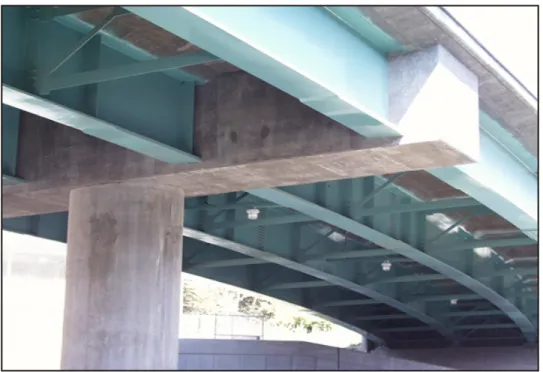
The Steel Girder and FBT 72 alternatives will use a standard multi-column pier supported on pile footings. The depth of the pier cap will taper between the columns for heightened aesthetics. See Figure 7-1, Figure 7-3, and Figure 7-4 for elevation views of this pier with each superstructure alternative.
3.6.2
CIP Concrete Box Girder Alternative
A major advantage of the cast-in-place concrete box alternative is that pier caps are not required. Internal diaphragms will be provided to transmit the reactions from the superstructure to the columns. See Figure 7-2 for an elevation view of this pier.
Interstate 4 Interchange at Maitland Boulevard 3-7 Bridge Development Report – Eastbound Maitland Boulevard over I-4
Chapter 6
3.7 Foundation
Constructability
Given the soils encountered in the preliminary geotechnical investigation, 24-inch prestressed piles are expected to be readily installed by experienced bridge contractors. Their modest weight and UBC enables these piles to be transported, lifted and driven by commonly available construction equipment. Noise and vibrations can be reduced by preforming and “bagging the pile” that involves wrapping the hammer and pile in an insulated shroud.
COST ESTIMATE
I-4
I-4
I-4
MAITLAND BOULEVARD
MAITLAND BOULEVARD
I-4
I-4
I-4
Interstate 4 Interchange at Maitland Boulevard 4-1 Bridge Development Report – Eastbound Maitland Boulevard over I-4
Chapter 6
4.0 COST
ESTIMATE
Preliminary quantities were calculated for each superstructure alternative. These quantities were then multiplied by unit prices to estimate the superstructure cost for each alternative. The quantity calculations are included in Appendix A.
4.1
Unit Costs (BDR Cost Estimating Guidelines)
During the corridor-wide structures coordination meeting on March 1, 2005, it was decided that unit costs from the January 2004 Structures Design Guidelines, BDR Cost Estimating Section would be used, and supplemented when necessary by FDOT pay item cost history data. The primary goal of developing costs for the BDR was to identify the relative costs between various alternatives using the BDR Cost Estimating unit prices.
4.2 Other
Costs
The BDR Cost Estimating Guidelines gives a method to measure the relative construction cost of each alternative. The guidelines do not take into account the maintenance costs associated with particular bridge superstructure types or costs to the public due to travel delays during construction. While these costs are not quantified in this report, it should be noted CIP concrete box and FBT 72 spliced girder superstructures have lower average maintenance costs over the life span of the bridge than steel girder superstructures. The CIP concrete box girder superstructure will result in more traffic delays and associated costs due to the constricted opening under the falsework.
4.3 Cost
Summary
The total estimated construction cost of the bridge for the four alternatives with aesthetic treatments is:
− Alternative 1 – FBT 72 Spliced Girder $3,916,000
− Alternative 2 – CIP Concrete Box $4,401,000
− Alternative 3 – Steel Plates $4,307,000
− Alternative 4 – Steel Box $4,177,000
Maitland Blvd. over I-4 FPID 242484-6-32-1 Estimated Quantities for BDR
Pay Item Description Unit Unit Price Quantity Subtotal Quantity Subtotal Quantity Subtotal Quantity Subtotal
Number
Additional Costs
110 - 3 Structures, Removal of Existing SF $ 12.00 26729.4 $ 320,752.25 26729.4 $ 320,752.25 26729.4 $ 320,752.25 26729.4 $ 320,752.25
400 - 2 - 10 Conc Class II (Approach Slabs)(2 req.) CY $ 240.00 203.2 $ 48,771.30 203.2 $ 48,771.30 203.2 $ 48,771.30 203.2 $ 48,771.30
415 - 1 - 9 Reinforcing Steel (Approach Slabs) LB $ 0.46 41659 $ 19,163.06 41659 $ 19,163.06 41659 $ 19,163.06 41659 $ 19,163.06
Aesthetic Treatments on Bridge* SF $ 100.00 3984 $ 398,366.66 0 $ - 4145 $ 414,516.66 0 $
-Total Additional Cost = $ 787,053.26 $ 388,686.60 $ 803,203.26 $ 388,686.60
Superstructure
400 - 4 - 4 Class IV Concrete (Superstructure) CY $ 425.00 737.9 $ 313,617.59 0.0 $ - 737.9 $ 313,617.59 737.9 $ 313,617.59
400 - 4 - 4 Class IV Concrete (CIP Superstructure) CY $ 775.00 74.7 $ 57,868.50 1804.2 $ 1,398,237.10 0.0 $ - 0.0 $
-415 - 1 - 4 Reinforcing Steel (Superstructure) LB $ 0.46 166582 $ 76,627.50 330943 $ 152,233.76 151274 $ 69,586.21 151274 $ 69,586.21
400 - 7 Bridge Floor Grooving SY $ 2.50 3574.7 $ 8,936.66 3574.7 $ 8,936.66 3574.7 $ 8,936.66 3574.7 $ 8,936.66
400 - 147 Composite Neoprene Bearing Pads CF $ 500.00 13.5 $ 6,750.00 7.3 $ 3,666.80 15.0 $ 7,500.60 11.1 $ 5,555.98
450 - 1 - 272 Prestressed Beams (Bulb-T)(72)(Modified) LF $ 180.00 2907.0 $ 523,260.00 0.0 $ - 0.0 $ - 0.0 $
-462 - 2 - 11 Post-tensioning Strands (Transverse) LB $ 1.82 0 $ - 30260 $ 55,073.64 0 $ - 0 $
-462 - 2 - 11 Post-tensioning Strands (Longitudinal) LB $ 1.53 81315 $ 124,411.34 95347 $ 145,880.91 0 $ - 0 $
-461 - 113 - 15 Multirotational Bearing Assembly (F&I) (1001-1250 Kips) EA $ 5,670.00 0 $ - 0 $ - 0 $ - 4 $ 22,680.00
460 - 2 - 1 Struct Steel (Carbon) LS(LB) $ 1.60 0 $ - 0 $ - 40976 $ 65,561.76 43074 $ 68,919.14
460 - 2 - 2 Struct Steel (Low Alloy) (Plates) LS(LB) $ 1.21 0 $ - 0 $ - 745020 $ 901,474.20 0 $
-460 - 2 - 2 Struct Steel (Low Alloy) (Boxes) LS(LB) $ 1.54 0 $ - 0 $ - 0 $ - 783172 $ 1,206,084.88
460 - 7 - 4 Expansion Joint Seal LF $ 106.00 169.0 $ 17,914.00 169.0 $ 17,914.00 169.0 $ 17,914.00 169.0 $ 17,914.00
521 - 5 - 1 Traffic Railing Barrier (32" F-shape) LF $ 44.00 766 $ 33,704.00 766 $ 33,704.00 766 $ 33,704.00 766 $ 33,704.00
Total Superstructure Cost = $ 1,163,089.60 $ 1,815,646.88 $ 1,418,295.02 $ 1,746,998.45
Substructure - per End Bent
400 - 4 - 5 Concrete Class IV (Substructure) CY $ 550.00 67.1 $ 36,883.46 67.1 $ 36,883.46 67.1 $ 36,883.46 67.1 $ 36,883.46
415 - 1 - 5 Reinforcing Steel (Substructure) LB $ 0.46 9053 $ 4,164.48 9053 $ 4,164.48 9053 $ 4,164.48 9053 $ 4,164.48
455 - 34 - 5 Concrete Piling (24 in) LF $ 65.00 800 $ 52,000.00 900 $ 58,500.00 700 $ 45,500.00 700 $ 45,500.00
455 - 143 - 5 Concrete Test Piles (24 in) LF $ 190.00 115 $ 21,850.00 115 $ 21,850.00 115 $ 21,850.00 115 $ 21,850.00
455 - 137 Test Load (Dynamic) EA $ 2,000.00 1 $ 2,000.00 1 $ 2,000.00 1 $ 2,000.00 1 $ 2,000.00
Cost Per End Bent = $ 116,897.93 $ 123,397.93 $ 110,397.93 $ 110,397.93
Number of End Bents = 2 2 2 2
End Bent Total = $ 233,795.87 $ 246,795.87 $ 220,795.87 $ 220,795.87
Substructure - per Pier
400 - 4 - 5 Concrete Class IV (Substructure) CY $ 550.00 68.3 $ 37,583.33 35.8 $ 19,678.59 68.3 $ 37,583.33 68.3 $ 37,583.33
400 - 4 - 25 Concrete Class IV (Mass) (Substructure) CY $ 314.00 321.1 $ 100,825.98 215.5 $ 67,672.81 321.1 $ 100,825.98 321.1 $ 100,825.98
415 - 1 - 5 Reinforcing Steel (Substructure) LB $ 0.46 75940 $ 34,932.34 49003 $ 22,541.41 75940 $ 34,932.34 75940 $ 34,932.34
455 - 34 - 5 Concrete Piling (24 in) LF $ 65.00 2560 $ 166,400.00 2480 $ 161,200.00 2560 $ 166,400.00 2560 $ 166,400.00
455 - 143 - 5 Concrete Test Piles (24 in) LF $ 190.00 95 $ 18,050.00 95 $ 18,050.00 95 $ 18,050.00 95 $ 18,050.00
455 - 137 Test Load (Dynamic) EA $ 2,000.00 1 $ 2,000.00 1 $ 2,000.00 1 $ 2,000.00 1 $ 2,000.00
462 - 2 - 13 Post-tensioning Strands LB $ 10.00 0 $ - 0 $ - 0 $ - 0 $
-548 - 13 Cofferdam (Temporary sheet piles) SF $ 8.00 5700 $ 45,600.00 6480 $ 51,840.00 5700 $ 45,600.00 5700 $ 45,600.00
Cost Per Pier = $ 405,391.65 $ 342,982.81 $ 405,391.65 $ 405,391.65
Number of Piers = 1 1 1 1
Pier Total = $ 405,391.65 $ 342,982.81 $ 405,391.65 $ 405,391.65
Total Bridge Cost = $ 1,802,277.11 $ 2,405,425.56 $ 2,044,482.54 $ 2,373,185.97
Cost per Sq. ft = $ 64.07 $ 85.52 $ 72.69 $ 84.37
Total Bridge Cost (With Additional Cost)= $ 2,589,330.38 $ 2,794,112.16 $ 2,847,685.80 $ 2,761,872.57
Cost per Sq. ft (With Additional Cost) = $ 92.06 $ 99.34 $ 101.24 $ 98.19
Contingencies(25%) = $ 647,332.59 $ 698,528.04 $ 711,921.45 $ 690,468.14
Subtotal = $ 3,236,662.97 $ 3,492,640.20 $ 3,559,607.25 $ 3,452,340.71
Urban Construction (6%) = $ 194,199.78 $ 209,558.41 $ 213,576.43 $ 207,140.44
Construction over Traffic (20% for CIP Box 15% for steel and FBT Spliced Girder )= $ 485,499.45 $ 698,528.04 $ 533,941.09 $ 517,851.11
Grand Total Without Aesthetic Treatments = $ 3,313,832.62 $ 4,400,726.65 $ 3,680,168.32 $ 4,177,332.26 Grand Total = $ 3,916,362.20 $ 4,400,726.65 $ 4,307,124.77 $ 4,177,332.26
Cost per Sq. ft (Grand Total) = $ 139.23 $ 156.45 $ 153.13 $ 148.51
* Optional Cost for Aesthetic Treatments on Bridge **MOT and Mobilization Costs are not included in this estimate
Table 4-1
Estimated Construction Cost for Eastbound Maitland Boulevard over I-4
Alternative 1 FBT 72 Spliced Girder Alternative 2 CIP Concrete Box Girder Alternative 3 Steel Plate Girders Alternative 4 Steel Box Girders
TRAFFIC CONTROL
I-4
I-4
I-4
MAITLAND BOULEVARD
MAITLAND BOULEVARD
I-4
I-4
I-4
Interstate 4 Interchange at Maitland Boulevard 5-1 Bridge Development Report – Eastbound Maitland Boulevard over I-4
Chapter 6
5.0 TRAFFIC
CONTROL
Traffic control is a major element in the successful construction of the I-4/Maitland Boulevard interchange. All alternatives will use the same proposed traffic phasing to construct the bridge carrying Maitland Boulevard (eastbound) over I-4.
• Construct temporary pavement for I-4 (eastbound) to the immediate east of
existing pavement (Phase I Stage 1).
• Shift I-4 (eastbound) traffic to east to create room for construction of foundations
and piers for both bridges carrying Maitland Boulevard over I-4. Then, construct piers for Maitland Boulevard bridges (eastbound and westbound) over I-4 (Phase I Stage 2).
• Construct westbound Maitland Boulevard over I-4 Bridge (Phase II Stages 3 and
4).
• Shift westbound Maitland Boulevard traffic from existing bridge to the new
westbound bridge and demolish existing westbound bridge (Phase III Stage 1).
• Construct new eastbound Maitland Boulevard over I-4 Bridge (Phase III Stage 2).
• Shift eastbound Maitland Boulevard traffic to the new bridge (Phase III Stage 3).
• Demolish existing bridge (Phase IV Stage 3).
5.1 Foundation
Construction
The traffic control required to construct the end bents and piers will be the same for all alternatives. Construction areas required to construct the foundations will be provided in the maintenance of traffic scheme. This will also create a lay-down area for piling as well as provide room for the necessary construction equipment. See Figure 5-1 for a detail of lane shifts and construction area.
Foundation construction should not impact Maitland Boulevard traffic since it is carried by existing structures that are an adequate distance away.
5.2
FBT 72 Spliced Girder Alternative
Falsework will support girder segments as they are erected. Rolling roadblocks will be required when beams are set and the cast-in-place concrete deck is poured over the I-4 travel lanes. Section 6 shows the expected location of the falsework required to support the FBT 72 pier section. Girder erection will be accomplished using ground cranes.
Interstate 4 Interchange at Maitland Boulevard 5-3 Bridge Development Report – Eastbound Maitland Boulevard over I-4
Chapter 6
5.3
CIP Concrete Box Superstructure Construction
Overhead formwork supported by temporary falsework spanning I-4 traffic is required for this alternative. The conceptual scheme for the formwork is shown in Section 6. Construction of the falsework and formwork over traffic will be restricted to nighttime hours to reduce traffic delays.
The proposed erection scheme for the eastbound Maitland Boulevard bridge over I-4 utilizes proven techniques that have been used in other parts of the country for cast-in-place concrete box bridges over traffic. Vertical clearance during construction was checked since an additional depth of 2 feet will be needed to build this alternative over I-4 traffic. The proposed I-I-4 mainline cross section is about 2 feet higher than the existing I-4 cross section. This effectively adds 2 feet of extra clearance under the proposed superstructure during construction since the structures will be constructed over the existing I-4.
The major disadvantage of this alternative is the limited roadway width under the formwork. Temporary columns close to traffic will be needed to support falsework beams. These beams will span over I-4 traffic to support the superstructure formwork. The temporary roadway typical section, consisting of one 12-foot lane, two 11-foot lanes and two 2-foot shoulders, will shorten the falsework span and reduce the beam depth but will also impair traffic flow. An extra 2 feet behind the traffic barriers will be used to further protect the temporary piers that will be founded on steel pipe piles. It is necessary to minimize the depth of the steel support beams over traffic to maintain vertical clearance over I-4. The current concept calls for at least 16 feet of vertical clearance to the temporary girders that support the formwork, which is consistent with FDOT PPM, Chapter 2 requirements. 6 inches of additional clearance, intended to accommodate future resurfacing, need not be provided during the construction stage.
5.4
Steel Superstructure Construction
The steel erection will be accomplished using ground cranes. The cranes will be located adjacent to the superstructure in the median or east or west of the I-4 travel lanes. Additionally, traffic will not be permitted beneath the position of the superstructure where deck concrete is being placed. The use of nighttime rolling roadblocks along I-4 will be used to create construction windows to pour the deck and place the girders. Construction during off-hours will mitigate inconveniences to the public. This type of construction is standard with steel girder bridge alternatives.
CONSTRUCTABILITY
I-4
I-4
I-4
MAITLAND BOULEVARD
MAITLAND BOULEVARD
I-4
I-4
I-4
Interstate 4 Interchange at Maitland Boulevard 6-1 Bridge Development Report – Eastbound Maitland Boulevard over I-4
Chapter 6
6.0 CONSTRUCTABILITY
6.1 Foundations
The constructability of the foundations is equivalent for all alternatives. Driving prestressed concrete piles is considered standard bridge construction. Given the adequate lay-down area adjacent to the end bents, the delivery and storage of material will not be a significant issue.
6.2 Superstructure
6.2.1
Florida Bulb-T 72 Spliced Girders
Falsework will support the pier girder section in locations away from traffic until the end girder sections are spliced. Steel strongbacks will aid in connecting these two sections until the last section over the main span can be dropped in and closure pours cast. The spliced beams will be post-tensioned in two stages and use three 3½-inch ducts each containing twelve 0.6-inch strands. The post-tensioning tendons will be stressed before construction of the end bent backwalls. See Figure 6-1 for the construction sequence.
6.2.2
CIP Concrete Box Girders
The principal challenge for the CIP concrete box girder alternative is to span the existing lanes of I-4 with temporary falsework, while maintaining the necessary minimum vertical clearance (16 feet based on AASHTO and PPM requirements when resurfacing/overlay is not expected). The alignment of I-4 relative to the proposed eastbound Maitland Boulevard alignment makes these falsework spans approximately 50 feet over both westbound and eastbound I-4. The temporary steel support beams and most of the formwork can be reused from the westbound Maitland Boulevard structure. See Figure 6-2 for the falsework concept for the CIP concrete box alternative.
6.2.3
Steel Girder Alternatives
Common construction methods for continuous steel girder bridges will be used to erect the bridge superstructure. The lack of post-tensioning, as well as a lack of any falsework requirements for CIP concrete box construction, will speed the construction of these alternatives.
AESTHETICS
I-4
I-4
I-4
MAITLAND BOULEVARD
MAITLAND BOULEVARD
I-4
I-4
I-4
Interstate 4 Interchange at Maitland Boulevard 7-1 Bridge Development Report – Eastbound Maitland Boulevard over I-4
Chapter 6
7.0 AESTHETICS
The Maitland Boulevard bridges over I-4 will be highly visible due to the large traffic volume passing beneath the structures from one of the busiest transportation corridors in the state. The FDOT and design team are committed to providing attractive yet cost-effective features to enhance the immediate surroundings.
It is generally accepted that the overall form of the structure has the most significant impact on aesthetics. Fortunately, the shape and curvature of the new bridges will create an inherently attractive structure.
The column shape is controlled by roadway shoulder constraints. The proposed circular columns of the CIP concrete box girder alternative will blend well with the subtle overall curves of the structure provided by the horizontal and vertical geometry of the bridge alignment. The CIP concrete box alternative will have one less column than the other alternatives. This alternative also will not require pier caps since these are integral with the box.
The piers required for the steel girder and FBT 72 spliced girder alternatives will use elements from the FDOT preferred details to enhance the aesthetics of the substructure. The pier cap will vary in height between the columns and use a radius on the bottom to further the curve motif of the bridges. See Figure 7-1 through Figure 7-4 for a conceptual example of a proposed pier with each superstructure alternative.
FDOT has an option to add fiberglass reinforced plastic panels or precast concrete fascia panels to the fascia on the FBT 72 spliced girders and steel plate girder alternatives to improve aesthetics. Fiberglass reinforced plastic panels can be molded into many different shapes and use a variety of surface finishes. Figure 7-7 shows a rendering of the fiberglass reinforced panel configuration proposed for the FBT 72 spliced girders and steel plate girder alternatives.
Long term maintenance for the fiberglass reinforced plastic panels must be considered when developing details. Connections made between panels and to the structure need to be designed not to corrode or become loose.
Columns and superstructure elements will receive either a Class V or concrete stain finish. The color and texture of the finish will be selected after coordinating with the architect and the project aesthetics committee. The preliminary concept for the proprietary walls is to have a recessed diamond finish.
Steel box girders are preferred over the plate girders because of the smooth bottom soffit and uncluttered appearances. The box girders have discontinuities in the form of end cross frames. The simple form of cast-in-place concrete box girders offers improved aesthetics to steel plate, steel box girder, and FBT 72 spliced girder bridges. The large overhangs, smooth bottom soffit and modest substructures create a series of smooth lines that follow the alignment of the bridge. Figure 7-5 and Figure 7-6 show examples of each superstructure type.
4
M ai tla nd B lv dSR 400 (I-4) ORANGE AND SEMINOLE COUNTIES Fin No. 242484-6-32-01
Figure 7-1
North of K
ennedy Boulevard
to north of Maitland Boulevard
Bridge A
esthetics
FBT 72 Spliced Girder Alternative
60’ 12’ Shoulder 12’ Shoulder 8’
4
M ai tla nd B lv dSR 400 (I-4) ORANGE AND SEMINOLE COUNTIES Fin No. 242484-6-32-01
Figure 7-2
North of K
ennedy Boulevard
to north of Maitland Boulevard
Bridge A
esthetics
CIP Concrete Bo
x Girder Alternative
60’ 12’ Shoulder 12’ Shoulder 7’-4”4
M ai tla nd B lv dSR 400 (I-4) ORANGE AND SEMINOLE COUNTIES Fin No. 242484-6-32-01
Figure 7-3
North of K
ennedy Boulevard
to north of Maitland Boulevard
Bridge A
esthetics
Steel Plate Girder Alternative
60’ 6’ 12’ Shoulder 12’ Shoulder F a u x A rc h F a sc ia
4
M ai tla nd B lv dSR 400 (I-4) ORANGE AND SEMINOLE COUNTIES Fin No. 242484-6-32-01
Figure 7-4
North of K
ennedy Boulevard
to north of Maitland Boulevard
Bridge A
esthetics
Steel Bo
x Girder Alternative
60’ 6’ 12’ Shoulder 12’ Shoulder4
Maitland Blvd
SR 400 (I-4) Fin No. 242484-6-32-01
ORANGE AND SEMINOLE COUNTIES
Figure 7-5
North of Kennedy Boulevard to north of Maitland Boulevard
Steel Plate Girder Superstructure
Steel Box Girder Superstructure
4
Maitland Blvd
SR 400 (I-4) Fin No. 242484-6-32-01
ORANGE AND SEMINOLE COUNTIES
Figure 7-6
North of Kennedy Boulevard
to north of Maitland Boulevard
Bridge Aesthetics Photos
Cast-in-place Box Superstructure
4
M ai tla nd B lv dSR 400 (I-4) ORANGE AND SEMINOLE COUNTIES Fin No. 242484-6-32-01
Figure 7-7
North of K
ennedy Boulevard
to north of Maitland Boulevard
M S E W a ll F a u x A rc h F a sc ia
Fiberglass P
anel R
endering
Interstate 4 Interchange at Maitland Boulevard 7-9 Bridge Development Report – Eastbound Maitland Boulevard over I-4
Chapter 6
Both concrete superstructure alternatives use constant depth superstructure for the eastbound Maitland Boulevard bridge, while they utilize a variable depth superstructure section over the piers for the westbound Maitland Boulevard bridge. This will create a disharmony between two adjoining structure perspectives. The depth of steel alternatives for the two Maitland Boulevard structures is similar, and will not create any contrast.
EVALUATIONS
I-4
I-4
I-4
MAITLAND BOULEVARD
MAITLAND BOULEVARD
I-4
I-4
I-4
Interstate 4 Interchange at Maitland Boulevard 8-1 Bridge Development Report – Eastbound Maitland Boulevard over I-4
Chapter 6
8.0 EVALUATIONS
An evaluation matrix considering cost, traffic control, constructability and aesthetics was created to determine the ideal structure for the eastbound Maitland Boulevard over I-4 bridge. The relative comparison of alternatives is explained below and the completed matrix is shown as Table 8-1.
Table 8-1
Alternative Evaluation Matrix
Item FBT 72 CIP Box Steel Plate Steel Box
Cost √
Traffic Control √ √ √
Constructability √ √ √
Aesthetics √ √
8.1 Cost
Cost is recognized as an important selection criterion for District 5 and FDOT as a whole. The District has emphasized the need to reduce project costs so that a greater number of projects could be delivered to the public.
The actual cost will depend on the construction market at the time the project is bid, which is difficult to predict. The cost comparison of the alternatives using the 2004 Structures Design Guidelines unit prices indicates that the FBT 72 spliced girder alternative is a more cost efficient bridge alternative. See Table 4-1 for the Estimated Construction Cost Comparison.
8.2 Traffic
Control
It is important to construct projects with a minimum inconvenience to the public. All four alternatives will use nighttime rolling road blocks when construction over traffic is required.
The concrete cast-in-place box alternative will have a bigger impact than the steel and FBT 72 superstructure alternatives. Due to the presence of the falsework columns, the opening for I-4 traffic will remain constricted for several months, compared to other alternatives. Steel girders and FBT 72 spliced girder erection durations are much shorter than the duration required for erection and dismantling of falsework and formwork and for casting and post-tensioning the cast-in-place box girders. The falsework column required for FBT 72 alternative will be located in the existing I-4 median and away from the traffic, and does not impose any restrictions.
Interstate 4 Interchange at Maitland Boulevard 8-2 Bridge Development Report – Eastbound Maitland Boulevard over I-4
Chapter 6
8.3 Constructability
The construction of both steel alternatives is typical for continuous steel girder bridge construction and offers no unusual challenges. The construction of spliced girder alternatives is also typical for this type of bridge construction.
The steel girder and FBT 72 spliced girder alternatives are preferred. From a fabrication standpoint the steel box girders are much more complex than steel plate girders. Larger amounts of formwork and falsework are needed for the CIP concrete box alternative than the other alternatives.
8.4 Aesthetics
The CIP concrete box and steel box girder alternatives offer higher aesthetics as their closed bottom soffits create smooth lines that accentuate the simple form of the structure. It should be noted that both concrete superstructure alternatives utilize constant depth superstructure for the eastbound Maitland Boulevard bridge, while they utilize a variable depth superstructure section over the piers for the westbound Maitland Boulevard bridge. This will create a disharmony between two adjoining structure perspectives. The depth of steel alternatives for the two Maitland Boulevard structures is similar, and will not create any contrast.
8.5 Recommendation
The recommended superstructure is the FBT 72 spliced girder alternative due to its competitive cost, constructability, and ease of traffic control. The recommended substructure is end bents and piers founded on 24-inch prestressed concrete piles. Permanent proprietary walls are recommended at the bridge abutments.
The total estimated construction cost for the new eastbound Maitland Boulevard bridge over I-4 including aesthetic treatment is $3,916,000.