1. INTRODUCTION
Ultra Low and No Cement Castables (ULCC, NCC) have been used increasingly in high temperature industries due to low content of CaO and consequently high temperature properties [1]. Low melting-point eutectic phases are often formed in alumina refractory castables by reaction of CaO, SiO2 and Al2O3. Since these phases demolish refractoriness and corrosion resistance of refractories, they are not desirable [1, 2]. Therefore, one of approach to produce high performance refractory castables is reducing CaO content by decreasing the amount of Calcium Aluminate Cement (CAC) as a main binder in refractory castables [3]. Recently, many researchers have focused on the influence of nanosilica as a new binder in the castables [4, 5, 6]. Colloidal silica nanoparticles (nanosilica) are used in the form of silica sol which is an aqueous dispersion of nanosized and amorphous silica
significantly deteriorate the mechanical properties [3, 9, 10]. While silica sol is adding to refractory mixtures, the nanosized silica particles can encapsulate the aggregates by gelation mechanism [1, 8]. The free silanol groups (Si-OH) on the nanosilica surface change to siloxane bond (Si-O-Si) and subsequently three dimensional networks is formed by this mechanism. The mechanism also may help to prevent the prementioned heterogeneities and flaws creation [9, 11].
There are some major advantages in use of nanosilica in refractory castables such as short mixing time, high permeability, high drying rate and low spalling risk [5, 11]. Moreover, high reactivity of nanosized silica may promote the mullite formation in alumina refractory castables [8].
Adding silica sol to refractory castable doesn’t produce any normal chemical products such as calcium aluminate hydrates in CAC bonded and alumina gel in hydratable alumina bonded (HAB)
INFLUENCE OF NANO SILICA ON PROPERTIES AND
MICROSTRUCTURE OF HIGH ALUMINA ULTRA-LOW CEMENT
REFRACTORY CASTABLES
H. Yaghoubi1, H. Sarpoolaky1,*, F. Golestanifard1and A. Souri2 * [email protected]
Received: July 2011 Accepted: January 2012
1Department of Metallurgy and Ceramic, Iran University of Science and Technology, Tehran, Iran. 2Malayer University, Malayer, Iran.
Abstract:Colloidal silica bonded refractory castables have been developed recently. It was found that colloidal silica is one of the best binders can substitute other binders such as cement in No Cement Castable (NCC) and Ultra Low Cement Castable (ULCC) refractories. Also composition of colloidal silica with appropriate additives resulted in a gel form which makes the initial strength. Moreover, the nano size silica particles are extremely reactive in high alumina castables and may encourage the mullite formation in the microstructure. In the current study, four castables were prepared. The sample containing 6wt % microsilica was a reference, then microsilica was replaced by different amount of colloidal silica (2.5, 5, 7.5 wt %). Silica and water content was kept constant. It’s concluded that the castables containing the optimum amount of silica sol shows remarkable increase in both castable fluidity and mechanical strength (CCS and MOR) in dried and sintered state. It was also found that nanosilica particles increase the rate of needle-shaped mullite formation during sintering at 1400°C. According to FTIR results, the addition of Calcium Aluminate Cement (CAC) to the silica sol may be responsible for the increment of siloxane bridges (Si-O-Si).
to increase the drying rate and decrease spalling risk of refractory castables. Furthermore, these gel-like structures can improve mechanical strength of the dried samples comparing to the castables containing CAC in which longer time is needed for the dissolution/precipitation process of cement. [5, 11].
The high specific surface area of nanosized silica particles (~200 m2/gr) can promote the sintering rate of refractory castables [8, 11]. Midgley et al have observed the formation of stratlingite phase (CaO.Al2O3.SiO2.H2O) in the refractory containing both silica sol and CAC [13].
The purpose of this research is to investigate the influence of colloidal silica particles (nanosilica) on properties and microstructure of high-alumina ultra low cement refractory castables.
2. EXPERIMENTAL PROCEDURE
2. 1. Materials
The raw materials used in this work are graded
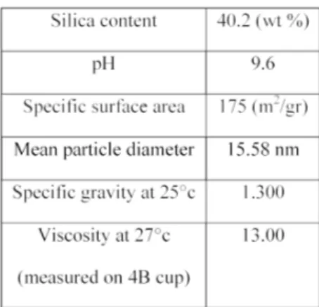
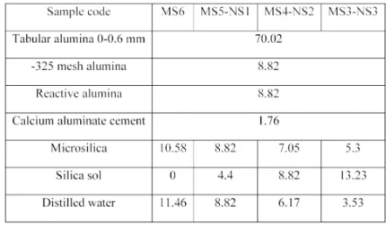
tabular alumina, ultra fine alumina (<45 µm), reactive alumina, microsilica and high alumina cement of secar 71 from Lafarge Co. Silica sol as a nanostructure binder which is contained 40%wt solid nanosilica particles and 60%wt water was also added to the mixtures. The original chemical composition and codes for different samples are presented in Table 1. The codes are acronym, formed from the amount of Microslica (MS) and Nanosilica (NS).
Substituting microsilica by nano silica may change the size of silica particles from micro to nanometer, however; the amount of silica was kept constant in all samples. The XRF analysis shows that the CaO content in silica sol is very low (0.022%) in comparison to microsilica, on the other hand the silica sol is a free-Cao binder. The silica sol characteristics provided by the manufacturer are presented in table 3.
2. 2. Castable Preparation
According to table 1, four commercial ULCC castables were prepared by gradually adding distilled water and silica sol to the mixture of raw
Table 1.Chemical composition of each sample Table 3. Silica sol characteristics
materials in a Hobart mixer. The optimal content of citric acid (0.02 %wt) and Castament FS20 (0.1 %wt) predissolved in the water was used for mixing the castable samples.
The samples mixed for 3 minutes with controlled water and silica sol were cast in moulds under vibration. After that the moulds were kept in the plastic chamber to cure at room temperature for 24 hr. The samples were removed from the moulds and cured for another 24 hr at room temperature and dried at 110 ºC for one more 24 hr. Finally, they were sintered at 1200, 1400 and 1600 ºC for 3 hours in ambient atmosphere.
2. 3. Characterizations
The fluidity of samples was measured according to ASTM C230 method immediately after wet mixing. To evaluate the mechanical properties, cold crushing strength (CCS) and modulus of rupture (MOR) were also measured based on EN 1402-6.
Although, the setting mechanism of silica sol or colloidal silica has been reviewed by researchers [6] there is limited information about how to set it in presence of cement; therefore, two dried samples were investigated by FTIR technique, the first sample contained 7.5 gr colloidal silica and 1 gr cement (marked as CS-Ce), and the other one has 7.5 gr colloidal silica with no cement (marked as CS).
Matrix of the refractory samples can be
defined as -a mixture of fine and ultra fine particles- which are responsible for bonding the coarse refractory aggregates [14]. Table 4 shows the chemical composition of our matrix materials, i.e. fine alumina, reactive alumina, CAC, microsilica and silica sol mixture.
Phase analysis of the dried and fired samples as well as the matrices were investigated by X-ray diffraction (XRD) technique after crushing and passing via sieve mesh size 180. The microstructural observation was studied by the use of scanning electron microscopy SEM (Cambridge Stereoscan 360) after polishing and coating the mounted samples.
3. RESULT AND DISCUSSION
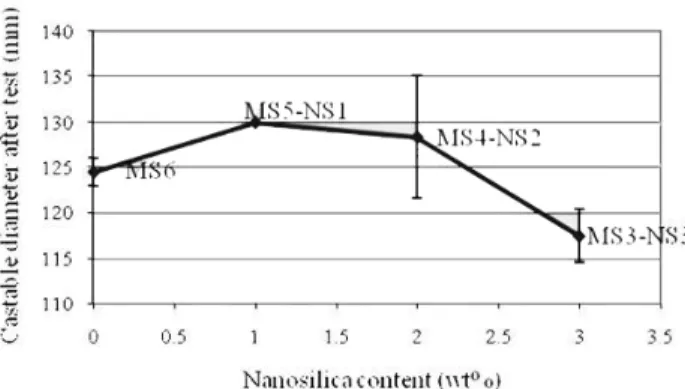
Figure 1 shows the influence of silica sol on the castable fluidity. The flow ability of MS5-NS1 and MS4-NS2 samples improved slightly in comparison to the reference sample. The MS3-NS3 sample reached to the minimum fluidity. By increasing silica sol, the castable fluidity at first increased (like the sample containing 2.5% and 5%wt silica sol) and then decreased dramatically (like the sample containing 7.5%wt silica sol).
It is indicated that silica sol may improve the alumina particles dispersion by electrostatic repulsion at basic condition, which is in accordance with the other reports [11, 14]; but in MS3-NS3 sample, the excessive viscous silica sol demolished fluidity. Based on the composition formula (Table 1), another reason
for decreasing fluidity in this sample might be the low content of microsilica as a filler and also free water. Since silica sol has 60%wt water, a balance between the SiO2 load (in both micro and nanosized) and the free water amount are necessary [11].
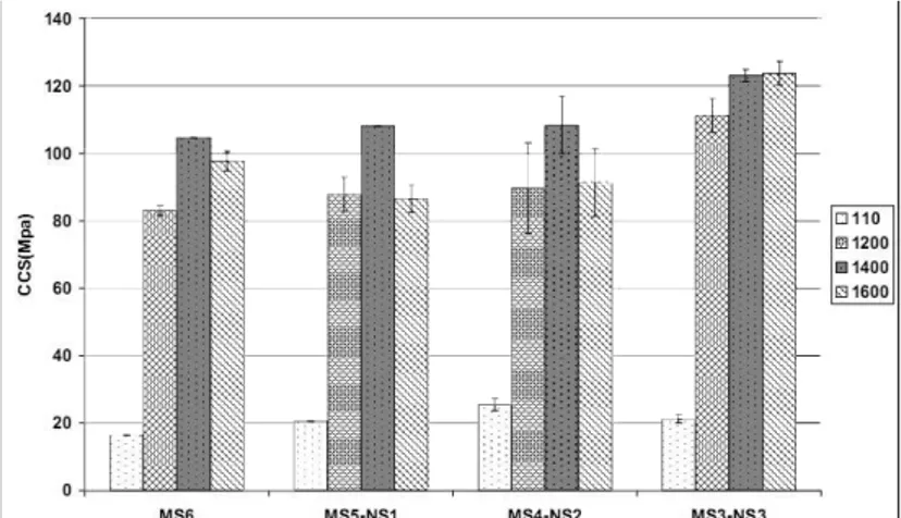
The effect of silica sol content on CCS and MOR at distinctive sintering temperatures is given in figure 2. By increasing silica sol, at first the mechanical strength (CCS, MOR) slightly increased (like the sample MS5-NS1 and MS4-NS2) after drying at 110oc, and then showed a little reduction (like the sample MS3-NS3). The strength increased because of introducing silica sol as a binding agent into the refractory composition. The silica sol bonding required water removal so that the gelation mechanism could take place normally after drying. Since the
water removal decrease the inter-particle separation distance, the nanosized silica particle collision and the formation of siloxane bond (Si-O-Si) will be increased [4]. The Ca2+ and Al3+ ions from the cement dissolution may act as gelling agent. These ions can reduce the overall net repulsion between the colloidal silica nanoparticles leading to accelerated gelation [14]. During gelation process, the hydroxyl groups (Si-OH) on the surface of nanometer silica particles transform to siloxane bonds (Si-O-Si), which resulted in a three-dimensional network [4]. This network encapsulates the alumina aggregates, so strength of castables after drying increases [11].
Optimum amount of silica sol has a key role where it behaves as a proper binder; specifically in refractory castable it should provide suitable
mechanical strength, without significant reduction in fluidity [14]. In the present study, the amount of silica sol in MS5-NS1 and MS4-NS2 samples could play binding role perfectly, but in MS3-NS3 sample the extra amount of silica sol ruined both fluidity and green mechanical strength. On the other word, 5% wt silica sol (MS4-NS2) in this refractory composition (Table 1) is the optimum content that can improve both fluidity and green mechanical strength.
Among all four samples, the one with 5% wt silica sol gives the maximum mechanical strength after drying. Probably, it is due to the simultaneous effect of gelling mechanism and formation stratlingite phase (CaO.Al2O3.SiO2.H2O). The phase is a product of silica sol and hydrated CAC reaction. This phase detected by XRD analysis [13].
Mechanical strength (CCS) after sintering at 12000C increased slowly by increasing amount of silica sol. This can be explained by the high specific surface area of nano-sized silica particles in the castable which increased the system’s reactivity, or the castable sinterability [11].
Mechanical strength (CCS, MOR) improved by increasing silica sol after sintering at 1400 ºC. It is can be explained by the reaction of nanosized silica particles with microfine alumina resulting
(XRD). After drying at 110 ºC, the hydration product C2AH8 (2CaO.Al2O3.8H2O) could be detected only in MS6 and MS5-NS1 sample. The stratlingite phase (CaO.Al2O3.SiO2.H2O) appeared in the XRD pattern of the MS4-NS2 sample; in addition, this phase could be detected in MS3-NS3 sample in lower content. Formation of this phase in the presence of both silica sol and CAC also was reported in [13].The calcium aluminate silicate phase in the Anorthite form (CAS2) appeared in all samples after sintering at 1200 ºC.
XRD results revealed mullite (A3S2) formed in all samples but the amount of mullite was increased by presence of silica sol. Since the XRD method normally is poor in quantitative analysis, it is hard to realize which sample exactly have more amount of mullite crystals; however, the mullite formation will be explained clearly with the assistance of SEM evaluation in the following.
It’s seen that the α-alumina was the major crystalline phase in the both dried and sintered samples.
Fig 3.a shows well dispersed alumina particles in the sample with optimum content of silica sol (MS4-NS2). The general microstructures of all the castable sample after drying at 110 ºC were
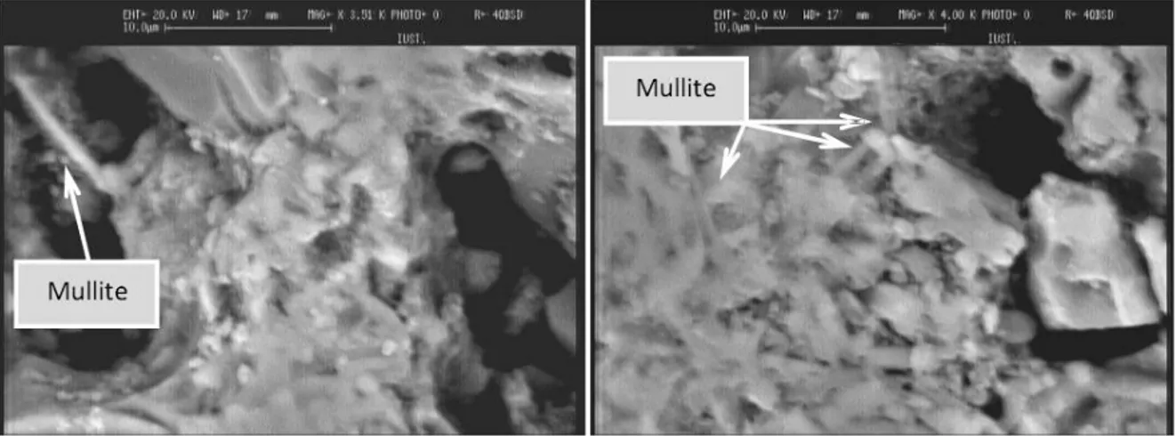
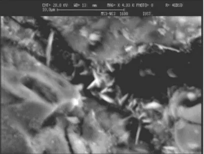
samples containing silica sol after sintering at 14000C, but these crystals couldn’t be seen in the sample without silica sol. Fig 4, 5a and b show the mullite crystals in the MS3-NS3, MS4-NS2 and MS5-NS1 samples, respectively. The poor-grown mullite in the MS6 sample fired at 1400 ºC
is shown in Fig 6.
Both SEM and mechanical strength results support this idea that the silica sol containing nano silica is responsible for proper growing of mullite crystals after sintering at 1400 ºC. From XRD, SEM and mechanical strength results Sample Code C2AH8 CAS3H8 CAS2 A3S2 TA
MS6 110 ++ - - - ++++ 1200 - - + - ++++ 1400 - - - + ++++ MS5-NS1 110 + - - - ++++ 1200 - - +++ - ++++ 1400 - - - ++ ++++ MS4-NS2 110 - ++ - - ++++ 1200 - - + - ++++ 1400 - - - +++ ++++ MS3-NS3 110 - + - - ++++ 1200 - - + - ++++ 1400 - - - ++ ++++
Abundant ++++ TA Tabular Alumina
Mediocre +++ C CaO
Little ++ A Al2O3
Very little+ S SiO2
Zero- H H2O
formation in the castables containing silica sol was increased because of high specific surface area of colloidal silica nanoparticles.
Comparing the mechanical strength of the samples sintered at 1400 ºC and 1600 ºC showed that their strength reduced by increasing sintering temperature. This extraordinary behavior was previously observed by other researchers that may be related to the dissolution of mullite crystals in the CAS liquid phase at more than 1512 ºC [6, 16, 17]. At 1500, the CAS (peritectic composition in CaO, Al2O3 and SiO2 ternary phase diagram) melts and starts attacking the
Fig. 4. Microstructure of MS3-NS3 sample showing well-growth mullite crystals
Fig. 5. a) Microstructure of the MS4-NS2 sample (b) the MS5-NS1 sample after sintering at 1400 ºC showing well-growth mullite crystals
phase by etching the sample in hydrofluoric acid. Figure 8(a and b) shows the FTIR graph for the sample (CS-Ce) and (CS), respectively. The free surface silanol groups (Si-OH) as well as siloxane bond (Si-O-Si) can be easily conceived from IR spectra in the range 400-4000 cm-1 as marked on the figure.
The gelation mechanism and siloxane bond (Si-O-Si) formation occurred in the CS-Ce sample more than that in the CS sample. As mentioned before, this may be related to the reduction of nanosilica interparticles net
repulsion due to the increment of Ca2+ and Al3+ from the cement dissolution [11, 14].
4. CONCLUSION
On the basis of overall results, it is concluded that the Optimum amount of silica sol is a major factor where it behaves as a binder. Specifically in refractory castable it should provide suitable mechanical strength, without significant reduction in fluidity. In the present study, 5% wt silica sol (like the MS4-NS2 sample) was known as the
optimum content because it improved both fluidity and mechanical strength.
By increasing silica sol, the castable fluidity begins to increase (like the sample containing 2.5% and 5%wt silica sol) and but it will be decreased dramatically in higher amounts (like the sample containing 7.5%wt silica sol). In addition, the simultaneous effect of gelation mechanism by optimum content of silica sol and the formation of stratlingite phase have resulted in the increment of castable mechanical strength. It may be concluded that the mullite crystals couldn’t grow appropriately during 3 hours sintering at 1400 ºC in the sample without silica sol. In this sample the mullite crystals could not be found by SEM evaluation, but the microstructural investigation reveals that the needle-shape mullite crystals were grown properly in samples containing nano silica by addition of silica sol.
The amount of IR transmission for the silica sol containing CAC sample was higher than that for the pure silica sol (CS) one. It’s related to the siloxan bond formation and gelling mechanism which could take place in the Ce-CS sample more than in the CS sample.
REFERENCES
1. Banerjee, S., “Monolithic Refractories: a
Comprehensive Handbook, Copyright by World Scientific Publishing,” Pages [113-117], 1998.
2. Banerjee, S., “Versatility of Gel-Bond
Casatable /Pumpable Refractories. Refractory Application.,” 2001, 6, 5.
3. Studart, A. R., Pandolfelli., V. C., “ In Situ
Coagulation of High-alumina Zero-cement Refractory Castables.,” J. Am .Ceram. Soc., 2002, 85, 8.
4. Anjos, R. D., Ismael, M. R., Oliveria, I. R.,
Pandolfelli, V. C.,” Workability and Setting Parameters Evolution of Colloidal Silica Bonded Refractory Suspension, Ceramic International., 2008, 34, 1.
Of Colloidal Silica Bonded Magnesite Castable Refractories,” IJMSE 2011, 8(1), pp. 25-31.
7. Bergna, H. E., Roberts, W. O, “ Colloidal Silica
Fundamentals and Applications, Chapter 2, The Language of Colloid Science and Silica Chemistry, ed. H.E. Bergna. CRC press, Taylor & Francis groups, Boca Raton, London, New Yourk, 2006, pp. 5-10.
8. Ismael, M. R., Salomao R., and Pandolfelli, V.
C., “Colloidal Silica Bonded Refractory Castables: Optimization of the Particle Size Distribution.,” Refractories Application and News, 2008, 13, 1.
9. Zawrah, M. F. M., Khalil, N. M.,“ Effect of
Mullite Formation on Properties of Refractory Castables,” Ceramic International, 2007, 27, 6.
10. Huger, M., Gault, C. and Chotard, T.,” High
Temperature Elastic Properties of Refractory Materials,” IJMSE 2007, Volume 4, Number 3.
11. Ismael, M. R., and Pandolfelli., V. C.,
“Refractory Castable Based on Colloidal Silica and Hydratable Alumina.,” Ame, Cer, Soc, Bul., 2002,86, 9.
12. Sarpoolaky, H., Ahari, K. G., Lee, W. E., “
Influence of In Situ Phase Formation on Microstructural Evolution and Properties of Castable Refractories,” Ceramic International., 2002, 28, 5.
13. Daspoddar, D., Das., S. K., “Effect of Silica Sol
of Different Routes on the Properties of Low Cement Castable,” Bull. Mater. Sci., 2003, 26, 2.
14. Innocentini, M. D. M., Pardo, A. R. F., and
Pandolfelli, V. C., “Permeability of High-Alumina Refractory Castables Based on Various Hydraulic Binders.,” J. Am. Ceram. Soc., 2002, 85, 6.
15. Kong, D., Yang, H.,” Dispersion Behavior and
Stabilization Mechanism of Alumina Powders in Silica Sol,” Materials Letters., 2004, 58.
16. Myhre, “Let's Make Mullite Matrix,”
Refractory Application and News., 2008, 13, 3.
17. Lee, W. E., Vieira, W., Zhang, S., Ghanbari
Ahari, K., Sarpoolaky, H. and Parr., C., “Castable Refractory Concretes.,” International