Enclosure to: NSAD-L-2010-039 Task JHS01
NSAD-R-2010-016
Live-Virtual-Constructive
Architecture Roadmap Implementation
Convergence Defining Architecture
Characteristics and Activities
NSAD-R-2010-016
Live-Virtual-Constructive
Architecture Roadmap Implementation
Convergence Defining Architecture
Characteristics and Activities
February 2010
Prepared by: R Saunders, JHU/APL DL Drake, JHU/APL P Gustavson, SimVentions JG Kovalchik, JHU/APL W Milks, Lockheed MartinR Murray, Boeing E Powell, SAIC SD Vick, JHU/APL
Page iii
TABLE OF CONTENTS
EXECUTIVE SUMMARY ... ES-1
1. REPORT DEVELOPMENT PROCESS ... 1
1.1 REPORT FORMAT... 2
1.2 CONVERGENCE APPROACH ... 2
2. CONVERGED EXECUTION ... 5
2.1 OVERVIEW OF THE DESIGN CONCEPT ... 5
2.2 MULTI-ARCHITECTURE INFRASTRUCTURE LIFECYCLE ... 7
2.3 PERSISTENT ENTITY OPERATIONS ... 8
2.4 MESSAGING OPERATIONS ... 10
3. CONVERGENCE ACTIVITIES ... 13
3.1 CONVERGENCE SYSTEMS ENGINEERING ... 13
3.1.1 CSE Requirements and Risk Analysis ... 13
3.1.2 CSE Enterprise Metadata Communication ... 13
3.1.3 CSE Prototype Evaluation ... 13
3.2 COMMON TRAINING INSTRUMENTATION ARCHITECTURE (CTIA) ... 13
3.2.1 CTIA Execution Interfaces ... 14
3.2.2 CTIA Interactions ... 15
3.2.3 CTIA Transfer of Ownership ... 15
3.3 DISTRIBUTED INTERACTIVE SIMULATION (DIS) ... 15
3.3.1 DIS to CSI Gateway... 16
3.3.2 DIS Gateway Requirements ... 16
3.4 HIGH LEVEL ARCHITECTURE (HLA)... 16
3.4.1 HLA Convergence Assessment ... 16
3.4.2 HLA RTI Implementation... 17
3.4.2 HLA Multi-Architecture Testing ... 17
3.5 TEST AND TRAINING ENABLING ARCHITECTURE (TENA) ... 18
3.5.1 TENA Enterprise Metadata ... 18
3.5.2 TENA Additional Features ... 18
3.5.3 TENA Ownership Transfer ... 19
4. COURSES OF ACTION ... 20
5. SUMMARY ... 21
APPENDIX A: REFERENCES ... A-1 APPENDIX B: ABBREVIATIONS AND ACRONYMS ... B-1
Convergence Defining Architecture Characteristics and Activities
Page iv
LIST OF FIGURES
Figure 1: LVC Simulations Interact with Real Command and Control to Provide a Rich
Environment for Engineering, Training, and Testing ... 1
Figure 2: Legacy Architecture Data Model Overlap ... 3
Figure 3: Common Distributed Architecture Overview ... 4
Figure 4: Conceptual Migration from Before Converged Execution to After ... 6
Figure 5: Layered Communication Diagram for the Converged Execution ... 6
Figure 6: The Multi-Architecture Infrastructure Lifecycle ... 8
Figure 7: Lifecycle of Object Types and Objects ... 9
Figure 8: Sequence Diagram for Multi-Architecture Object Deletion ... 10
Figure 9: Lifecycle of Message Types and Messages ... 11
Figure 10: Sequence Diagram for Multi-Architecture Message Passing ... 12
Figure 11: CTIA Convergence Focused on Central Range Operations Center ... 14
Figure 12: In Addition to Middleware, the TENA Architecture includes Servant and Proxy Objects Generated Automatically by TENA Tools ... 18
Page ES-1
EXECUTIVE SUMMARY
The Live-Virtual-Constructive (LVC) Architecture Roadmap (LVCAR) Study developed a vision for achieving significant interoperability improvements in LVC simulation environments. The study recommended activities proposed to lower the time and cost required to integrate multi-architecture events by building better bridges between the legacy architectures and making them more compatible with each other. An LVCAR Convergence Team (LVCAR-CT) has explored converging the current architectures. The recommended approach evolves each architecture to meet the needs of users while favoring common implementation techniques and solutions. Rather than make the current High Level Architecture (HLA) like the current Test and Training Enabling Architecture (TENA), the goal is to make future HLAs more like future TENAs. Subject matter experts (SMEs) from each architecture participated together on the LVCAR-CT. Each SME provided existing documentation resources and identified where in the documents to extract the key services and tools. The LVCAR-CT met to discuss these artifacts and agreed on a framework of common constructs through which to view them.
The LVCAR-CT has established an independent view of the current architectures. The next step was to determine what actions lead to convergence. The vision is that in 2015, new versions of the Common Training Instrumentation Architecture, Distributed Interactive Simulation, HLA, and TENA will come out that incorporate the results of the Convergence Initiative. The LVCAR-CT work does not stand alone. In particular, many preconditions, which are being pursued as part of related tasks, are necessary to achieve this vision.
This report describes the converged architecture envisioned by the LVCAR-CT in terms of how it would execute in a multi-architecture event. This converged execution contains: (1) simulations that need not be aware that multiple architectures are in use, (2) parts of the support infrastructure of the legacy infrastructures, and (3) a common shared library for communication. The LVCAR-CT selected this concept because it requires no changes to the simulations (which are the area of greatest Department of Defense modeling and simulation investment). As a result, changes under this proposed solution impact only a few infrastructure providers and require significantly less investment to achieve convergence.
Convergence Defining Architecture Characteristics and Activities Executive Summary
Page ES-2
Page 1
1. REPORT DEVELOPMENT PROCESS
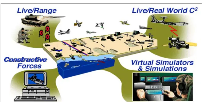
The purpose of the Live-Virtual-Constructive (LVC) Architecture Roadmap (LVCAR) Study was to develop a vision and a supporting strategy for achieving significant interoperability improvements in LVC simulation environments. The study observed that the architectures available today solve most of the problems of most of their users and they are being improved to better serve their constituency. These architectures have continued to evolve and mature based on changing user requirements. Multiple architectures allow users to select the architecture that best meets their needs and, thus, provide an incentive for architecture developers and maintainers to competitively keep pace with technology and stay closely engaged with emerging user requirements, including requirements for better connections between architectures (Figure 1).
Figure 1: LVC Simulations Interact with Real Command and Control to Provide a Rich Environment for Engineering, Training, and Testing1
The LVCAR Study examined several courses of action before making its recommendations. The recommended activities propose to lower the time and cost required to integrate multi-architecture events by building better bridges between the legacy architectures and making the architectures more compatible. An LVCAR Convergence Team (LVCAR-CT) was chartered to explore the problem of converging the current architectures, including the production of this report. The convergence approach recommended to the LVCAR-CT evolves each architecture to meet the needs of users while favoring common techniques and solutions. Rather than make the current High Level Architecture (HLA) like the current Test and Training Enabling Architecture (TENA), the goal is to make future HLAs more like future TENAs.
1
Convergence Defining Architecture Characteristics and Activities
Page 2
Subject matter experts (SMEs) from each architecture participated together on the LVCAR-CT. Each SME provided existing documentation resources and identified where in the documents to extract the key services and tools. This report describes the converged architecture envisioned by the LVCAR-CT in terms of how it would execute in a multi-architecture event. This converged execution contains: (1) simulations that need not be aware that multiple architectures are in use, (2) parts of the support infrastructure of the legacy infrastructures, and (3) a common shared library for communication. The LVCAR-CT selected this concept because it requires no changes to the simulations [which are the area of greatest Department of Defense (DoD) investment]. As a result, changes impact only a few infrastructure providers and require significantly less investment to achieve convergence.
The LVCAR-CT SMEs completely affirm the LVCAR study findings with respect to architectural convergence. Defining a new architecture to which all simulation work would be migrated and selecting a single architecture at the expense of users of other solutions are unfeasible approaches from an engineering perspective, in addition to the huge programmatic problems they would cause. Each of the four architectures possesses unique features, even if the unique features are not required by all users. Expanding an existing architecture or building a new architecture to cover all requirements would be extremely difficult. The better engineering design uses a system-of-systems approach in which each architecture continues to support the existing user requirements and the architectures cooperate to exchange the information that is meaningful to all.
1.1 REPORT FORMAT
The report is constructed in three major parts: (a) the introduction; (b) the converged concept of execution; and (c) the detailed activities needed for each architecture to adopt the converged concept. Additionally, a list of references used in this report is provided in Appendix A. Appendix B provides a list of abbreviations and acronyms.
1.2 CONVERGENCE APPROACH
Working from the Architecture Reference Manual [Reference (a)]2, the LVCAR-CT SMEs examined the run-time services provided by each of the legacy architectures. Services were classified as “architecture specific” where they did not need to be interoperable between architectures for effective multi-architecture events. These services would be available to simulations built for the legacy architecture, but nothing would be lost if they were not available to simulations built with other architectures. This classification does not reflect negatively on the service or architecture, it only partitions services with multi-architecture implications to reduce the scope of the analysis effort.
The remaining services, called the “converged” services, must be aligned for the architectures to work together without loss of functionality. To aid in understanding the
2
Page 3
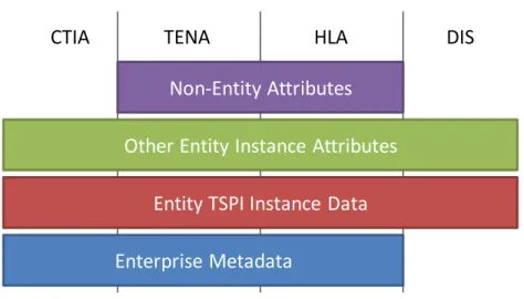
converged services, Figure 2 shows the overlaps in data used by the converged services. Enterprise metadata is shared between infrastructure elements, to convey which simulations are connected to the execution and what their publications or subscriptions cover. This data is generally not available to simulations directly, though the HLA Management Object Model (MOM) provides some access for HLA federates. All the architectures communicate Time-Space-Position Information (TSPI) describing the location and motion of each vehicle, player, or simulated entity in the execution. They also communicate other attributes of these entities, from headlights to turret positions. Both HLA and TENA support more general object models, allowing the simulation designer to define additional non-entity attributes in the execution.
Enterprise Metadata
Entity TSPI Instance Data Other Entity Instance Attributes
Non‐Entity Attributes
CTIA TENA HLA DIS
Figure 2: Legacy Architecture Data Model Overlap
The LVCAR-CT assumes that the format and common content description for multi-architecture object models will be a product of the Joint Composable Object Model (JCOM) effort. Similarly, the LVCAR Common Capabilities efforts to develop common systems engineering processes, enable reuse, and define common execution agreements are necessary precursors for adoption of converged architectures.
Three alternatives for implementing the converged services were considered:
(a) Establish a wire standard defining how all architectures would communicate the data shown in Figure 2;
(b) Establish a static Application Programmer’s Interface (API) and implementation of the converged services; and
(c) Build a shared implementation of the converged services.
Both approaches (a) and (b) add an extra layer to the existing architectures, essentially incorporating a bridge to the converged architecture within the infrastructure of the legacy architectures. The overhead, in terms of additional transformations and data wrappers, makes these approaches undesirable from a technical perspective. They also have additional support costs and architecture developers must maintain all the code needed to construct the architecture
Convergence Defining Architecture Characteristics and Activities
Page 4
infrastructure plus the code to support the converged architecture. Successful convergence would be more economical under approach (c), where the implementation of some services would be pulled out of each architecture and replaced with a shared implementation. The concept of a new wire standard was examined in the LVCAR study and found to have low return on investment. Both approaches (b) and (c) include an implementation of the converged services, and future LVCAR-CT efforts focus on defining and utilizing this implementation. This report refers to the converged services implementation as “Common Simulation Infrastructure (CSI)” and the modified part of the legacy architecture infrastructure as the “CSI Coupler” for that legacy infrastructure.
Figure 3 shows how legacy architecture infrastructures have CSI incorporated into them along a seam covered with the CSI Coupler. The programming interface to the CSI will not be a static API, but rather a modern object-oriented library implementation which provides a compromise among the legacy architectures. By taking a spiral-development approach to developing the CSI the amount of Coupler code will be minimized.
HLA Federate TENA Application RTI BGCSI Extensions . Middle . ware CSI Standard API DIS Simulation DIS PDUs . Gateway to DIS CSI Network CTIA Simulation Extensions . Middle . ware CSI Standard API
Figure 3: Common Distributed Architecture Overview
Several concepts for CSI were discussed, but the implementation decisions should be postponed to the detailed design phase. For example, the open source OpenSplice3 implementation of the Object Management Group (OMG) standard Data Distribution Service (DDS) could form the foundation for an open source CSI that is available as an OpenSplice extension.
3
Page 5
2. CONVERGED EXECUTION
The purpose of a converged execution approach is to allow the aligning of the Common Training Instrumentation Architecture (CTIA), Distributed Interactive Simulation (DIS), HLA, and TENA architectures to work together without loss of functionality. Using the selected alternative from Section 1-2, building a shared implementation of converged services, the design and implementation approach is to pull out some of the common services from of each of the architectures and replace the services with a shared implementation. Since the primary role of the architectures is to provide a conduit for communications among simulations, it will be these services that the Common Simulation Infrastructure will address.
2.1 OVERVIEW OF THE DESIGN CONCEPT
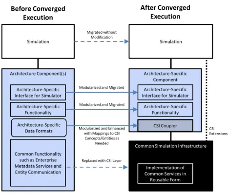
The converged execution will be realized as a migration from the current state of independent architectures, to a future state where the architectures employ one or more common components. The conceptual illustration of this migration is shown in Figure 4, using a “before and after” diagram, and the migration of code shown by the arrows in the middle. Before this migration is performed (diagram on the left), the architecture component layer is composed of, although not necessarily in a modular fashion, an architecture-specific interface with which the simulation interacts, architecture-specific functionality, architecture-specific data formats, and common architecture functionality, such as enterprise metadata services and entity communication. After the migration to a converged execution (diagram on the right), these components are modularized to allow the common functionality to be replaced with the CSI. This allows the CSI to be written in such a manner that it is architecturally independent and reusable.
This approach also reduces the footprint of the architecture-specific code, and preserves the performance of existing simulations. The CSI Coupler plays a key role in the migration. It is architecture-specific, and performs the translation and mapping between the architecture’s data structures and the common data structures used by the CSI. Over time, as new versions of the CSI and new versions of the architecture-specific components are released, a convergence on the internal data structure will naturally evolve, reducing the size of the CSI Coupler.
The CSI will provide additional interface calls that allow simulation code that has been modified to take advantage of these additional calls to query the CSI directly, using what we refer to as CSI Extensions (shown on the right side of Figure 4). The CSI Extensions will be available for simulation code that needs to directly query the CSI to obtain, for example, the multi-architecture status or to retrieve CSI activity listings. This interface will be needed for debugging, testing, and verification of proper operation of the multi-architecture. Although it allows a simulation to access the CSI directly, it is not meant to allow a simulation to skirt the use of the architecture-specific interface, and will enforce this by only allowing visibility of the CSI Extensions interface to the simulation.
Convergence Defining Architecture Characteristics and Activities
Page 6
Migration
Plan
Common Simulation Infrastructure Architecture‐Specific Component CSI Coupler Simulation Simulation Architecture Component(s) Before Converged Execution After Converged Execution Migrated without Modification
Replaced with CSI Layer Common Functionality
such as Enterprise Metadata Services and Entity Communication
Architecture‐Specific Interface for Simulator
Architecture‐Specific Interface for Simulator Modularized and Migrated
Implementation of Common Services in Reusable Form Architecture‐Specific Functionality Architecture‐Specific Functionality
Modularized and Enhanced with Mappings to CSI Concepts/Entities as
Needed Modularized and Migrated
Architecture‐Specific
Data Formats CSIExtensions
Figure 4: Conceptual Migration from Before Converged Execution to After
When combined to form a distributed simulation, as illustrated in Figure 5, the CSI performs all network communication, freeing the architecture-specific layers of code from having to perform that task. To permit this, a messaging emulation capability for the architecture-specific network communication (an architecture communicating to the same architecture, shown in the illustration as the same color architectures) is provided by the CSI.
Simulation Simulation Simulation Simulation Simulation Simulation
Architecture‐ Specific Component CSI Coupler Architecture‐ Specific Component Architecture‐ Specific Component Architecture‐ Specific Component Architecture‐ Specific Component Architecture‐ Specific Component
CSI,
Operating
at
the Multi
‐
Architecture
Level
CSI Coupler CSI Coupler CSI Coupler CSI Coupler CSI Coupler
Page 7
Figure 2 depicts the four types of data that should be communicated within the multi-architecture. To address this, the initial conceptual design for the CSI addresses these data types by providing the following services. These services are provided as examples, knowing that a future detailed interface design would rigorously detail the parameters, return values, exceptions, and callbacks, as well as verifying that the suite of functionality provided is complete enough to allow multi-architectures to fully operate.
Enterprise metadata services: example services include multi-architecture infrastructure initialization and termination, and connectivity and lifecycle status.
Entity TSPI instance services and “other entity” instance services: example services include persistent- and non-persistent-entity type creation, modification, publication, and subscription; entity creation, modification, and sending; non-persistent-entity (message) creation and sending.
Non-entity attributes services: example services include attribute publication, subscription, sending, and synchronization point services.
To show the type of proposed interactions, three examples will be explained in further detail in the following subsections: multi-architecture infrastructure lifecycle, persistent entity operations, and messaging operations.
2.2 MULTI-ARCHITECTURE INFRASTRUCTURE LIFECYCLE
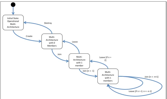
To provide a robust communications layer for a multi-architecture execution, the CSI will need to coordinate initialization, a mechanism to determine its state, and a controlled termination. The proposed set of primitive methods for the multi-architecture infrastructure lifecycle are the request for the creation of the multi-architecture infrastructure, the request to terminate the multi-architecture infrastructure, a request by the individual simulations to join the multi-architecture infrastructure, and a request by the individual simulations to leave. Figure 6 is the state diagram of the multi-architecture infrastructure lifecycle.
The Create method allows an optional parameter of naming the multi-architecture infrastructure. The Join, Leave, and Destroy methods are associated with the multi-architecture infrastructure itself. The Join method takes a name for the joining simulation as a parameter, so that other simulations can refer to it by a human-readable name. Callbacks are provided by the CSI to inform one simulation that other simulations are joining or leaving the multi-architecture infrastructure. The Destroy method will not destroy the multi-architecture infrastructure if there are any simulations that have not left the multi-architecture by calling the Leave method. Additional methods may need to be added to address the termination of rogue or run-away simulation processes that have not called Leave.
Convergence Defining Architecture Characteristics and Activities Page 8 Create Initial State: Operational Multi‐ Architecture Multi‐ Architecture with 0 Members Destroy Multi‐ Architecture with 1 member Join Leave Multi‐ Architecture with n members Join [n <‐1] Leave [if n = 2] Leave [if n > 2; n <‐n‐1] Join [n <‐n+1]
Figure 6: The Multi-Architecture Infrastructure Lifecycle
2.3 PERSISTENT ENTITY OPERATIONS
There are two basic types of entities that are communicated in a distributed multi-architecture infrastructure, persistent entities that we will refer to as “objects” and non-persistent entities, referred to as “messages.”
To maintain compatibility with most simulation architectures, objects may have the ability to be instantiated, have methods, and utilize remote method invocation. This approach is in contrast to having objects being simply a handle that is tracked for its existence. If a simulation-specific Data Exchange Model (DEM) was used as the core API simulation mechanism that identified what a simulation is capable of publishing and receiving, then “adapter” software modules would likely be developed and used that provide DEM to Architecture Neutral Data Exchange Model (ANDEM) transformation and exchange support.
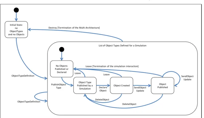
The state diagram for defining object types and instantiating and updating objects is shown in Figure 7.
Currently in most distributed simulations implementations, there is a known list of object types that will be used throughout the lifetime of the simulation. In the future, it is assumed that the creation of new object types during the running of the simulation will be used frequently, and simulations will be written with the agility to handle the processing of these new object types. For these cases, the CSI method ObjectTypeDefinition can be used, providing ANDEM definitions of object structure as a parameter, which can be converted to a Universal Data Exchange Model (UDEM) that defines the new object types. Given this information, the CSI will communicate these new object types to the other CSIs in the multi-architecture. Each CSI
Page 9
will perform callbacks to their respective CSI Coupler, allowing the CSI Coupler to determine how to address type naming issues, type conflicts, and type mapping given its architecture-specific nature.
Simulations need to indicate that they will be publishing objects of a known object type. Callbacks will notify the other simulations of this intent. Once a simulation has indicated its intent to publish, an object can be created using the DeclareObject method. This object is then sent to other simulations via a SendObjectUpdate method. To indicate to the multi-architecture infrastructure that an object is no longer needed, the simulation that owns the object calls the DeleteObject method, which informs the other simulations that the object is deleted.
ObjectTypeDefinition Initial State:
no ObjectTypes and no Objects
Destroy [Termination of the Multi‐Architecture]
PublishObject Type
List of Object Types Defined for a Simulation
No Objects Published or Declared Object Type Published by a Simulation Object Created Declare Object Object Published SendObject Update Leave [Termination of the simulation interaction]
DeleteObject Leave Leave DeleteObject SendObject Update ObjectTypeDefinition
Figure 7: Lifecycle of Object Types and Objects
A method, ReserveObjectName, allows an object name to be formally recognized. Once called, the multi-architecture infrastructure is notified that an object name is to play a unique role within the multi-architecture infrastructure.
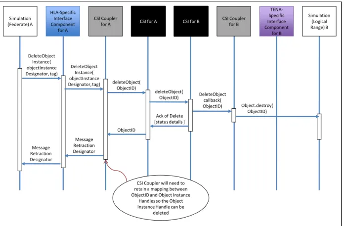
An example of the sequence of activities for an object is shown in Figure 8, illustrating the deletion of an object by a HLA Federate, which is processed by a TENA Logical Range that is subscribed to the object type. The CSI Coupler for simulation A converts the HLA DeleteObjectInstance call to the CSI DeleteObject call, and the appropriate communication to the remainder of the multi-architecture is performed. Since Logical Range B did not own the object, it only needs to be notified that the object has been deleted, which is passed from its CSI Coupler to the Logical Range.
Convergence Defining Architecture Characteristics and Activities Page 10 DeleteObject Instance( objectInstance Designator, tag) DeleteObject Instance( objectInstance
Designator, tag) deleteObject( ObjectID) deleteObject( ObjectID) Ack of Delete [status details ] ObjectID Message Retraction Designator Message Retraction Designator DeleteObject callback( ObjectID) Object.destroy( ObjectID)
CSI Coupler will need to retain a mapping between ObjectID and Object Instance
Handles so the Object Instance Handle can be
deleted HLA‐Specific Interface Component for A CSI Coupler for A TENA‐ Specific Interface Component for B CSI Coupler for B CSI for A CSI for B
Simulation (Logical Range) B Simulation
(Federate) A
Figure 8: Sequence Diagram for Multi-Architecture Object Deletion
2.4 MESSAGING OPERATIONS
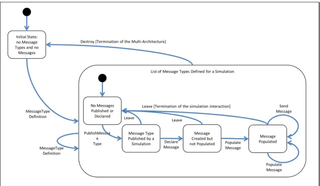
The state diagram (Figure 9) regarding message types and messages is very similar to that of object types and objects (Figure 7), except that messages do not have persistence, and therefore, cannot be updated over time. After a message type is defined, the message type can be indicated as published by a simulation, and subsequently a message can be created using a DeclareMessage method associated with that message type. Messages do not have pre-defined content, so the message can be populated using a PopulateMessage method, and subsequently sent to other simulations using a SendMessage method. A simulation can reuse a message by either re-populating it and/or re-sending it. Since a message is not persistent within the multi-architecture infrastructure, there is no need to indicate destruction of it.
Page 11 MessageType Definition Initial State: no Message Types and no Messages
Destroy [Termination of the Multi‐Architecture]
PublishMessag e Type
List of Message Types Defined for a Simulation
No Messages Published or Declared Message Type Published by a Simulation Message Created but not Populated Declare Message Send Message Leave [Termination of the simulation interaction]
Leave Message Populated Populate Message Leave Populate Message MessageType Definition
Figure 9: Lifecycle of Message Types and Messages
An example of the sequence of activities for a message is shown in Figure 10, illustrating the sending of a message by a TENA Logical Range B, resulting in a HLA callback to HLA Federate A that is subscribed to the message type. The CSI Coupler for Logical Range B converts the TENA-triggered method to the CSI CreateMessage call, followed by a PopulateMessage, followed by a SendMessage call, and the appropriate communication to the remainder of the multi-architecture execution is performed. In this case, the SendMessage results in an HLA ReceiveInteraction callback to Federate A.
Convergence Defining Architecture Characteristics and Activities Page 12 StealthFighter. MissileAway() StealthFighter. MissileAway.
ChangeTrigger() createMessage(messageType ToCreate) MessageHandle Populate Message( Message, AttributeList) Send Message( Message) Send Message( Message) Receive Message callback( Message) Receive Interaction callback( InteractionClass Designator, ValuePairs, tag) Receive Interaction callback( InteractionClass Designator, ValuePairs, tag) HLA‐Specific Interface Component for A CSI Coupler for A TENA‐ Specific Interface Component for B CSI Coupler
for B CSI for B CSI for A Simulation
(Logical
Range) B
Simulation
(Federate) A
Page 13
3. CONVERGENCE ACTIVITIES
This section describes the activities necessary to get from the current architecture implementations to the recommended converged approach.
3.1 CONVERGENCE SYSTEMS ENGINEERING
The convergence approach shown in Figure 4 depends on a systems engineering process that displaces functionality from the legacy architecture infrastructures into the CSI. Pursuing a spiral development approach to this displacement minimizes the risk exposure while providing incremental deliverables. These systems engineering activities will involve reusable software engineering expertise and detailed technical knowledge of the legacy architecture implementations.
3.1.1 CSE Requirements and Risk Analysis
The state and sequence diagrams from Section 2 will be completed during the LVCAR-CT effort for all the use cases developed by the LVCAR-LVCAR-CT. This baseline technical approach will provide a reference for spiral development of a requirements specification for the converged approach. The requirements will be mapped to the available reusable software with unrestricted rights and the resulting designs evaluated for technical risk. CSI implementation priorities will be set to retire the risks as quickly as possible.
3.1.2 CSE Enterprise Metadata Communication
The internal enterprise metadata shown in Figure 2 must be communicated through the CSI before simulation data paths can be established. Initial integration and checkout of the CSI implementation and Coupler prototypes can be conducted using this information.
3.1.3 CSE Prototype Evaluation
Evaluation criteria must be set as the CSI implementation proceeds and test results from Coupler prototypes are available. The assessment of this software demonstrates that the implementation risks have been addressed and may indicate new areas for implementation.
3.2 COMMON TRAINING INSTRUMENTATION ARCHITECTURE (CTIA)
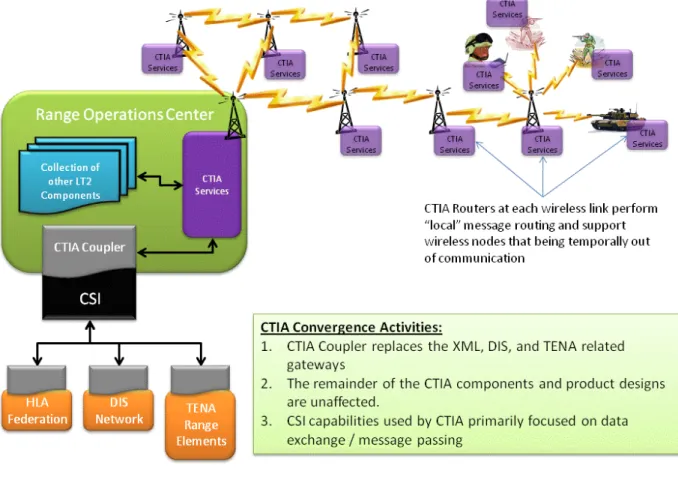
CTIA is based on a Service-Oriented Architecture (SOA). Live Training Transformation (LT2) components within the CTIA framework interact with services via defined Interfaces [defined using the Common Object Request Broker Architecture (CORBA) Interface Definition Language (IDL)]. The components use these CTIA services to mediate their interaction with one another through the CTIA framework. As shown in Figure 11, the integration approach for converging CTIA is centralized at the Range Operations Center. Responsibility for these activities should be with the CTIA Architects in order to maintain close integration with the rest of the CTIA solution.
Convergence Defining Architecture Characteristics and Activities
Page 14
Figure 11: CTIA Convergence Focused on Central Range Operations Center
3.2.1 CTIA Execution Interfaces
The CTIA notion of an execution does not expose the Join and Connect services needed by the Coupler. CTIA must associate the CSI execution name with a CTIA exercise and represent multi-architecture objects within the CTIA database. The architects need to create a CTIA-to-CSI gateway component that provides an interface between the multi-architecture objects of the CSI and internal CTIA messages to support creating a converged exercise. The CTIA-to-CSI coupler component provides a translation between the CSI functionality and the existing CTIA Services IDL. If changes to the CTIA Services IDL are required, the architects can use the CTIA Architecture Working Group (AWG) forum to request the change.
The architects also need to create a CTIA-to-CSI coupler that provides an interface between the multi-architecture objects of the CSI and internal CTIA messages to support destroying a converged exercise. The CTIA-to-CSI coupler provides a translation between the CSI functionality and the existing CTIA Services IDL. If changes to the CTIA Services IDL are required, the architects can use the CTIA AWG forum to request the change.
The architects also need to create a CTIA-to-CSI coupler that provides an interface between the multi-architecture objects of the CSI and internal CTIA messages to support creating a message instance to be sent to another object within the converged exercise. The
Page 15
CTIA-to-CSI coupler provides a translation between the CSI functionality and the existing CTIA Services IDL. If changes to the CTIA Services IDL are required, the architects can use the CTIA AWG forum to request the change.
3.2.2 CTIA Interactions
The message constructs of CTIA are defined by the CTIA data model. Some extension to support general object models could be made. The architects need to create a CTIA-to-ANDEM transform that provides an interface between the ANDEM objects and CTIA Object Model. The CTIA-to-ANDEM transform provides a mapping between the ANDEM objects and the existing CTIA Object Model. If changes to the CTIA Object Model are required, the architects can use the CTIA AWG forum to request the change.
The architects also need to create a CTIA-to-CSI coupler that provides an interface that allows the objects used within the CTIA data model to be declared as objects within the converged federation LVC exercise. The CTIA-to-CSI coupler provides a translation between the CSI functionality and the existing CTIA Services IDL. If changes to the CTIA Services IDL are required, the architects can use the CTIA AWG forum to request the change.
3.2.3 CTIA Transfer of Ownership
The CTIA notion of ownership is static. Support for ownership transfers has been done on a case-by-case basis to support live player rest periods. CTIA needs to: (1) add capability to transfer "ownership" between live player and simulation; and (2) allow attribute update from an external source. The architects need to perform a functional thread analysis to articulate one or more use case scenarios that describe the conditions under which transfer of object ownership would occur. Each use case scenario can be decomposed to identify the: (1) user interaction with the system; (2) interactions between components; (3) expected capabilities (i.e., inputs, outputs, functions, and constraints); (4) sequence diagram details; (5) description of the data elements to be exchanged; and (6) relevant system design decisions and associated decision rationale. Once the thread analysis is complete, the architects should create a more detailed plan for implemented the ownership transfer capability within CTIA in coordination with the CTIA AWG.
3.3 DISTRIBUTED INTERACTIVE SIMULATION (DIS)
DIS uses a wire protocol, standardized in IEEE study 1278.1 [Reference (b)] and IEEE study 1278.1a [Reference (c)] that allows interoperability between real-time simulations of weapons platforms. DIS is a network protocol with hundreds of implementations. Therefore, it is unreasonable that every implementation would be expected to be redesigned to use the CSI, as is hoped for the standard implementations of other architectures. As shown in Figure 3, DIS will require an additional Gateway computer to host the CSI and Coupler for DIS. The responsibility for DIS convergence must be shared between the DIS advocate and the LVCAR Common Gateways and Bridges (LVCAR-CGB) team.
Convergence Defining Architecture Characteristics and Activities
Page 16
3.3.1 DIS to CSI Gateway
The general function of the Gateway is a standard DIS interface adapted to run in conjunction with the CSI interface, translating each DIS Protocol Data Unit (PDU) to a CSI update and vice versa. Stateful PDUs translate to entity/object updates and transient PDUs translate to interactions. The Gateway performs network socket operations on the DIS side to send and receive DIS PDUs. It also performs Endian conversion and keeps an internal database of entities and objects so that heartbeat and dead reckoning can be properly accomplished. The bulk of the code is the actual translation between DIS PDU format and the Data Exchange Model used by the CSI for every attribute and parameter.
3.3.2 DIS Gateway Requirements
The DIS/CSI Gateway software needs to support DIS network communication using both broadcast and multicast user datagram protocol datagrams. Multiple simultaneous multicast groups are used.
The DIS/CSI Gateway needs to translate between a single DIS exercise and a single CSI multi-architecture execution. Multiple exercises/federations can be handled by running multiple instances of the Gateway.
The Gateway transmits DIS PDUs at their proper heartbeat rates between updates. Entities and objects time out if no PDUs are received in the proper timeout period. Dead reckoning is performed on Entities as specified by the DIS standard. The heartbeat, timeout, and dead reckoning parameters need to be configurable.
3.4 HIGH LEVEL ARCHITECTURE (HLA)
There are several versions of the HLA architecture. The first, referred to simply as HLA 1.3, was sponsored by the United States (US) DoD Modeling and Simulation Coordination Office (formerly, Defense Modeling and Simulation Office). A subsequent version, often referred to simply as 1516 [References (d), (e), (f), and (g)], is an Institute of Electrical and Electronics Engineers (IEEE)-approved refinement to the original HLA specification. In like manner, a new HLA standard called, colloquially, 1516 Evolved is in the final IEEE approval process. HLA uses a marketplace with multiple vendors who implement and sell Run-Time Infrastructure (RTI) software. While participation by all RTI developers in the CSI activity is possible, particularly where an open-source paradigm can be employed, only market forces can assure that all RTIs will become compatible with CSI. As a result, there may be a more lengthy migration period until full convergence benefits can be achieved. The possibility also exists that users may change which RTI they use in order to interoperate through CSI.
3.4.1 HLA Convergence Assessment
Extending support to HLA for multi-architecture interoperability should be a fairly straight-forward evolutionary step. Consider that if each federate was engineered to work as described by its Simulation Object Model (SOM), whereby the SOM is used to declare the
Page 17
federate’s simulation data exchange capabilities, then it would be fairly straight-forward to map various Federation Object Models (FOMs) used for federation participation to a federate’s SOM. However, the reality is that this flexibility is not commonplace for HLA federations. The majority of HLA Federates are built to work with a FOM (not a SOM). Because the exchange capabilities of a federate are often built with a FOM in mind, not a SOM, the refactoring and recompilation of the federate is often needed for any new FOM (or RTI) to which it must adhere.
The bottom line is that most HLA federates are designed to work with one FOM, one version of the HLA standard, and one RTI. However, as described by the IEEE 1516 HLA [References (b) and (c)] standard, it is possible to support concurrent federation executions. This means more than one FOM may exist and be used among many federates, but again, most federates are limited to support just one. If one couples these limitations with the need for HLA federates to participate in exercises that may consist of simulations supporting other architectures including TENA, DIS, CTIA, or other variants of HLA, the breadth of limitations that need to be overcome are apparent.
It is through CSI that principles such as the CSI coupler concept described previously for SOM-based HLA federates can be utilized. A CSI coupler module would allow a FOM-oriented federate to more quickly adapt to support other types of FOMs. This would also facilitate multi-FOM participation, which has always been an intended capability of HLA. Furthermore, a CSI coupler module could help eliminate RTI vendor dependence for federation executions allowing large numbers of federates to interoperate. It is through CSI that federates adhering to different HLA variants and simulations adhering to other interoperability standards can interoperate cooperatively without requiring major modifications (i.e., refactoring and recompilation), or large laden gateways.
3.4.2 HLA RTI Implementation
The need will exist for RTIs to utilize additional code that supports the adaptation of FOMs to what is anticipated to be a Universal Data Exchange Model, which reflects the data exchanged through CSI. The FOM to UDEM adaptation is identified as a transform module, located within the CSI Coupler.
The anticipation is that RTI vendors could help develop the necessary CSI Coupler software, which exploits and leverages its RTI, for their customers. Additionally, because of the FOM to UDEM transform modules that are anticipated, it will likely be necessary for RTI vendors to provide a means for their customers to integrate either stock or custom Transform Modules and allow their customers to recompile a Coupler with their integrated RTI library.
3.4.2 HLA Multi-Architecture Testing
The HLA community will require testing to demonstrate that competing RTI vendors’ products can interoperate through CSI. The effectiveness of this communication and the ability
Convergence Defining Architecture Characteristics and Activities
Page 18
to bridge both vendor difference and HLA Specification differences will be essential to widespread adoption.
3.5 TEST AND TRAINING ENABLING ARCHITECTURE (TENA)
The computational metaphor of TENA is different from the protocol-based DIS or more service-oriented architectures of CTIA or HLA. TENA’s Domain-Specific Software Architecture is a specification of the common software building blocks of a domain, based on a set of objects that model that domain that leads to a pool of reusable, interoperable, composable applications. It is through calls on objects within this framework that a simulation is constructed and executed. Convergence activities will involve changes to the TENA middleware as well as automatic code generated for Proxy and Servant objects used in the TENA architecture (see Figure 12).
TENA Middleware
TENA Application C
User
Application
Code
Servant
Proxy
Proxy
Servant
Proxy
Figure 12: In Addition to Middleware, the TENA Architecture includes Servant and Proxy Objects Generated Automatically by TENA Tools
3.5.1 TENA Enterprise Metadata
The TENA data model includes parts of the execution data used by CSI. Additions will be required to include execution information such as simulation application names. No significant or structural changes are expected.
3.5.2 TENA Additional Features
The converged services of Section 1.2 are not all currently supported in TENA. Synchronization Points and Simulation Timestamps would have to be added to TENA middleware. Current TENA simulations, which do not use these features, would not need to be
Page 19
changed. Changes to use these features would be made when a TENA simulation is utilized in a multi-architecture event.
3.5.3 TENA Ownership Transfer
The ownership transfer approach possibilities for TENA require ongoing investigation. TENA objects are atomic, and object attributes could only be transferred as a complete set. New TENA mechanisms to allow a Servant object to be seamlessly replaced by a Proxy object would be required. At the least, all the automatically generated code for a simulation would have to be rebuilt, but other changes might be necessary to enable and control such transfers.
Convergence Defining Architecture Characteristics and Activities
Page 20
4. COURSES OF ACTION
This report does not contain the courses of action. Courses of action will be defined by scheduling these activities as a function of time and available resources. The Final Convergence Report will present multiple courses of action and a recommendation for the best way to move convergence forward.
A high-level plan would consist of developing the other use cases. While each use case is examined the LVCAR-CT will create state and sequence diagrams of the use cases in order to understand which functionality belongs to the CSI, which to the coupler and which remains within the legacy architecture. Draft requirement specifications will be developed for each. Once detailed design artifacts are completed, each use case and corresponding design will be evaluated for risks and risk mitigation plans will be created. Priorities will be set in order to inform the spiral development. After acceptability criteria are established for the spiral, prototypes will be implemented, tested and evaluated to inform future design changes.
To inform the above high-level plan of action, a logical sequence for examining use cases can be developed. Lifecycle functionality including multi-architecture infrastructure initialization (create), status, and termination (destroy) followed by joining and leaving should occur first. It is here that CTIA would expose join, destroy, and connect services. TENA would provide middleware changes that create extensions to related execution data. DIS would implement its Endian translations.
Next, non-persistent message passing could be examined. At this stage, each legacy architecture would develop type declaration translations to the UDEM as well as publications and subscriptions messages. Publishing simulations would populate messages and send them through their couples to the CSI and onward to the subscribed simulations. DIS would implement required functionality to handle heartbeats and timeouts. TENA would investigate auto-code generation changes required.
The next phase would examine persistent objects. These use cases involve entity-type creation, entity creation, modification, and updating. The subsequent phases would include transfer of ownership, synchronization points, time management and other advanced features.
Page 21
5. SUMMARY
The LVCAR-CT has established an independent view of the current architectures. The next step is to determine what actions lead to convergence. The vision is that in 2015 new versions of CTIA, DIS, HLA, and TENA will come out that will incorporate the results of the Convergence Initiative. These new versions will continue to provide their users with services that maintain the value of previous investments in LVC software applications. However, as a result of collaboration between architecture engineering teams and limited additional changes, the new versions can much more easily and effectively be bridged.
The LVCAR-CT work does not stand alone. In particular, many preconditions, which are being pursued as part of related tasks, are necessary to achieve this vision. The LVCAR-CT assumes the following efforts will be successfully accomplished on schedule and actively collaborates with the teams involved to encourage such success:
1. The LVC Systems Engineering process defines common processes for distributed simulation development, widely disseminates them, and enables work on process overlays for multi-architecture events.
2. The JCOM produces an architecture-independent data-exchange model representation compatible with all architectures.
3. The LVC Common Capabilities activity defines a reuse solution (registry, repository, etc.) compatible with all the architectures.
4. The LVC Bridges and Gateways activity identifies mechanisms to convert between the legacy versions of the architectures.
5. Management can effectively incentivize action by architecture proponents.
Building on these results, a convergence concept has been developed with agreement from the SMEs of each of the legacy architectures. Activities have been documented which would achieve convergence in line with this timeframe.
Convergence Defining Architecture Characteristics and Activities
Page 22
Page A-1
APPENDIX A: REFERENCES
(a) Saunders, R. et. al., “Legacy Architectures Reference Model,” Johns Hopkins University Applied Physics Laboratory, November 2009.
(b) Distributed Interactive Simulation Committee of the IEEE Computer Society, “IEEE Standard for Distributed Interactive Simulation – Application Protocols,” IEEE Std
1278.1-1995.
(c) Distributed Interactive Simulation Committee of the IEEE Computer Society, “IEEE Standard for Distributed Interactive Simulation – Application Protocols,” IEEE Std
1278.1a-1998, 19 March 1998.
(d) IEEE FEDEP Working Group, “Federation Development and Execution Process (FEDEP),” IEEE Recommended Practice 1516.3-2000. R. R. Lutz, editor, April 2003. (e) Simulation Interoperability Standards Committee, “Standard for Modeling and
Simulation High Level Architecture - Federate Interface Specification,” IEEE Std IEEE
1516.1-2000. HLA Working Group, March 9, 2001.
(f) Simulation Interoperability Standards Committee, “Standard for Modeling and
Simulation High Level Architecture - Framework and Rules,” IEEE Std IEEE 1516-2000. HLA Working Group, December 11, 2000.
(g) Simulation Interoperability Standards Committee, “Standard for Modeling and
Simulation High Level Architecture - Object Model Template Specification,” IEEE Std
Convergence Defining Architecture Characteristics and Activities Appendix A: References
Page A-2
Page B-1
APPENDIX B: ABBREVIATONS AND ACRONYMS
ANDEM Architecture Neutral Data Exchange Model
API Application Programmer’s Interface ASTMP Army Science and Technology Master Plan
AWG Architecture Working Group
CORBA Common Object Request Broker Architecture CSI Common Simulation Infrastructure
CTIA Common Training Instrumentation Architecture DDS Data Distribution Service
DEM Data Exchange Model
DIS Distributed Interactive Simulation DoD Department of Defense
DSEEP Distributed Simulation Engineering and Execution Process FEDEP Federation Development and Execution Process
FOM Federation Object Model HLA High Level Architecture IDL Interface Definition Language
IEEE Institute of Electrical and Electronics Engineers JCOM Joint Composable Object Model
JFCOM Joint Forces Command LT2 Live Training Transformation LVC Live, Virtual, and Constructive
LVCAR Live-Virtual-Constructive Architecture Roadmap LVCAR-CGB LVCAR Common Gateways and Bridges
LVCAR-CT LVCAR Convergence Team
MOM Management Object Model
OMG Object Management Group PDU Protocol Data Unit
PEO STRI Program Executive Office for Simulation, Training, and Instrumentation (US Army)
Convergence Defining Architecture Characteristics and Activities Appendix B: Abbreviations and Acronyms
Page B-2 SME Subject Matter Expert
SOA Service-Oriented Architecture SOM Simulation Object Model
TENA Test and Training Enabling Architecture
TSPI Time-Space-Position Information UDEM Universal Data Exchange Model
US United States
NATIONAL
SECURITY ANALYSIS DEPARTMENT
THE JOHNS HOPKINS UNIVERSITY APPLIED PHYSICS LABORATORY
Johns Hopkins Road, Laurel, Maryland 20723‐6099