Li, Heng, Chan, Neo K.Y., Huang, Ting, Skitmore, Martin, & Yang, Jay (2012) Virtual prototyping for planning bridge construction. Automation in Construction,27, pp. 1-10.
This file was downloaded from: http://eprints.qut.edu.au/52924/
c
Copyright 2012 Elsevier B.V.
This is the author’s version of a work that was accepted for publica-tion in Automapublica-tion in Construcpublica-tion. Changes resulting from the publish-ing process, such as peer review, editpublish-ing, corrections, structural format-ting, and other quality control mechanisms may not be reflected in this document. Changes may have been made to this work since it was submitted for publication. A definitive version was subsequently pub-lished in Automation in Construction, [VOL: 27, (November 2012)] DOI: 10.1016/j.autcon.2012.04.009
Notice: Changes introduced as a result of publishing processes such as copy-editing and formatting may not be reflected in this document. For a definitive version of this work, please refer to the published source:
Virtual prototyping for planning bridge construction
Heng Li1, Neo KY Chan1, Ting Huang1, Martin Skitmore2 and Jay Yang2 1
Department of Building and Real Estate The Hong Kong Polytechnic University Hong Kong
2
School of Civil Engineering and Built Environment Queensland University of Technology
Gardens Point Brisbane Q4001 Australia
Corresponding author
Martin Skitmore MSc PhD FRICS MCIOB
Professor of Construction Economics and Management School of Civil Engineering and Built Environment Queensland University of Technology
Gardens Point Brisbane Queensland Q4001 Australia Email: [email protected] Tel: +61 7 3138 1059 Fax: +61 7 3138 1170 7 April 2012 (Version 4)
Virtual prototyping for planning bridge construction
Abstract
4D simulation, building information modeling, virtual construction, computer simulation and virtual prototyping are emerging topics in the building construction industry. These techniques relate not only to the buildings themselves, but can also apply to other forms of construction, including bridges. Since bridge construction is a complex process involving multiple types of plant and equipment, applying such virtual methods benefits the understanding of all parties in construction practice.
This paper describes the relationship between temporary platforms, plant and
equipment resources and a proposed-built model in the construction planning and use of Virtual Prototyping Simulation (VPS) to implement different construction scenarios in order to help planners identify an optimal construction plan. A case study demonstrates the use of VPS integrated with temporary platform design and plant and equipment-resource allocation to generate different construction scenarios.
Subject headings
Planning, bridges
Key words
Virtual prototyping, plant and equipment-resource allocation, temporary platforms, construction plant and equipment, bridges.
1. Introduction
The planning of construction work is the first and crucial step of a successful project and from which all other tasks or activities follow. Planning is an arduous, complex and time-consuming task. Even experienced construction planners find it impossible to build/design a comprehensive and faultless master construction plan at the first attempt, so that reviews and updates are always necessary. The amount of cost and time involved in reviewing and updating, however, can be wasteful. Ideally, it would be best to develop the final construction plan at the first attempt.
Compared with building construction projects, bridge and highway construction involves fewer activities and crew. However, the degree of complexity in constructing a bridge or highway is similar to that of buildings. In addition, the construction of bridge and highway projects of any magnitude has become increasingly difficult due to the highly competitive environment and complexity of the management process involved (Shah 2008). Bridge construction entails complex geometric configurations that render the communication of project information among interested parties very difficult and prone to errors (Liapi 2003). Applying innovative techniques to bridge construction projects for construction planning and scheduling, therefore, has the potential to assist project planners in making decisions that are more appropriate.
For bridge and highway construction, approaches already exist that attempt to optimize construction plans. For example, El-Rayes (2001) and Hassanein and Moselhi (2004) have developed an object-oriented model for planning and scheduling highway construction; El-Rayes and Kandil (2005) also created a multi-objective genetic algorithm using a three-dimensional time-cost-quality trade-off analysis to identify
optimal resource utilization plans, and Said et al. (2009) apply computer simulation to optimize the planning of bridge construction and associated resources involved. In addition, Kamat and Martinez (2003) use a visualization system, VITASCOPE, to produce a 3D animation of plant and equipment operations according to a set of geometric transformations of pieces of plant and equipment generated by discrete-event simulation. Discrete-event simulation is a powerful method to test the performance or investigate the potential problems of real-world systems, helping determine reasonable allocation policies. CYCLONE (Halpin and Riggs 1992) uses only a small set of modeling elements and provides a convenient tool for the study of various construction operations. The developed "offspring" of CYCLONE is STROBOSCOPE (Martinez and Ioannou 1994), which is a simulation programming language designed for the specific modeling and simulation of construction operations. Zhang et al (2004) used an object-oriented approach, including the object-oriented modeling concept and object-oriented programming mechanisms to develop an activity object-oriented simulation strategy for modeling construction operations. However, it is obvious that activity location, working area of plant and site layout considerations is essential for construction planning. Insufficient workspace available on site results in productivity loss, potential safety hazards and poor-quality work (Riley and Sanvido 1995).
Much research in recent years has focused on simulating and visualizing construction plans to reduce the time and problems involved. For example, 4D simulation (Koo and Fischer 2000; Wang et al 2004; McKinney and Fischer 1998; Dawood et al 2002; Hu et al 2008), computer simulation (Kamat and Martinez 2001; Kamat and Martinez 2007), virtual construction (Waly and Thabet 2002; Clayton et al 2002) and virtual prototyping (Huang et al 2007; Baldwin et al 2009; Li et al 2008, 2009) are all able to contribute to minimizing these problems.
Liapi (2003) has applied 4D CAD to actual bridge and highway projects to provide a better understanding of the aspects and spatial constraints involved compared with the traditional 2D format. Similarly, Zhou and Wang (2009) use 4D simulation for bridge construction to provide the user with a forecast of construction schedule and resource consumption over time. Park et al. (2009) also apply 3D CAD to test construction plans and scenarios for improving the constructability of the bridge construction, while Kim et al. (2011) have developed 4D CAD at three different levels of detail: activity, discrete operation, and continuous operation, for analyzing and modeling bridge construction.
The emerging technologies may look similar. However, there are significant differences between 4D CAD and computer simulation in the level of detail in project control. 4D CAD is initiated at the project level for product modeling whilst computer simulation focuses on the operational level for operation modeling (Kamat and Martinez 2003). Even when 4D CAD is applied (Liapi 2003), no existing model can optimize construction plans by allowing for potential collisions between construction plant and equipment and space conflict among activities. VITASOPE (Kamat and Martinez 2007) and virtual prototyping (Li et al 2009), on the other hand, are effective tools to avoid such collisions at the operational level related to the dynamic motion of resources (e.g. crews, equipment and materials). Meanwhile Virtual Prototyping (Li et al 2009) is useful in helping to simulate various construction methodologies at the project level relating to building components constructed over time. The virtual prototyping platform is developed through a 4D space technique to optimize construction planning to solve the critical shortcomings of discrete-event simulation. Project and operational levels are inextricably linked and the effective analysis of the feasibility of construction plans is needed by considering both the project and operational levels simultaneously.
The aim of the research described in this paper was to develop a virtual prototyping simulation (VPS) approach for simulating different construction scenarios in order to help planners identify optimal construction plans. The paper first describes the characteristics of bridge projects to identify the critical issues involved. The next section describes the application of the VPS approach to bridge construction. A case study then demonstrates the use of VPS for improving construction plans. Finally, future improvements to the VPS technology are identified and discussed.
2. The characteristics of bridge projects
Bridge construction involves multiple recurring activities, such as building foundations, piers and decks (El-Rayes 2001) - processes that are comparatively straightforward in comparison with building projects. While constructing bridges involves less working activities than building construction, it does not necessarily follow that bridge construction is an easy task. Problems and uncertainties are always likely to occur during the working process. Some factors are especially critical, including 1) the relationship between the terrain and proposed bridge and 2) the various designs of temporary work such as temporary platforms, 3) determining the number of resources, 4) the cost of the project and 5) the duration of the project.
A bridge project is a continuous linear project (Hassanein and Moselhi 2004; Platt 2007), characterized by a geometrically linear layout and no clearly identifiable units. Highway and bridge projects involve an intensive period of earthworks and the topography often changes with the filling and cutting work involved. While building construction projects contain discrete time-linked objects such as columns and slabs
(Platt 2007), clearly identifying and linking with discrete schedule activities is not possible.
In contrast with building projects, many bridges and highways are constructed on a sloped working area (earthwork) such as mountains or hills. As building projects are often carried out on plane surfaces, excavation is made to level surfaces. In bridge projects, excavation is minimized, as it is both costly and environmentally unfriendly, which leads to the challenge of designing economical and efficient working platforms to achieve the maximum productivity of overall construction plans.
3. The approach of virtual prototyping simulation (vps)
Virtual prototyping comprises the construction and testing of a virtual prototype or digital mock-up involving a realistic computer simulation of the life cycle of a physical product for presenting, analyzing and testing (Dai and Göbel 1994; Wang 2002). In addition, simulation addresses the broad issues of physical layout, operational concept, functional specifications, and dynamics analysis under various operating environments (Xiang et al 2004; Drews and Weyrich 1997). For example, by simulating separate events, manufacturers can evaluate the effects on material flow, throughput and utilization of a product under different scheduling and product mix conditions to understand the performance of the design in several manufacturing situations (Brown 2004). Some researchers also apply this technology to simulate the processes involved in building construction projects (Huang et al 2007).
Kamat and Martinez (2003) recognize the project and operational levels as two distinct levels of detail of the visualization and models of construction processes. At the project level, construction progress is visualized as a set of building components
constructed over a period of time. At the operation level, on the other hand, the dynamic motion of resources (e.g., crews, pieces of equipment, and materials) used during operations are visualized.
While the project and operation levels put different elements into perspective, a more comprehensive approach to analyzing the feasibility of the construction plans effectively is to consider both levels simultaneously. To do this, a VPS system was developed by customizing an existing third-party solution, DELMIA, currently in use in the manufacturing industry. DELMIA is a product of Dassault Systemes and is one of the most powerful VP applications used in manufacturing. The core of DELMIA is a product, process and resources model that links with various applications such as 3D model design, process planning, resources planning, discrete and continuous event simulation, 3D visualization, layout planning and virtual reality, all in the same platform. The DELMIA V5 environment uses Visual Basic for Applications (VBA) and Microsoft Project to develop construction plans with the 3D Model. VBA is an object-oriented programming language to develop specific functions and provides a seamless link between the components of the model supported by a powerful graphical user interface (GUI).
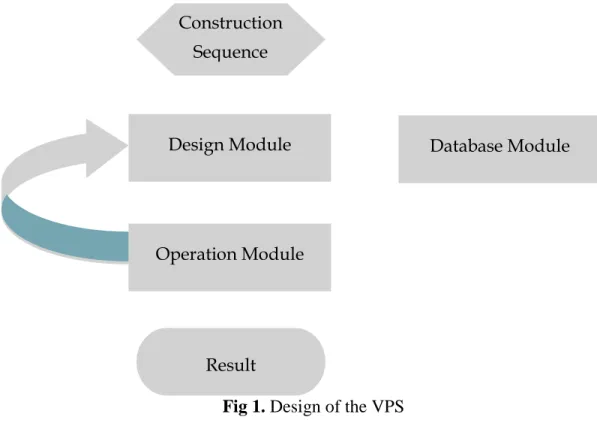
The research objective was to develop a tool to analyze the feasibility of different scenarios of construction plans. Validation is the core activity of the VPS system, which consists of three modules: the Design, Database and Operation Modules (Fig 1). The design of a 3D model and allocation of resources in construction plans relies on the Design Module. The Database Module is a data system providing information such as
resource models and constraints for the design module. The Operation Module is a program system for simulating the final-design output for reporting the results.
3.1 Prototype of construction sequence
The prototype of construction sequence is the foundational logic of activity and the sequence cannot be changed. One example is Pier Construction (i.e. Pipe Cap Excavation -> Pipe Cap Concreting -> Pier Construction -> Pier Head Construction). Different construction planning arrangements can then be developed according to the prototype of construction sequence.
3.2 Proposed-built model
The proposed-built model is built from a 3D CAD system (i.e. CATIA) which provides the 3D CAD components. Generally, 3D CAD systems currently available on the market do not have built-in functions that allow this kind of information integration. 3.3 Construction equipment model
The deployment of construction plant and equipment is one of the critical items involved in the design / plan of construction plans. The definition of the construction equipment model is an enhanced plant and equipment-based model linked with the productivity of plant and equipment in an Excel library database and with physical capacity data (Li et al 2009) for use in construction planning and construction simulation. The specifications of the construction plant and equipment are embedded in this 3D-geometry model. This includes the actual 3D-geometry, turning and working radius, lifting capacity, etc, of the plant and equipment involved. The construction equipment model simulates real-life working processes (e.g., the crane lifts the steel from the storage area
to the final position for installation). If the plan is not constructible in reality (e.g. there is not enough workspace for driving or not enough distance from the target), the VPS technology highlights these problems based on the specification data and virtual environment. Furthermore, the VPS technology can detect a potential collision course between the plant and equipment involved.
3.4 Database of construction plant and equipment
Building a database is an efficient approach to store and capture all types of information concerning the construction plant and equipment models and their productivity data. All of the productivity data come from another similar construction project in a period of two weeks in order to compute useful productivity data for virtual prototyping use. In this way, the virtual platform simulates the plant and equipment operations to test for any collisions. All the construction plant and equipment models are built and stored in the VPS library installed in the system for future planning use. Different types of plant and equipment are grouped into different categories and different types of activities are classified into different categories (Table 1). Therefore, the project planners can use their experience to assign suitable plant and equipment models and allocate plant and equipment to carry out designated activities for the analysis of various construction scenarios.
3.5 Plant and equipment-resource allocation
In previous research, the resources involved are space, plant and equipment and crew. However, the crew is not a critical factor of the construction planning of bridges as the total number of the crew needed is fewer than that for building projects. The allocation of plant and equipment is the most critical item affecting the cost and construction duration.
In the system, plant and equipment-resource allocation is one of the variable factors in the planning process. The plant and equipment amount can be adjusted and the duration of each task is generated by computing the amount and type of plant and equipment and their associated productivity. Different construction scenarios are considered by examining different temporary work designs to allocate different plant and equipment when simulating the construction process. Such variables, including different types of plant and equipment and resource amounts, generate varying results and durations relating to the construction planning process.
3.6 Temporary work design (i.e. temporary platforms)
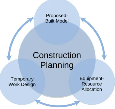
Owing to the fact that bridge construction involves a limited working area and in accident-prone site conditions, the design of temporary work (i.e. temporary platforms) is a critical factor affecting construction plans. The proposed-built model, construction plant and equipment and temporary work design are the three key influencing factors involved. At the same time, these three factors or variables have a significant effect on each other (Fig.2). Designed and built into the design module are the relationships and constraints among the proposed-built model, construction plant and equipment and temporary work designs.
Building construction projects apply parametric 3D modeling worldwide (Huang et al 2007; Slaughter and Eraso 1997; Sacks et al 2004). Huang et al (2007), for instance, apply this form of modeling to temporary work elements and Sacks et al. (2004) use a parametric 3D model to design precast concrete. These models are based on operations and constraints, with constraints maintained as an integral part of the model geometry during editing.
The temporary work design originates from the parametric 3D modeling approach and the design of our parametric 3D model is based on fundamental constraints, user requirements and safety issues. The model provides a user-friendly platform for sketching and modifying the basic 2D design. This is very important as, if the user changes the equipment or fundamental constraints, the 3D model changes directly. It can also save a lot time for modeling. Temporary work design has its own design components that are affected by the specification, amount and logistical arrangement of the plant and equipment as well the location and size of the proposed-built model.
3.7 Collision detection
Collision detection is an essential component for construction planning, where it helps to analyze the physical clashes that occur between the 3D elements. There are two types of collision detection, namely those that occur between: 1) static objects and. dynamic objects (e.g. moving plant and equipment and railings); and 2) dynamic objects (e.g. the activities of an adjacent excavator and crane).
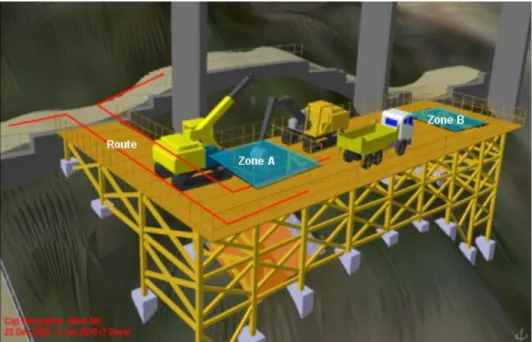
Collision occurrences relate to the space of the route and construction plans. For example, whether a route is large enough for more than two pieces of equipment to pass through is a key factor affecting the design of the activities. Collisions can occur when ordering three machines to work in Zone A while three other machines work in Zone B if the size of the route is not large enough for the pieces of equipment to pass through (Fig. 3). These activities are highlighted in the VPS as a geometric contact when they are about to occur or have actually occurred. The result is generated in the form of data, including the activity time and the name of the two elements involved in the collision.
3.8 Possible results
The possible results of a construction scenario are as follows:
1) Feasibility result (the construction scenario is feasible if a collision is not detected, otherwise it is infeasible). As a result, the following clash reports may be generated a. For a collision detected between a static object and a dynamic object, a clash
report is generated providing details of the proposed model or temporary work design, occurrence time and capture of the virtual occurrence
b. For a collision detected between a dynamic object and another dynamic object, a clash report is generated providing details of the associated activity tasks, occurrence time and a capture of the virtual occurrence.
2) A comprehensive construction plan including the design of temporary platforms and plant and equipment-resource allocation
3) The quantity of steel needed for the temporary platforms 4) The duration of the construction plan
5) Visualization of the construction process simulation. 3.9 Framework of the VPS
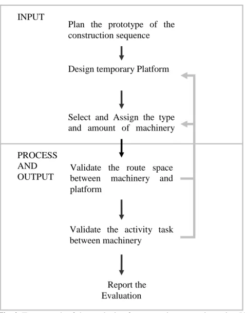
Fig.4 illustrates the framework for applying the VPS and comprises six steps:
Step 1: Planning the prototype of construction sequence of the task, including the start-end times of all activities such as concreting, pouring, fixing rebar etc.
Step 2: Designing the temporary platform under the constraints set by the proposed-built model
Step 3: Selecting and assigning the type and amount of plant and equipment needed, based on the nature of each activity
Step 4: Validating the route and working platform to establish that there is enough working area between the selected plant and equipment and the working environment (if it fails, go back to step 2 or 3)
Step 5: Validating of the activity clashes between plant and equipment (if it fails, go back to step 2 or 3)
Step 6: Generation of the results.
4. Case Study
4.1 Introduction
The case study involved the widening of a section of the Ting Kau Viaduct, which is a part of the Tuen Mun Road, a road link between Tuen Mun and Kowloon, Hong Kong. The road is 15 km long and has been in service for more than 30 years, having a long history of traffic congestion and accidents. It was designed and constructed in the mid-1970s and needed to be raised to current standards as far as practicable. In addition, road was planned to be reconstructing with a minimize repair works, traffic congestion and accidents, and therefore create less disturbance for road users.
The main scope of the work included widening sections of the existing carriageways and vehicular bridges and highway structures, including Tsing Lung Tau Bridge, Telford Bridge, Ting Kau Viaduct and Yau Kom Tau Bridge. The work also included widening the eastern end of Sham Tseng Viaduct eastbound carriageway to meet current expressway standards, with the associated provision of hard shoulders and verges.
The work in widening the section of Ting Kau Viaduct included the construction of viaduct foundations, piers, deck and finishes. Ting Kau Viaduct is to be supported by
numerous piers on a hillside and twenty-eight new piers were required for the widening of Tuen Mun road. The work involved a complex site topography, localized site formation work, foundation, superstructure and stitching work to the existing road network.
The project planners encountered several types of problems relating to construction planning and constructability, including potential risks to road users in the construction area, and a number of key concerns were incorporated at this stage, including site safety, site access, temporary work design, cranes and equipment deployment. A central issue for the project planners concerned the working platform to be used in the construction process. This involved choosing one of three different working platform designs. However, the choice was not easy, due to:
• Difficulties in imagining the site environment.
• Difficulties in determining the best platform for foundation and pier construction. • Difficulties in estimating the maximum number of resources for each of the
different platform designs.
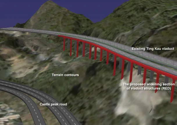
4.2 Building the virtual terrain contours, existing viaduct and proposed widening of viaduct structures
To increase the precision of the results, the research team obtained topographical survey data of the project site from the land surveyors involved. This included building the terrain contours and details of the existing Tin Kau Viaduct into a 3D model. The 3D virtual terrain contours provided a clear and detailed view for the project planners, allowing them to visualize the relationship between the terrain contours and existing viaduct and to predict safety issues and potential accidents during construction. The
proposed widening of the viaduct structure was modeled to include geometric configurations after construction, based on the 2D drawings (Fig. 5).
4.3 Construction planning
Construction planning involved temporary work design and resource allocation. Through the constraints with the proposed-built model, the precision and reliability of the temporary work design were increased. The project planner assigned and allocated different amounts of construction plant and equipment into the three different working platform designs. The different feasible construction planning processes were simulated according to the construction sequence, as shown in Table 2.
4.4 Construction scenarios for temporary work design
The choice of platform design involved two main considerations:
• The haul road - an access road from Castle Peak Road to the construction site for access of construction plant and equipment.
• The platform itself.
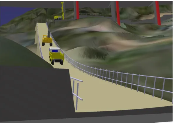
4.4.1 The haul road
Most of the critical construction work was under the existing viaduct and on the hillside. However, the hillside was not a suitable platform for workers and construction plant and equipment and a haul road provided a means for transporting the construction plant and equipment from Castle Peak Road to the proposed construction site (Fig. 6). The essential requirements of the haul road were that the slope was less than 1:10 and with a minimum width of 5m.
4.4.2 The platform
The function of the steel platform was to provide a working space from which the construction equipment could drive pilings. This would have made it difficult for the project planner to confirm a platform design because of its importance to the success of the project. Using the parametric 3D model however, the design of the steel platform could be drawn or modified easily and quickly. The platform safety designs remained fixed throughout the modeling process, and the railings of the platform were generated automatically in each of the three model designs produced by the research team. Modeling the haul road and the platform took approximately forty person-days.
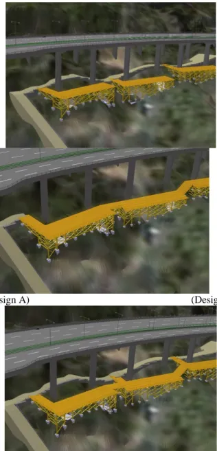
Fig. 7 shows the three different designs of steel platform. These comprised:
Design A - Each platform overlapped two piers, with the entrance connected to the haul road.
Design B - Each platform fully overlapped all piers but with only one entrance connected to the haul road.
Design C - Each platform was similar to that of design B but each pair of piers provided one entrance connected to the haul road.
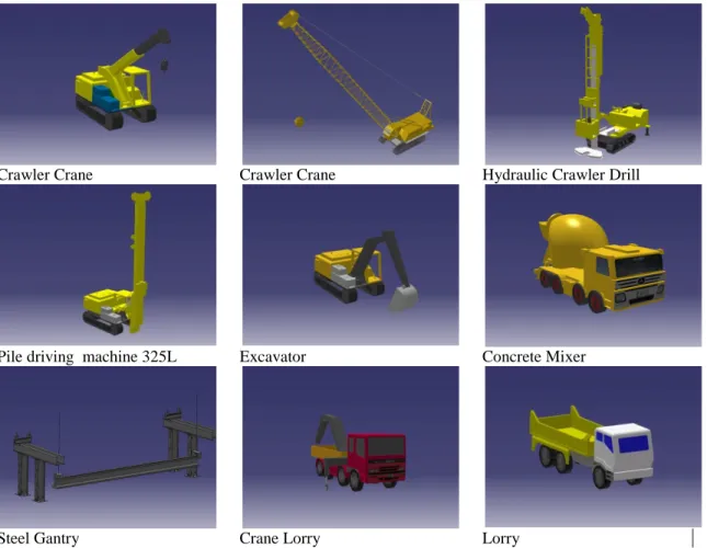
4.5 Database of construction plant and equipment
The major models of construction plant and equipment for the bridge works (Fig.8) were built in detail, including the external dimensions, working radii, moving and working space requirements and lifting capacity. For example, a 3D model of a crawler crane was developed that included its external dimensions based on the specifications, degrees of low and high limit of turning radius, rear-end swing and working radius (Fig. 9). The various lifting capacities were based on the length of working radius. Modeling
all the construction plant and equipment was a time-consuming process involving approximately 160 person-days spent on creating a single model and embedded specifications. It should be noted, however, that, once built, the models of all the construction plant and equipment involved would be available for future reuse if needed. 4.6 Allocation of construction plant and equipment model
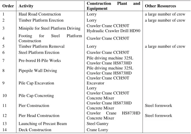
The construction plant and equipment model was selected and assigned to different activities in the construction sequence (Table 3) based on the constraints of the proposed-built model. Eight types of construction plant and equipment and two types of platforms were involved. For example, the construction plant for the pier construction was only a single Crawler Crane HS873HD as one of the constraints defined that a crawler crane should be able to lift temporary steel formwork for pier concreting. The user can assign varying amounts of construction plant and equipment to the three platform designs. Based on different designs and different resource allocations, the system simulated the construction plan.
4.7 Collision analysis
The first and second collision analyses of construction plan in the VPS were to detect and highlight any potential collisions between the construction plant and equipment and the virtual environment, such as the railings of the platform and haul road, in the simulation and between the activities of construction plant and equipment respectively. The clash report covers the associated activities and models together with the occurrence time involved.
4.8 Overall results
In design A, the system identified the clashes between the crawler crane HS873HD and existing viaduct as the crawler crane HS873HD could not be driven from one platform to the next due to the limitations in height space. Some parts of the crawler crane had to be dismantled and reassembled after the crawler crane was driven to the next platform, a process that would take 30 days in practice. Other construction equipment did not have such problems.
In design B, there was one access road for transportation. Therefore, the piers would have to be constructed one by one.. Hence, one construction machine was the maximum number allocated. The reassembly time of the crawler crane HS873HD in design A could be eliminated, as the crawler crane did not need to pass along the haul road from one platform to another. Therefore, the planner tried to enlarge the platform size to make sufficient room for two-way transportation. The results of the quantity of different steel platforms were of significant importance.
In design C, each platform was connected to the haul road and the next steel platform. The crawler crane could move across the connection between the two steel platforms. Once again, dismantling and reassembly of the crawler crane HS873HD could be eliminated. This design was ultimately found to provide the best transportation model for the construction plant and equipment.
Realistic graphical simulations (Fig. 9) were generated for visualization through the VPS and validated by the construction planners, as some activities could not be easily visualized any other way. The planners and engineers needed to spent some time studying the visualization to identify unvisualized activities. The professionals also
discussed the simulation together to enable the most benefit to be made of the VPS technique. The quantity of the steel needed for making different platforms, the amount of construction plant and equipment and the project duration were generated for planners to investigate different scenarios and then select the optimal construction plan. The planners then used the data to generate and discuss other analyses.
5. Contributions and limitations of the VPS
The critical issue in construction planning for bridge or highway construction is the nature of the design of temporary platforms. As the case study shows, the VPS, in conjunction with the practical experience of project planners, can be useful in testing the feasibility of the platforms. The contributions of the VPS include:
1) analyzing the allocation of plant and equipment-resources to prevent planning mistakes between working platform design, amounts of plant and equipment and start-finish times of activities
2) speeding up the planning time with the use of the plant and equipment-resource database
3) providing the quantity of the materials involved in the temporary works 4) generating the duration of the construction plan
5) helping project planners select a construction scenario by testing different alternatives. The main limitation of the VPS is that modeling construction plant and equipment is very time-consuming. The model took two people 3 months to build. In order to make an efficient contribution, a comprehensive database of the plant and equipment needs to be available. Another limitation of the use of VPS in bridge planning is that it falls short of identifying the optimal construction plan, as this needs the project duration to be taken
into account in addition to the cost of the working platform and equipment. Nevertheless, a shorter duration does not necessarily imply a better construction plan. For instance, although the VPS system can analyze different construction scenarios relating to the working platform and equipment, it overlooks the arrangement of the workers. For the sake of social responsibility, the construction plan needs to allow different types of workers (i.e. formwork, concreting, fixing rebar) to work every day.
6. Conclusion
One use of VPS in the construction process is to assist project planners to better understand the relationships among temporary platforms, plant and equipment resources and proposed-built models in construction planning. This paper described how the design of a 3D model and the allocation of resources could be utilized by VPS in support of construction planning. The case study demonstrated an application in which the VPS system enabled the user to validate the design of working platforms by allocating different resources. This shows that the VPS system can be used for such a purpose and can simulate construction scenarios to avoid any collisions between construction plant and equipment and construction elements. It can also help the project planners identify the optimal construction plan. Feedback from project planners indicate that a fully automated platform design process is desirable, opening the way for research into the further use of VPS for project planning.
Baldwin, A., Li, H., Huang, T., Kong, C.W., Guo, H.L., Chan, N., and Wong, J. (2009) “Supporting pre-tender construction planning with virtual prototyping,” Engineering, Construction and Architectural Management, 16(2), 150-161.
Brown, J. (2004) “The PLM Approach to Better Manufacturing Processes,” Digital Manufacturing, Tech-Clarity, Inc.
Clayton, M.J., Warden, R.B. and Parker, T.W. (2002) “Virtual construction of architecture using 3D CAD and simulation,” Automation in Construction, 11(2), 227–235.
Dai, F., and Göbel, M. (1994) “Virtual Prototyping – An Approach Using VR-technique,” Proceedings of the 1994 ASME Computers in Engineering Conference, Minneapolis, MN, 1994.
Dawood, N., Sriprasert, E., Mallasi, Z., and Hobbs, B. (2002), “Development of an integrated information resource base for 4D/VR construction processes simulation, “Automation in Construction, 12, 123-131.
Drews, P., and Weyrich, M., (1997) “A system for digital mock-up’s and virtual prototype design in industry: the virtual workbench,” IEEE International Symposium on Industrial Electronics, 3, 1292–1296.
El-Rayes, K. (2001), “Object-oriented model for repetitive construction scheduling,” Journal of Construction Engineering and Management, 127(30), 199-205.
El-Rayes, K., and Kandil, A. (2005), “Time-cost-quality trade-off analysis for highway construction,” Journal of Construction Engineering and Management, 131(4), 477-486.
Halpin, D.W., and Riggs, L.S. (1992). Planning and analysis of construction operations, New York: John Wiley & Sons, Inc.
Hassanein, A., and Moselhi, O. (2004), “Planning and scheduling highway construction,” Journal of Construction Engineering and Management, 130(5), 638-446.
Hu, Z., Zhang, J., and Deng, Z. (2008) “Construction process simulation and safety analysis based on building information model and 4D technology,” Tsinghua Science & Technology, 13(S1), 26-272.
Huang, T., Kong, C.W., Guo, H.L., Baldwin, A., and Li, H. (2007), “A virtual prototyping system for construction processes,” Automation in Construction, 16, 576-585.
Kamat, V.R., and Martinez, J.C. (2001), “Visualizing simulated construction operations in 3D,” Journal of Computing in Civil Engineering, 15, 329–337.
Kamat, V.R., and Martinez, J.C. (2003), “Automated generation of dynamic, operations level virtual construction scenarios,” Electronic Journal of Information Technology in Construction (ITcon), 8, 65–84.
Kamat, V.R., and Martinez, J.C. (2007), “Interactive Collision Detection in Three-Dimensional Visualizations of Simulated Construction Operations,” Engineering with Computers, 23(2), 79-91.
Kim, C., Kim, H., Park, T., and Kim, M.K. (2011), “Applicability of 4D CAD in Civil Engineering Construction: Case Study of a Cable-Stayed Bridge Project,” Journal of Computing in Civil Engineering, 25(1), 98-107.
Koo, B., and Fischer, M. (2000), “Feasibility study of 4D CAD in commercial construction,” Journal of Construction Engineering and Management, 126(4), 251-260.
Li, H., Chan, N., Huang, T., Guo, H.L., Lu, W., and Skitmore, R.M. (2009), “Optimizing construction planning schedules by virtual prototyping enabled resource analysis resource analysis,” Automation in Construction, 18(7), 912-918.
Li, H., Huang, T., Kong, C.W., Guo, H.L., Baldwin, A., Chan, N., and Wong, J. (2008), “Integrating design and construction through virtual prototyping,” Automation in Construction, 17(8), 915-922.
Liapi, K.A. (2003), “4D visualization of highway construction projects,” Proceedings of the 7th International Conference on Information Visualization (IV’03), 1093– 9547/03.
Martinez, J., and Ioannou, P.G. (1994), “General purpose simulation with stroboscope.” Proceedings of the 1994 Winter Simulation Conference, 1159-66.
McKinney, K., and Fischer, M. (1998), “Generating, evaluating and visualizing Construction Schedules with 4D CAD Tools,” Automation in Construction, 7(6), 433-437.
Park, T., Kim, M.K., Kim, C. and Kim, H. (2009), “Interactive 3D CAD for Effective Derrick Crane Operation in a Cable-Stayed Bridge Construction,” Journal of Construction Engineering and Management, 135(11),
Platt, A. (2007), “4D CAD for highway construction projects,” Technical report no. 54, Computer integrated construction research program, Pennsylvania State University, PA.
Riley, D.R., and Sanvido, V.E. (1995), “Patterns of construction-space use in multistory buildings,” Journal of Construction Engineering and Management, ASCE, 121(4), 464-473.
Sacks, R., Eastman, C.M., and Lee, G. (2004), “Parametric 3D modeling in building construction with examples from precast concrete,” Automation in Construction, 13(3), 291-312.
Said, H., Marzouk, M., and El-Said, M. (2009), “Application of computer simulation to bridge deck construction: Case study,” Automation in Construction, 18(4), 377-385. Shah, R.K., Dawood, N., and Castro, S. (2008), “Automatic generation of progress
profiles for earthwork operations using 4D visualization model,” ITcon, 13, 491-506.
Slaughter, S.E., and Eraso, M. (1997) “Simulation of structural steel erection to assess innovations”, IEEE Transactions on Engineering Management, 44(2), 196–207. Waly, A.F., and Thabet, W.Y. (2002), “A virtual construction environment for
preconstruction planning,” Automation in Construction, 12(2), 39-154.
Wang, G.G. (2002) “Definition and review of virtual prototyping,” Journal of Computing and Information Science in Engineering, 2(3), 232-236.
Xiang, W., Fok, S.C., and Thimm, G. (2004), “Agent-based composable simulation for virtual prototyping of fluid power system,” Computers in Industry, 54, 237–251. Zhang, H., and Li, H. (2004), “Simulation-based optimization for dynamic resource
Zhang, H., Tam C.M., and Li, H. (2005), “Activity Object-Oriented simulation strategy for modeling construction operations.” Journal of Computing in Civil Engineering, ASCE, 19(3), 313-322.
Zhou, C., and Wan, W. (2009), “Highway bridge construction process simulation base on 4D visualization,” Proceedings of the GeoHunan International Conference.
List of Tables and Figures
List of Tables
Table 1. Plant and equipment categories for different activities Table 2. The duration of each activity for one pair of piers
Table 3. Different construction plant and equipment assigned in different activities List of Figures
Fig. 1. Design of the VPS
Fig. 2. The relationships among proposed-built model, temporary work design and equipment resource in construction planning
Fig. 3. Representation of the construction situation
Fig. 4. Framework of the analysis of construction scenarios using VPS
Fig. 5. Virtual terrain contours, existing viaduct, Castle Peak Road and the proposed widened section of viaduct
Fig. 6. The haul road from Castle Peak road to the construction site Fig. 7. Three different scenarios of steel platform
Fig. 8. The major models of construction plant and equipment Fig. 9. Crawler crane CCH50T with embedded specification Fig. 10. Snapshots of the construction simulation
Activities Plant/Equipment Plant/Equipment Models Concreting Tower / Crawler CCH50T, HS873HD,
HS855HD, HS841D Excavating Excavator A316, A900
Lifting Tower / Crawler CCH50T, HS873HD, HS855HD, HS841D
Pilling Piling Machine Hydraulic Crawler Drill HD90 Hydraulic Crawler Drill HD180 Pile machine BSP355T
Pile machine 325L Table 1. Plant and equipment categories for different activities
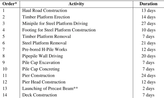
Order* Activity Duration
1 Haul Road Construction 13 days
2 Timber Platform Erection 14 days
3 Minipile for Steel Platform Driving 27 days
4 Footing for Steel Platform Construction 10 days
5 Timber Platform Removal 7 days
6 Steel Platform Removal 21 days
7 Pre-bored H-Pile Works 12 days
8 Pipepile Wall Driving 20 days
9 Pile Cap Excavation 7 days
10 Pile Cap Concreting 7 days
11 Pier Construction 24 days
12 Pier Head Construction 12 days
13 Launching of Precast Beam** 2 days
14 Deck Construction 7 days
* Construction sequence is set in an order from 1 to 14.
**Precast beam should be launched after two piles of head construction.
Order Activity Construction Plant and
Equipment Other Resources
1 Haul Road Construction Lorry a large number of crew
2 Timber Platform Erection Lorry a large number of crew
3 Minipile for Steel Platform Driving Crawler Crane CCH50T Hydraulic Crawler Drill HD90
4 Footing for Steel Platform
Construction Crawler Crane CCH50T
5 Timber Platform Removal Lorry a large number of crew
6 Steel Platform Erection Crawler Crane CCH50T
7 Pre-bored H-Pile Works Pile driving machine 325L
Crawler Crane HS873HD
8 Pipepile Wall Driving Pile driving machine 325L
Crawler Crane HS873HD
9 Pile Cap Excavation
Crawler Crane CCH50T Excavator
Lorry
10 Pile Cap Concreting Crawler Crane CCH50T
Concrete Mixer
11 Pier Construction Crawler Crane HS873HD
Concrete Mixer Steel formwork
12 Pier Head Construction Crawler Crane HS873HD
Concrete Mixer Steel formwork
13 Launching of Precast Beam Steel Gantry
14 Deck Construction Crane Lorry
Fig 1. Design of the VPS
Operation Module
Design Module Database Module
Construction Sequence
Fig 2. Relationships among proposed-built model, temporary work design and equipment resources in construction planning
Construction
Planning
Proposed-Built Model Temporary Work Design Equipment- Resource AllocationFig 4. Framework of the analysis of construction scenarios using VPS INPUT
PROCESS AND OUTPUT
Plan the prototype of the construction sequence
Design temporary Platform
Select and Assign the type and amount of machinery
Validate the route space between machinery and platform
Validate the activity task between machinery
Report the Evaluation
Fig 5. Virtual terrain contours, existing viaduct, Castle Peak Road and the proposed widened section of viaduct
(Design A) (Design B)
(Design C)
Crawler Crane Crawler Crane Hydraulic Crawler Drill
Pile driving machine 325L Excavator Concrete Mixer
Steel Gantry Crane Lorry Lorry
Minipile for Steel Platform Driving Pipepile Wall Driving
Pier Construction Launching of Precast Beam Fig 10. Snapshots of the construction simulation