By
Sophia M. D’Antoine
A Thesis Submitted to the Graduate Faculty of Rensselaer Polytechnic Institute
in Partial Fulfillment of the Requirements for the Degree of
MASTER OF SCIENCE
Major Subject: COMPUTER SCIENCE
Approved by the Examining Committee: Professor B¨ulent Yener, Thesis Adviser Professor Boleslaw Szymanski
Professor David Spooner
Rensselaer Polytechnic Institute Troy, New York
April 2015
Sophia M. D’Antoine All Rights Reserved
LIST OF FIGURES . . . vi
ACKNOWLEDGMENT . . . viii
ABSTRACT . . . ix
1. INTRODUCTION . . . 1
2. HARDWARE MEDIUMS IN CLOUD COMPUTING INFRASTRUCTURE . . . 4
2.1 Standard Cloud Computing Architecture . . . 4
2.2 Properties of Shared Hardware Resources Used in Side Channel Attacks 8 2.3 Analysis of Transmission and Reception Techniques used across Side Channels . . . 12
2.3.1 Central and Graphics Processing Units as a Side Channel Medium 15 2.3.2 The Cache Tiers as a Side Channel Medium . . . 17
2.3.3 The I/O, Memory and Other System Buses as a Side Channel Medium . . . 20
2.3.4 The Main Memory and the Dynamic RAM as a Side Channel Medium . . . 22
2.3.5 The Hard Disk, Including the Disk Drive and Virtual RAM as a Side Channel Medium . . . 23
2.4 Classification of Hardware Units and the Transmitting Methods Used Across . . . 24
3. MALICIOUS APPLICATIONS ACROSS THE SIDE CHANNEL MODEL 26 3.1 Characteristics of Malicious Side Channel Use . . . 27
3.2 Exfiltration Applications . . . 30
3.2.1 Continuously Active Receiver, No Transmitter . . . 30
3.2.2 Continuously Active Receiver, One Way Transmitter . . . 31
3.3 Infiltration Applications . . . 32 iii
3.4 Network Applications . . . 34
3.4.1 Continuously Active Transmitter and Receiver . . . 34
3.5 Summary of Three Architecture Models . . . 35
3.6 Summary of Channel Architecture Models . . . 36
4. FORMALIZATION OF THE HARDWARE SIDE CHANNEL MODEL . . 37
4.1 Models to Represent Hardware Side Channels . . . 37
4.2 Tuple Representing a Hardware Side Channel . . . 40
4.3 Channel Construction . . . 41
5. HARDWARE SIDE CHANNEL IMPLEMENTATION . . . 44
5.1 Out of Order Execution . . . 44
5.2 Exploiting Out of Order Execution . . . 45
5.3 Transmitting and Receiving Processes . . . 47
5.4 Construction of Seven Attacks . . . 50
5.5 Metrics . . . 53
5.5.1 Success . . . 53
5.5.2 Efficiency . . . 53
5.5.3 Detectability . . . 54
5.6 Description of Implemented Attacks and Results . . . 56
5.6.1 M1 Theft of Encryption Key . . . 56
5.6.2 M2 Active Program Identification . . . 60
5.6.3 M3 Environment Keying . . . 63
5.6.4 M4 Signal Trigger of Process . . . 66
5.6.5 M5 CPU Resource Contention . . . 69
5.6.6 M6 Determine VM Co-Location . . . 72
5.6.7 M7 Bi-Way Communication . . . 75
5.7 Summary of Implementation Measurements . . . 78
6.1 Anomaly-Based Channel Malware Detection . . . 81 6.2 Signature-Based Channel Malware Detection . . . 83 6.3 Pattern-Based Channel Malware Detection . . . 83 6.4 Inherent Strengths of Hardware Side Channels Against Detection . . 84 6.5 Potential of Detection Techniques against Side Channel Attacks . . . 86 7. CONCLUSION . . . 89 LITERATURE CITED . . . 91
2.1 The hardware organization of the xeon family multi-core processors . . 5 2.2 The differences in cache architecture between industry multi-core
pro-cessing units . . . 7 2.3 Memory hierarchy of related hardware components . . . 12 2.4 Physical resource allocation between virtual instances on a cloud server 14 2.5 Hardware component organization on a multiprocessor server . . . 17 2.6 Primary system buses and their functionality . . . 21 2.7 Mechanisms used to transmit and receive across different hardware units 25 3.1 The three permutations of the two processes used in side channel
con-structions . . . 27 4.1 A bit stream, with each time frame and its average measurement
repre-senting a single bit . . . 42 5.1 Two threads depicting possible results of the swap . . . 46 5.2 The store instructions in both receiver threads; the second move requires
a reorderable load in the processor . . . 49 5.3 A complete diagram of the different stages of a deployed attack in a live,
cloud computing environment . . . 51 5.4 The encrypted string compared to the leaked string . . . 59 5.5 The bit stream leaked through the receiver showing the repeating pattern
associated with running videos in chrome . . . 62 5.6 Use of the central processor in synced, concurrent time frames allows the
transmission of a signal between two colluding applications in real time 67 5.7 The array values before and after computation . . . 71
5.9 A botnet which uses n bots that receive commands and transmit re-sponses to the central authority; our side channel acts as the relay . . . 77 5.10 A table listing the average deploy rate for each of the seven attacks
im-plemented as well as the associated standard deviations . . . 78 5.11 A chart visualizing the execution rate of each implementation and the
minimum times necessary for each attack’s success . . . 79 6.1 The set of detection techniques applicable to the seven attack categories
deployed across the out-of-order-execution side channel . . . 82
I would like to thank Professor Yener for advising me through my master’s thesis. Jeremy Blackthorne for introducing me to this area of research. Dan Guido and Alex Sotirov from Trail of Bits for providing me technical resources.
Given the rise in popularity of cloud computing and platform-as-a-service, vulnera-bilities inherent to systems which share hardware resources will become increasingly attractive targets to malicious software authors.
This thesis first classifies the possible mediums for hardware side channel construction. Then we construct potential adversarial models associated with each. Additionally, a novel side channel is described and implemented across the central processing unit using out of order execution.
Finally, this thesis constructs seven adversarial applications, one from each adver-sarial model. These applications are deployed across a novel side channel to prove existence of each exploit. We then analyze successful detection and mitigation tech-niques of the side channel attacks.
Modern cloud computing services employ the use of shared hardware between different virtual machine instances in order to increase efficiency and decrease cost. However, when hardware resources, such as the cache [1, 2, 3], are dynamically allocated to dif-ferent virtual machine processes, a single virtual machine can continuously measure artifacts from its virtual allocation of a single hardware component and note changes it did not cause.
This allows the resident of one virtual machine instance to detect changes in the system caused by another virtual machine located on the same physical hardware. This information leakage allows an adversary to construct a side channel attack used to either record coresident behavior or communicate with a process purposefully gen-erating these system changes [3, 4].
In covert side channels, a receiving software process is used to measure information from the unintentionally accessible hardware component. In the same way, a sending, software processes, located on a different virtual machine, provides this information across the hardware resource. In this way, the privacy provided by virtually allocation is bypassed.
The first section of this thesis presents a classification of the different shared hard-ware resources which may be exploited by a virtual machine process. We attempt to organize the different characteristics of each hardware medium to acquire the trans-mitting features used in a side channel construction.
Using these features, we analyze and compare the varied aspects of side channels built across different mediums to extract successful and limiting features.
Using these shared hardware mediums, this thesis then presents seven primary mali-cious attack models which may be applied across side channels built on each outlined hardware mediums. The distinctions between each are made according to the meth-ods in which the processes attempts to attack co-resident virtual machines over a side channel, with the intent to extract or alter system information. Together, the mali-cious attack models encompass all malimali-cious channel behaviors. Under each model, specific malicious processes can be categorized.
Each adversarial model is then analyzed for its potential across different hardware side channel architectures, presenting a formalization based on the transmission and reception functions of the channel. Cross applying the set of malicious program mod-els on the set of hardware mediums, outlined in the first section, results in all pairs of attack vectors. We then analyze each pair for its applicability in real world cloud computing environments.
Finally, we implement a subset of the malicious program model, hardware medium pairs, targeting all pairs which use the central processing unit as the exploited hard-ware medium.
Using the processor, a novel side channel is constructed. Specifically, out of order execution is exploited to transmit and receive signals. We explore the use of this information as a channel through which malicious programs can operate covertly. Provided a sender,receiver, and message encoding schema we can create an effective attack vector with calculable success.
We discuss each malicious program implemented across the processor side channel in order to acquire insight into the scope of a hypothetical adversary on a cloud computing infrastructure.
INFRASTRUCTURE
Hardware side channels in cloud computing infrastructures rely on shared physical resources as the medium through which information is transferred. To do so, different variables unique to the targeted hardware component may be queried, measured or altered by the side channel processes residing on a virtual machine instance.
As the information gathered is specific to processes using the queried hardware com-ponent, a malicious virtual machine instance may only leak information from other co-resident virtual machines instantiated on the same shared hardware. Any infor-mation gained about a targeted, coresident VM may be polluted with noise caused by any number of benign coresident VM’s.
This section attempts to first detail the hardware architecture found in cloud centers, categorize the hardware mediums found in these infrastructures, and cursory explain how side channel processes use them to transmit or receive information.
2.1
Standard Cloud Computing Architecture
In the industry standard for cloud computing infrastructure, a large physical hard-ware system is virtually allocated across a multi-core platform. This virtual allocated of hardware resources increases the efficiency of large scale computation for infras-tructure as a service (Iaas).
As a result, multiple virtually allocated machines share processor time and memory space on a mutually held physical machine. For the sake of this thesis, the assumed architecture of the physical machine will belong to Intels Xeon family.
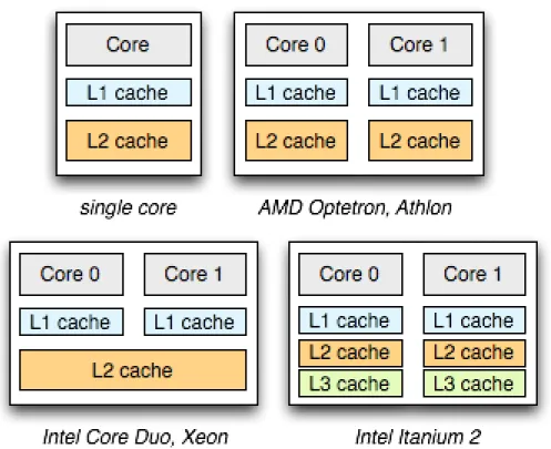
Depicted in Figure 2.1, is the physical organization of the hardware components which comprise a standard cloud computing server. Previous research done in the field of cloud security and hardware side channels have focused on this model as it best represents the largest market share for Infrastructure-as-a-Service (IaaS) [5, 6].
Figure 2.1: The hardware organization of the xeon family multi-core pro-cessors
Specifically, this hardware model includes a shared L2 cache across multiple cores and, in some units, an larger L3 cache shared across all processing units (CPUs).
In modern, multi-core systems an increased number of multi-tiered caches are added to overall reduce latencies incurred by time consuming queries to main memory. Such latencies are measurable on the order of several hundred nanoseconds. On average using this structure, for each memory access query, the processor saves time on a scale of two to three orders of magnitude.
Additionally, the multiple cores and processors allow for multi-threaded applications to be executed simultaneously. The diagrams depicted in Figure 2.2 represents how the organization of cache levels for multi-core processing units can vary across hard-ware provider; the Intel Core Duo, Xeon will be the reference point for this thesis’s discussion of security and exploitable side channels.
The Intel Core Duo, Xeon processor contains an even share of shared and unshared memory. Shared memory between processors leads to contention of cache tiers used to store data. For programs running multiple threads with algorithmically complex op-erations across multiple cores, these shared cache tiers are optimal. Programs which do not gain much efficiency from shared cache include those which run simultaneous operations on exclusive sets of data.
In cloud computing environments, each virtual machine instance of a customers ma-chine on the physical hardware unit is managed through a hypervisor. This hypervisor acts as a resource scheduler to dynamically allocate the performance equivalent of a single, full processing core (CPU) for the duration requested. This allocation may span across several cores and cache units on the same server if other co-located pro-cesses require more of a resource.
Figure 2.2: The differences in cache architecture between industry multi-core processing units
Multiple virtual machine instances allocated simultaneously are not guaranteed to be co-located on the same shared server. The notion of co-location is the primary element in the success of any hardware based, side channel attack vector [7, 4, 8]. Different hardware components of a server, applicable to side channel attacks, shared virtually and modifiable by the user, are discussed further in the section below.
2.2
Properties of Shared Hardware Resources Used in Side
Channel Attacks
The first required property for extracting information from across a cloud computing side channel is location. The third part provider must provision the computing re-sources for the malicious and targeted virtual machine on the same physical unit. The adversarial instance must reside on the same server as the target instance in order to extract target information from the hardware component. For this reason, the most thorough security protection against side channel attacks implemented over a trusted third-party cloud infrastructure is the complete physical isolation of all equipment and hardware for the guaranteed instances. This thesis assumes that there is a sin-gle, unique hypervisor on each server to dynamically divide resources between virtual machines. For attacks targeting cloud computing, the use of the Xen hypervisor du-plicates the cloud environment for all side channel research discussed below.
A product of commercial cloud infrastructures, is the randomization of virtual ma-chine placement adding an additional layer of security. There is only a percentage of chance that the target instance and the malicious instance are placed on the save physical server containing the necessary multi-core microprocessors. To construct a fully operational side channel attack, we first determine if the controlled virtual machine is co-resident with the target. If not, a new instance may be created and tested. This technique is repeated until co-residence is determined. The important function of this technique is the ability for a virtual machine to realize it has achieved co-residency.
The research done by RSA labs and University of North Carolina Chapel [7] intro-duced the HomeAlone system which allows a virtual instance to verify its exclusive residency on a physical machine. There technique may be used to determine if a virtual machine is co-residing with another and thus susceptible to a side channel attack, specifically through exploitation of the shared L2 cache.
For their defensive purposes, a virtual machine verifies that there is no foreign in-stances residing on the hardware. This machine pre-arranges for the ´friendly´ınin-stances to withhold from cache usage in a pre-determined time frame. During this time, the defensive machine measures an artifact of the shared L2 cache. Any unexpected ac-tivity divulges the presence of an unwanted resident. There are rare limitations to this model, such as an opponent which can withhold cache usage during the period of measurement. However, the general application of this technique, using a variety of heuristics, is highly effective.
Another method used to establish co-residency, a consumer is allowed to purchase a virtual instance on demand and the cloud service provider multiplexes many in-stances across shared hardware [4]. In this work, various side effects of the multiplex-ing system, such as networkmultiplex-ing speed, proximity and addresses, are exploited to verify co-residency on the same server with a high measurable accuracy. This work found that purchasing an instance immediately after the target, in the same geographical region, highly increased the probability of sharing resources.
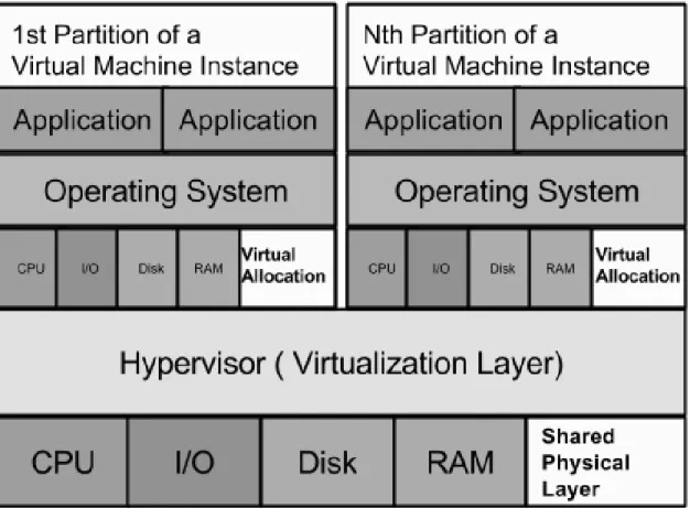
In figure 2.4, a representation can be seen of the co-residency ofn virtual instances in a cloud computing server. Also depicted is the allocation, based on client operations, of physical resources by virtualized slices of memory and processor time. The various shared and un-shared cache levels are not shown in this simplified diagram.
The consideration of these two methods does not exclude other potential methods to determine co-residency but merely highlights two broad techniques, measuring hardware and network heuristics. Once the co-location of the adversarial and the target virtual machine instances can be verified, the side channel attacks discussed in the subsequent sections can be constructed.
The second property, required for implementing a side channel across virtual ma-chines, is shared memory and cores, multiplexing. In cloud environments however this is enabled by default as it is a more profitable setup, allowing the provider to meet the unique constraints of the virtual machines computation. The Xen hypervi-sor must be set to share time-slices of the available CPUs between all virtual guest instances on the server, potentially overbooking the amount of virtual CPUs. As this is the current standard in cloud computing infrastructure, for the scope of this thesis, the Xen architectural model will be assumed.
A feature of this model is the dynamic interplay between memory retrieval, caching and instruction execution slices of the hardware components. When these resources are shared, a single instance can now dynamically affect and react to the surrounding environment; an environment which contains other virtual machine instances.
The third property required for implementing successful, virtual machine side chan-nels is that the channel activity should have a low delta from any benign user activity.
While this property is not a requirement for a functioning channel, it indicates to-wards the deployability of the side channel attack across a live cloud computing infrastructure. A successful channel will use operations that are both non-invasive
and non-unique. The invasiveness can be measured in excess resources used outside of any normal operating levels. For example, a system which conveys a message between two virtual machines by filling the entire cache would be considered highly invasive. The reality of this channel on a real system communicating without detection is im-probable in that the other co-located machines, deprived of any space in the cache, would catch the attention of the service provider. Limitations on cache use would effectively mitigate the side channel.
The ideal channel must also be non-unique. For example, a channel which relies on routinely using a certain cache address or spiking the processor’s load demonstrates behavior which is highly anonymous. The ideal channel, to avoid rapid detection and hypervisor resource access rules, uses a commonly accessed hardware medium. A component which supports more active and sporadic behavior allows the channel activity and resource accesses to become statistically insignificant.
If these three primary system properties are met for any chosen hardware component and side channel attack, then it has the potential for successfully relaying information when deployed across a real world cloud computing system.
2.3
Analysis of Transmission and Reception Techniques used
across Side Channels
Each physical component which is shared between virtual machines is potentially ex-ploitable for use in a side channel, with varying degrees of success. In order to better analyze the possibilities, we consider all hardware components of a server.
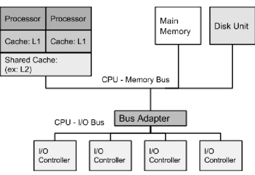
This section discusses each hardware component in order to assess what feature pro-vides the transmission and reception mechanisms. These features, specific to the medium, make up part of the side channel´s characteristics, effecting its potential. In figure 2.5, the major components of the larger computational environment are shown. These are the different units which will be referenced in this thesis as distinct trans-mitting mediums.
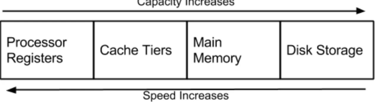
Figure 2.3 shows a standard memory hierarchy of four hardware units used in mem-ory management. They are shared between the co-residing virtual machine instances. As speed increases, capacity decreases. The majority of side channels exploit this inherent speed characteristic.
A single virtual machine measuring data retrieval times can discover on which compo-nent of the hierarchy its information is located. This capability is in fact not meant to be hidden and is legitimately used by many programs to optimize operations. How-ever, when hardware is shared, it may become a mechanism to determine location of not only personal data but also the behavior of the co-residing virtual instances.
Figure 2.4: Physical resource allocation between virtual instances on a cloud server
2.3.1 Central and Graphics Processing Units as a Side Channel Medium
One of the shared resources, used in side channel attacks, is the processors. This may include the central processing unit, the graphics processing unit, or both as long as the graphical processor is allocated for the purpose of general purpose computing.
The use of the graphics processor to increase computation speed makes its use as a potential side channel in cloud computing even more relevant. Specifically, the graphics processor unit (GPU) has a massively paralleled architecture consisting of smaller, more efficient cores designed for handling multiple tasks simultaneously mak-ing it better fit to handle high loads. Usmak-ing this processor over the central processmak-ing unit makes sense in multi-cored, parallel computing.
An information leak from the use of GPGPU (General Purpose GPU computing) is exploited to leak an AES key through research by Roma Tre University, [9], which exploits the resource managers necessary for GPGPU. The resource managers, CUDA (by NVIDIA) and OpenCL (by AMD), are used to interface with the graphics proces-sor and to direct its use for computation. These platforms generate system artifacts in speed and memory which may be leveraged as a side channel by an attacker. Specifically, the CUDA architecture provides the system with shared memory, global memory, and registers available to the executing processes. This leads to cross vir-tual machine contention of these resources, resulting in information leakage between instances.
The central processing unit has been widely researched as a vector for side chan-nel attacks in cloud infrastructure. The same methods to detect changes in system time and memory can be used for sending signals across the CPU as with the GPU.
A side channel over the central processing unit is developed in research by Prince-ton University [10] where the CPUs functional units or FUs, are exploited through a simultaneous multi-threaded process (SMT). Additionally, basic timing attacks are shown across shared processors[11] .
A single central processing unit has a set of functional units which are to be dy-namically allocated to each process running as a SMT thread every cycle. The basis of the covert channel lies in these shared functional units. One process intentionally alters its use of the functional units in predetermined time intervals in order to inter-fere with other processes. When this resource contention occurs, a malicious process is able to discern artifacts from the environment.
The implementation of this side channel relies on measured time, the time it takes for a process to be allocated the appropriate functional units. Execution time will either slow or speed up depending on the state of the allocation. This makes measured time the transmitting vector for signaling between the isolated virtual machines. A proposed security defense against this channel is a selective partitioning solution in which resource sharing is minimized, adding noise and overhead to the system.
For both the graphical and central processor, time, as an effective measurement of resource allocation, enables information leakages across shared hardware. Side Chan-nels developed using this technique are termed covert timing chanChan-nels and may be constructed across hardware mediums besides the processors.
2.3.2 The Cache Tiers as a Side Channel Medium
There are three tiers of cache common in cloud computing servers, the L1, L2, and L3, each with varied memory space and distance from the the processor. We recog-nize that Amazon cloud services now offer premium C4 instances which run on Intels latest Xeon E5-2666 v3, Haswell, processors.
This new server provides an additional fourth tier of cache memory, L4. However, for the purposes of this thesis, all specific discussion of cache will address the common architecture only including L1, L2 L3.
Figure 2.5: Hardware component organization on a multiprocessor server
As these tiers only differ in size and location, cache based side channel techniques developed against specific tiers of cache apply to all tiers with varied speeds.
In general, cache provides high speed memory access for the processing unit as an in-termediary stage before much slower memory requests to main memory are required. The different tiers are labeled according to speed, L1 being the fastest and closest to the processor, and LN being the slowest and farthest away.
L1 provides the quickest and most expensive memory access, as it uses static RAM or SRAM cells. Additionally, L1 cache tiers are tied to a single core on standard multi-core processors as can be seen in Figure 2.5.
The L2 cache tier has become private, dynamically allocated memory, focused on a single processor and its set of cores. Similar to the dynamic partitioning and archi-tecture of the L2, the L3 cache tier acts as a shared pool of memory common to all processing units on a system-on-a-chip (SoC). Higher quantities of L3 cache, and L2 cache, provide faster shared memory for virtual machines and multi-threaded (SMT) applications.
An adversary can take advantage of these shared resources through contention, mem-ory probing, or preemption in order to leak valuable system information with the intention of forming a side channel.
While L1 cache is tied to a single core, virtualized allocation of a single core be-tween processes or machine instances means the L1 cache is as well. This dynamic sharing becomes a mechanism to measure system artifacts.
Specifically, the L1 cache is vulnerable to a prime-probe technique. This was used to construct a covert timing channel to exploit the L1 cache and extract an ElGamal
decryption key from the co-resident, target virtual instance [12]. A simple program can be implemented which fills a section of the cache associated with a given offset on each page, a technique called priming. A listening, malicious virtual machine would then query this cache section of the L1 cache page, a technique called probe. The time it takes to querying the cache acts as the transmitted signal.
The addition of different methods, such as preemption of the resource scheduler, add speed and accuracy to the channel. However, for all variations of side channel methods, time remains the fundamental measuring unit of a single bit.
Constructing side channels across the L2 cache vary in technique and precision, yet they depend on a prime-probe or preemption technique and use time to distinguish system changes.
A variant on the prime-probe transmitting technique, forcing cache misses can be used by a malicious virtual instance across the L2 cache tier to leak useful environ-ment information [3].
A malicious process may exploit the translation lookaside buffer, TLB, and its limited mapping into the L2 cache. This TLB contains only a fraction of the addresses needed to decrease the speed of translating virtual addresses. Accessing all pages known to be in the L2 cache forces a TLB miss. This L2 side channel has a lower bandwidth than a comparable prime-probe channel across the L1 cache given the difference in proximity to the processor. This utilization of timed memory queries across the L2 cache is identical to timing channels across all cache tiers. The L3 cache offers shared memory pages between processors and dynamically resized virtual cache allocations. These shared memory pages creates an attack vector to record useful environment
artifacts [13].
One such constructed channel relies on pages, shared on the L3 cache tier, and suc-cessfully leaked the private key from the GnuPG implementation of RSA [13]. A malicious virtual instance flushes a line of memory from the cache hierarchy and waits a set time frame. Then the malicious process queries the line and times how long the response takes.
If the victim instance queried the line, then the attacker now knows exactly what data the victim was accessing. This channels bandwidth relies on the granularity of the chosen time frame, sacrificing accuracy for speed.
For cache tiers, L1, L2, and L3, the measurement of time, specifically memory access time, is the key reception mechanism. Optimizations of the query algorithm may increase bandwidth, but essentially they still rely on querying time or values.
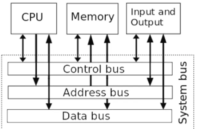
2.3.3 The I/O, Memory and Other System Buses as a Side Channel
Medium
The system buses are necessary for high speed data transfers between different mem-ory or computational units. There are several different times of buses, as can be seen below in Figure 2.6. Each bus transports different types of data via its bus line and connects the appropriate units.
Figure 2.6: Primary system buses and their functionality
These buses are required for physical communication between computing units and are shared across all virtual machine instances on the server. A side channel can be built using any of the shared buses to leak system behavior.
For example, a side channel may be constructed using memory bus contention [14]. This channel measures possible access to the memory bus as the unit to record a binary signal. To force a signal, atomic instructions from the x86 instruction set may be used, by a transmitting application, to block uncached data access through the memory bus.
Effectiveness of this channel relies on locking all processors out of an essential hard-ware component, the memory bus. This greatly increases the possibility for detection in contrast to the timing based side channel used over other transmission mediums. As many processes accessing the memory bus increase contention, the resulting chan-nel is subject to frequent interference and a great level of environment noise.
2.3.4 The Main Memory and the Dynamic RAM as a Side Channel Medium
The main memory is physically located much farther from the processors than the cache resulting in a larger access latency. However, a side channel may be developed with moderate success across different segments of the main memory.
Measurement of a pre-determined data segment in shared main memory reliably leaks environment information. The mechanism used to force contention of this shared data segment varies between specific implementations of the channel.
A side channel may be constructed to target memory paging one systems supporting SMT. Paging occurs as a result of a process requiring more memory than what is available. The system scheduler then pages these processes and corresponding data between main memory and the disk. A transmitting process can force paging by filling the main memory. A listening process can measure the shared address space allocated by the system. This measurement leaks the intentional memory use of the coresiding process which is then mapped to a binary signal.
A side channel can be implemented to exploit main memory on cloud servers, specifi-cally the dynamic random access memory or DRAM [15]. A malicious virtual process may measure a value from a memory address on the DRAM. This value may or may not be accessed immediately, leaking whether or not that specific memory address was used by another process. The success or failure of a query may then be mapped to a binary signal. In channels built across this hardware unit, memory contention is used as the transmitting mechanism.
2.3.5 The Hard Disk, Including the Disk Drive and Virtual RAM as a Side Channel Medium
Co-residing virtual instances effectively share physical hard disk space while being virtually isolated. These virtual machines effectively force or monitor hard disk space contention to transmit a signal. By measuring file read times, a process can record whether or not the file was operated on by another process and form a successful side timing channel. This method may be used for transmitting and receiving and is a variation of the prime-probe technique [4].
Added optimizations to timing channel, such as symbol and frame synchronization between processes, resulted in a one thousand times increased the bandwidth [16].
The basis of this channel relies on rapidly accessing files in a known locations on the hard disk. This forces file contention with other processes accessing them. A sim-ple side channel is constructed from this contention. A mutli-threaded, transmitting process quickly accesses a chosen set of files while the receiver tries to access them with varied read times. The physical disk drive segments, once filled, cannot be as easily re-purposed as the temporary memory units. Additionally, any disk read times will be slower inherently than read times of the other memory units as it is physically farther from the processor. These two characteristics of the disk drive results in a lower potential bandwidth.
Exploitation of any physically shared, but virtually allocated resource can lead to successfully measuring information from a computation environment. When these measured changes are caused intentionally by a co-residing virtual instance, recep-tion of a transmitted message is possible and the construcrecep-tion of a side channel.
2.4
Classification of Hardware Units and the Transmitting
Methods Used Across
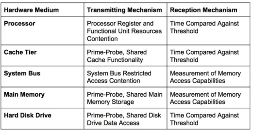
Each hardware unit’s functionality results in specific constraints specific which affect how a side channel can be constructed across it. The data, found in Figure 2.7, out-lines the mechanisms through which transmission and reception of data occurs.
The category, Transmitting Mechanism, describes a side channels technique to force a behavior in a given hardware medium. Under this category, there are two pri-mary techniques, resource contention and prime-probe. Resource contention occurs with the forced contention of a hardware units shared functionality or storage ca-pacity. When the transmitter controls a segment of a unit’s resource, the receiver may measure limited access to that resource. Prime-probe occurs when a transmitter manipulates data stored in a segment of the resource.
The category, Reception Mechanism, describes a side channels reception technique to measure behavior from a given hardware medium. Under this category, there are two primary techniques, measuring time and memory access. Measuring time to record a signal relies on an arranged time frame in which the measurement will be taken as well as an expected measurement value. This means that any noise in the system which increases latency in resource access will negatively effect the signal. Measuring memory access to record a signal has less susceptibility to system noise. A receiving process can than access this memory segment and analyze the received data.
Cloud computing server architecture shares physical resources between virtualized instances which include five major, distinct hardware units listed in Figure 2.7.
Each of these units may act as mediums across which co-resident, virtual machines construct a side channel using a transmitting and receiving mechanism to commu-nicate. Unique programming implementations of transmitting and receiving mecha-nisms may differ for each physical unit. The table in Figure 2.7 lists which mechamecha-nisms apply across different physical units.
This section provides an organization of possible side channel hardware mediums as well as fundamental transmitting and receiving mechanisms which may be applied in specific malicious applications.
Figure 2.7: Mechanisms used to transmit and receive across different
CHANNEL MODEL
With the increasing number of side channel attacks developed across the different hardware components shared in cloud environments [17, 18, 19], this section at-tempts to classify potential attacks specifically tailored to exploit these side channels. The prerequisite for any side channel is the ability to transmit and receive information by exploiting specific hardware components - such as the cache, the processors, etc. The attack models described must reduce down to a transmission and a reception mechanism.
A “transmitter” alters a exploited hardware component in a repeatable way, gen-erating an artifact which the receiver measures from the same medium. For example, to generate a signal across a cache based side channel, a transmitter may alter the data available in the cache. A “receiver” can then query a targeted location and meaningfully compared results from this query to expected ones.
This simplified model of a transmission and a reception process reduces the possi-ble set of malicious functions which could be carried out across a chosen side channel. This section focuses on categorizations for malware types contained in this possible set. While prior research will be used to exemplify the categorizations made, this section will not pursue a detailed analysis of all malware types, but only those types relevant to side channels. With a typology of malicious behaviors which exploit side channels, it is possible to further analyze documented attack vectors as well as po-tential novel attacks.
This section assumes a symmetric multiprocessing system, a modern virtual machine manager, a exploitable hardware side channel and an optimized algorithm to max-imize bandwidth across the channel. The categories described are abstracted from specific side channel implementations so as to be applicable to a larger set of processes.
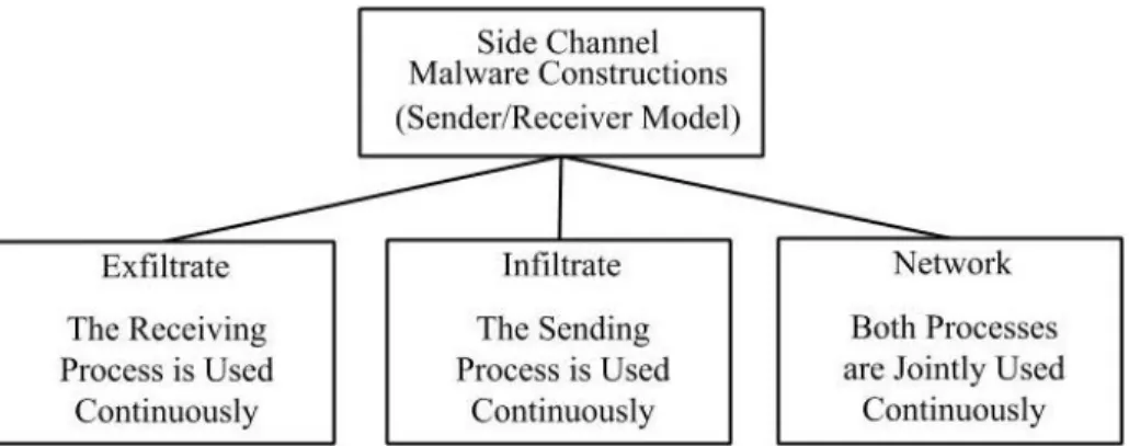
Figure 3.1: The three permutations of the two processes used in side
channel constructions
3.1
Characteristics of Malicious Side Channel Use
This section presents three classes to organize the malicious behavior which is possible across side channels. These categorizations are meant to capture all types of malicious applications, both traditional and novel, which rely on a hardware based side channel.
The “exfiltrate” and “infiltrate” categories, seen in Figure 3.1, have a distinct one way property. This means that either the sending or the receiving process of the side channel is under continual operation in the system environment. The remaining process is not the focus of the application and is either never used or used only once, independent of the surrounding system activity.
The “network” category has a bi-way property and relies on continually operating sending and receiving processes in order to effect or record system activity.
The first category, exfiltrate, refers to malicious applications which are constructed with the intent of exfiltrating system data or information. Processes in this cate-gory rely on the receiving process, where information is received through reaction to changes in the environment. Continuous operation of these reactive applications allow the adversary to effectively record the system changes over a given time period. When there is no transmitting process running, the receiving processes is reacting only to the artifacts of the targeted co-resident processes.
This record of shared hardware activity over a targeted medium can be mapped to known patterns, exfiltrating co-resident operations and information. For example, a coresident virtual machine running encryption operations will require cache resources in a pattern mappable to the encryption operations. The co-resident, receiving pro-cess setup to operate over a cache based side channel will react in a pattern similar to those of the victims encryption and can subsequently exfiltrate the encryption key [3, 20].
This category also encompasses malicious application functions which include a minor role for a transmission process. In these situations, the transmitter pre-agrees on a time frame with the receiver and is co-resident. The transmitter affects the hardware medium, creating an artifact so that the receiver can record a unique, coordinated signal. However, as the transmitter has no method of noting system responses, it cannot adjust its broadcast. This gives a one time property to the transmitting pro-cess.
The infiltrate category contains applications in which the main operating process is the transmitter and not the receiver. These applications continually transmit ac-tivity or data into the shared hardware. The effects of these operations are then seen in the reactions that the non-colluding, targeted virtual machines have in response to the altered environment.
This category also encompasses malicious application functions which include a mi-nor role for a receiving process. The reception process operates once and without any knowledge before or after of the transmitter. One example of a side channel attack, used to determine if one malicious virtual machine is colocated with another, relies on a continual transmitter and a one way receiver [4, 7].
The third category, network, jointly operates both the reception and transmission processes continuously. A common example of a malicious application modeled in this way is the construction of a communication channel. Two colluding, co-residing virtual machines can covertly communicate to one another. Each of the communi-cant applications have both a transmission and reception function which operate in a known time frame. This joint sender-transmitter programs may either affect the environment to convey a message or react to the environment to receive a message [14].
These three main categories shown in figure 3.1 attempt to organize the different primitives from which an adversary may model a malicious side channel applications. The distinctions between each category are based on different combinations of trans-mitting, receiving behavior. These distinctions ultimately determine the possible functionality of the malicious application.
3.2
Exfiltration Applications
The ”exfiltrate” category encompasses side channel applications which leak system information. Malicious programs exhibiting exfiltration behavior continually operate a receiving process. In some cases a transmission process is used once to meaningfully alter the state of the shared hardware.
3.2.1 Continuously Active Receiver, No Transmitter
A hardware side channel application which contains a continuously active reception process, and no transmitter, will react to the changes in the targeted hardware com-ponent that it exploits. Exfiltration applications record system state over time. This record of system information may be analyzed to understand the activity or state of the coresident virtual machine. A set of common malicious application types which may utilize this single reception structure is presented.
Cryptographic key theft is the most common application documented in literature and targets a hardware side channel using a single reception process. Malicious pro-grams of this type use a receiver to record the changes in the targeted hardware component, most popularly hardware cache. Patterns recorded may be mapped to known patterns which result from different encryption operations, such as multi-plication, to leak information about the key. Accounting for noise in the recorded pattern increases the likelihood of successfully retrieving a cryptographic key [21, 12].
Activity logging refers to the monitoring and recording of co-residing virtual ma-chine behavior. A specific demonstration of this type of malicious functionality is keylogging [22]. When built across a side channel, the receiving process acquires
artifacts from the user activity in the coresident virtual machines.
Pre-acquired measurements of the affects a particular user activity has to the tar-geted medium allow the recording adversary to exfiltrate sensitive information about user behavior, such as keystrokes.
Malicious applications using a continuous receiver may also employ environmental keying across a side channel [4, 7]. Comparison between an expected record with the actual record of measurements taken from the targeted hardware environment, allows the malicious application to key the virtual machine’s allocated hardware and decide how to execute. Environmental keying has many uses, such as enabling hardware specific execution, avoiding emulation or other security programs which by running on the same hardware, change the measurements taken from the environment.
3.2.2 Continuously Active Receiver, One Way Transmitter
A transmitting process is added to the receiving application model presented above. The addition of this transmitter, located in a coresident, colluding virtual machine, provides the functionality in the attack model to broadcast a signal through a shared hardware component. The receiver reads this pre-arranged signal and decides to take actions accordingly. As the transmitter cannot receive information from the system, it cannot adjust its transmission in response to external factors. We present a ma-licious application type which uses this single receiver, one way transmitter structure.
A transmitting application may act as a trigger for a receiving application through transmitting a broadcast signal by altering information on a shared hardware medium. The signal must be unique so that other, coresident applications may not generate processes which benignly alter the hardware medium in the same pattern. A receiving
processes located on a colluding virtual machine will continuously record information from the targeted component until it receives this prearranged signal. After the trig-gering pattern is received, the application can then launch additional functions, such as process initialization or masking to dynamically avoid detection or hide intended information.
3.3
Infiltration Applications
The “infiltrate” category encompasses side channel applications which cause activity in or inject data into the targeted hardware component. Malicious programs exhibit-ing infiltration behavior continually operate a transmittexhibit-ing process. In some cases a reception process is used once to meaningfully alter the state of the shared hardware.
3.3.1 Continuously Active Transmitter, No Receiver
A hardware side channel application which uses a continuously active transmission process, and no transmitter will generate disturbances in the targeted hardware com-ponent. This application will influence how the system allocates resources between coresident virtual machines as well as what data is queriable from different hardware components, affecting the performance of the coresident processes. Depending on the function of the malicious application, the injected information may be tailored to target specific performance changes.
“Hardware denial of service” refers to the performance impact that the malicious transmitting process causes in the shared hardware component. Applications in this category use a transmitter to alter the data stored in a hardware component or to force prioritization [9, 10]. The specific function of the transmitting application may rely
on a specific pattern of operations or data injected into the hardware medium, either to exploit the scheduling algorithm or to overwrite specific data stored in temporary memory. Accounting for noise caused by coresident operations and prioritization algorithms used by the scheduler increases the likelihood of successfully modifying performance of coresident processes.
3.3.2 Continuously Active Transmitter, One Way Receiver
In this category, a one time receiving process is added to the malicious application model which relies on a continuous transmission process. The addition of this receiver, located in a coresident, colluding virtual machine, provides a reception functionality in the attack model. The transmitter beacons continuously, leaving an artifact in a tar-geted hardware medium which may be read by the reception process. As the receiving process has no method for sending a response, it may only read the continuous signal from the system in the time frame that the transmitter is active. We present a ma-licious application type which uses this single transmitter, one way receiver structure.
This transmission and reception model may be exploited to determine virtual ma-chine colocation. Applications of this type use a transmitting process located on a virtual machine residing on the targeted shared hardware. The receiving process can then move between different, allocated virtual machines at random, recording activity of a hardware medium from each one. When the receiving process records the pre-arranged signal, it can then assume it is collocated with the virtual machine running the transmitting process [4, 7].
3.4
Network Applications
The “network” category defines side channel applications which both transmit and receive signals across a targeted hardware component. Malicious programs exhibiting communicating behavior continually operate both a receiving and transmitting pro-cess, much like modern network endpoints.
3.4.1 Continuously Active Transmitter and Receiver
The implementation of a basic communication network across a hardware side chan-nel requires that both communicating applications, running in collocated virtual machines, have joint transmission and reception processes. By avoiding traditional network-based detection methods, communicating side channels built across shared hardware have stronger security properties including covert transmission and in-creased privacy.
Command and control functionality relies on the bi-way communication possible through the use of multiple, coresident virtual machine applications. Applications of this type agree on a time frame and on a single, authority application. Specifically, botnets operate in this way, where each botnet node contains a joint transmission and reception process and communicates with the collocated, authority node [19]. Some functions of this authority node include choosing on important signals, time frames or protocol variables.
3.5
Summary of Three Architecture Models
Three categories are introduced to describe the malicious side channel programs which are structured with the intent to either exfiltrate, infiltrate or communicate across a shared hardware medium.
Different pairings of the transmitting and receiving processes in an application form the distinguishing factor used to categorize potential adversarial models. Under each category, specific application functionality and behavior types form a basis for sub-categorization. While these groupings do not attempt to exhaust existing attack models, they attempt to provide a view into potential malicious actions across a side channel using the constraints of the transmission and reception pairing. We hope this typology will initiate further discussion on the potential for traditional malware functionality to be applied to modern, cloud based, side channels.
3.6
Summary of Channel Architecture Models
– Malicious Attack Type:
• Exfiltration (Receiver Only)
– M1 ∈ Cryptographic Key Theft
– M2 ∈ Activity Monitoring
– M3 ∈ Environmental Keying
– M4 ∈ Triggered by Broadcast Signal
• Infiltration (Sender Only)
– M5 ∈ Resource Denial of Service
– M6 ∈ Determine VM Coresidency
• Network (Receiver & Sender)
CHANNEL MODEL
We formalize the two distinguishing factors of side channel construction, the hard-ware exploited and the processes used, to create a tuple representing distinct channel implementations. Each channel implementation represents an attack vector across which specific malicious applications may be deployed.
4.1
Models to Represent Hardware Side Channels
The first distinguishing factor is the specific hardware resource used to transmit and receive environment information. This shared hardware component is exploited by the sending and receiving processes.
Second is the three specific implementation architectures discussed in Section 4 -sending process only, receiving process only, or use of both processes.
Each of the three architectures is associated with specific attack models, also dis-cussed in Section 4. They are listed according to which of the processes the attack model uses. For example, a communicating attack, M7, requires both processes.
Distinguishing Factor 1
Hardware Side Channel Mediums:
• Processor – central – graphical • Cache Tiers – L1 – L2 – L3 • System Bus • Main Memory
Distinguishing Factor 2
Channel Architecture S/R Models
– Malicious Attack Types Applicable:
• C1 : Exfiltration (Receiver Only)
– M1 ∈ Cryptographic Key Theft
– M2 ∈ Activity Monitoring
– M3 ∈ Environmental Keying
– M4 ∈ Triggered by Broadcast Signal
• C2 :Infiltration (Sender Only)
– M5 ∈ Resource Denial of Service
– M6 ∈ Determine VM Coresidency
• C3 :Network (Receiver & Sender)
– M7 ∈ Command-and-Control Communication Network
4.2
Tuple Representing a Hardware Side Channel
We take all possible cross-sections of Category 1 and Category 2. Each cross section contains a single element from each. This forms a set of tuples. Each tuple includes a single hardware medium and channel architecture S/R Model pair. This set provides a complete framework within which different channel attacks can be grouped.
A tuple represents a specific side channel across which a subset of the malicious attack models can be applied. Each application has specific characteristics and upper bounds for success.
C = Channel Construction =
{ Hardware Medium, Channel Architecture }
C1 =CP U, Receiver
C2 =CP U, Sender
C3 =CP U, Sender&Receiver
Each of the Malicious Attack Models can be applied across the channel construc-tions which implement the associated Channel Architecture S/R Model it is listed beneath above. While the attack models may be attempted under different channel architectures, success is hindered by the lack of the necessary sending or receiving processes.
For a fully functioning attack, a specific piece of malware that falls under the applied Channel Architecture Attack Model, represented byMx, runs across the given Cx.
Mx x Cx
Specific characteristics and properties are associated with each Cx running software,
Mx. Implementation in the following section focuses on channelsC1,C2, andC3 which use the processor as the hardware medium and represent the three possible permu-tations of the sending and receiving processes. We then quantify different artifacts from each Mx associated with each of the three channel possibilities.
4.3
Channel Construction
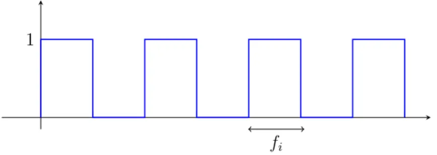
The channel constructions Cx must have a pre-set time period in which an artifact
is measured multiple times from the hardware. The average of these measurements can than be mapped to a single bit signal. The receiver or sender is constructed as a program which has a set number of iterations over the reception or transmission code used to take a single measurement from the hardware medium. Each iteration is one measurement and the number of iterations is the number of measurements averaged together. The time it takes for this number of iterations is a single time frame, fi,
used to measure a single bit.
The set number of iterations can be dynamically or statically increased in order to have a larger window in which to collect hardware measurements. This results in a higher likelihood for success in receiving the correct average measurement which maps to the correct bit.
Alternatively, this number can be decreased in order to allow for a fast receipt of a bit which decreases accuracy. This relationship holds true for n time frames in series used to collect an n bit message. In Figure 4.1, a series of time frames in series form a bit stream.
fi = time f rame to measure a bit
As there is one bit sent per time frame, the bandwidth of the channelCx, represented
as bi, is inversely correctly to fi.
bi =
1 fi
The time framefi is dependent on the constraints of the hardware medium,Hx, across
which theCx is built. This is an artifact of the time a single hardware measurement
takes to collect by the process. For example, hardware mediums located further from the processor are most likely mediums which have longer minimum time frames as it takes longer for a single query to physically reach the component.
1
fi
Figure 4.1: A bit stream, with each time frame and its average measure-ment representing a single bit
There are three channel constructions per eachHx, each which are implemented using
one of the channel architectures. This set ofCxwill have the same value for an optimal
bi and therefore offi given that these values are functions of the hardware component.
The reason for this invariability is that the transmission and reception processes iterate over code that is tailored to interact with a specific hardware medium. The code iterations do not depend on whether the processes are being used alone or jointly.
We show that the optimal fi and bi do not vary with channels of the same hardware
medium. We do this by choosing to use the three channel constructions, represented in this thesis by C1, C2, and C3 defined above, which are implemented using the central processor (CPU) hardware medium, Hcpu. Across these channels, variable
malware types will be implemented to show what attack vectors are possible across the three different architecture models.
We implement the three possible channel constructions, C1, C2, and C3, across the central processing unit,Hcpu. To do this, we create a novel side channel by exploiting
a function necessary in modern processor optimization: out-of-order-execution.
5.1
Out of Order Execution
In constructing the three channel types, out-of-order-execution must be exploited. To exploit this behavior, we create an algorithm which reliably forces out-of-order-execution occurrences across all shared CPU’s. This implies that the algorithm itself must not overload the processor and get optimized off of the shared hardware.
Also known as dynamic scheduling, out of order execution is a direct result of proces-sor optimization [23]. To increase processing power, modern computer architecture implements multi-staged pipelining, allowing for simultaneous execution of multiple instructions. Ideally, this occurs every clock cycle at full capacity, however hazards arise which degrade the overall performance time of the machine. One such hazard would be a delay caused by an instruction set which requires a great deal of cycles and there are other instructions require its output [24, 25].
For example, take loads and stores to main memory which both require many more cycles than an arithmetic operation. If the information used in either instruction is necessary for future operations the processor creates a bubble to avoid a potential hazard which results in computational errors [23]. This bubble is a delay in the
struction pipeline until the hazard has passed.
Processor optimization fills in the resulting pipeline bubbles with instructions that have been determined not to depend on the current pending ones. This is called out of order execution, when instruction execution order in the processor is not the order sent to it from higher level processes.
All hazards resolved by this method result in a pipeline order which is determined by the processor to be executed without hazards. However the processor does return the output to the higher processes in the order that it was given, ideally with the logically correct computation results [25].
5.2
Exploiting Out of Order Execution
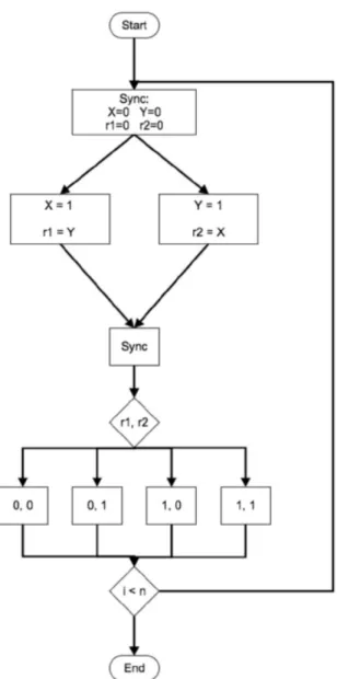
Certain reordering scenarios result in computations that are not expected. Take for example two threads, one with initial valuesX = 0 and r1 = 0, the other with initial values Y = 0 and r2 = 0. When the program executes, X =Y = 1 and a swapping occurs where r1 = Y and r2 = X. Logically, the expected final values of r1 and r2 should be respectively (0,1) or (1,0) depending on which thread executes fastest. Alternatively in the case of syncing threads, (1,1) may also be expected. However, if the thread instructions are executed out of order, where r1 and r2 are set before the values ofY and X, then the final values ofr1 andr2 will be (0,0). A diagram of this process can be illustrated as seen in Figure 5.1
Figure 5.1: Two threads depicting possible results of the swap
The illogical output, (0,0) can be exploited as an unintended leaking of processor behavior. A program will record external environment changes by measuring the fre-quency of the four different outputs.
Iterating through this computation many times returns an average frequency of out-of-order-execution outputs divided by total number of outputs recorded, or number of iterations. Comparing this frequency against a baseline frequency exposes valuable system information of all processes running on a certain set of shared cores.
5.3
Transmitting and Receiving Processes
We construct the three channel architectures: exfiltrating, infiltrating, and network as separate side channel. To do this, a pair of transmitting and receiving processes exploit the shared central processing unit. The transmitter must force out-of-order-execution to occur and the receiver must record these occurrences.
The receiver is constructed using the method described above to record out-of-order-execution occurrences. A loop in constructed for each time frame which iterates over a single measuring function. This function contains the two threads used to record one of four operation results. After the loop is complete, the sum of out-of-order-execution results is divided by the total number of iterations to get a percentage. This percentage is compared against a baseline percent of out-of-order-executions to determine if the sending process is transmitting a high bit. The absence of a high bit received in a single time frame implies a low bit. Pseudo code representative of this process used to retrieve a single bit signal is seen in Algorithm 1.
The transmitting process forces the shared central processing unit to execute the operations of the sending processes two threads out of order in order to transmit
Algorithm 1Receiver Pseudo-Code
1: procedure ReceiveBit
2: n ←# of iterations in time frame fi
3: sum←0 . The summation of OoOE
4: for k= 0, k++, while k < n do
5: X←0 . The initial variable values
6: r1 ←0 7: Y ←0 8: r2 ←0
9: parallelZ ←(X kY), rn ←(r1 kr2) do
10: Z ←1 .Two threads setting variables in parallel 11: rn← ¬Z
12: end parallel
13: if r1 ≡0 AND r2 ≡0 then
14: sum+ = 1 .The (0,0) case implies OoOE occurred
15: end if
16: end for
17: if sum÷n ≥threshold % then
18: return1 . A high bit is received
19: end if
20: return 0 . A low bit is received
21: end procedure
a single high bit. To send a low bit, the transmitting process simply refrains from operating, allowing the processor to execute the receiving threads in one of the three expected orders. The construction of this transmitter relies on a shared time frame, fi, which is representative of the time it takes the receiver to complete n iterations
in the ReceiveBit procedure, see Algorithm 1.
During this time frame, the transmitting process may repeatedly execute out-of-order-execution inducing assembly instructions. These are memory fence instructions, in x86, mfence, lfence, and sfence, used to force the processor to complete the time in-tensive transmitting process loads before the loads of the receiver.
This means that the processor optimizes the receiver operations by preemptively loading variable values needed to be stored before these variables are altered. In Figure 5.2, the second move instruction in both threads requires this targeted load of the variable value.
Figure 5.2: The store instructions in both receiver threads; the second move requires a reorderable load in the processor
In transmitting a high bit, the sending process alters the order of the receiver’s thread instructions in the processor as can be seen in Algorithm 2. In transmitting a low bit, no interfering instructions are executed. Either operation happens continuously during the given time frame.
Algorithm 2Processor Delayed Stores, Preemptive Loads
1: procedure ProcessorReorder . assuming all variables set to 0
2: parallel Z ←(X kY), rn←(r1 kr2) do
3: load [ Z] .loading value, storing in subsequent variable 4: store [ rn]
5: load 1 6: store [ Z]
7: end parallel
5.4
Construction of Seven Attacks
We construct a simplistic out-of-order-execution side channel. We use this to deploy an application from each of the seven attack models. The current CPU side channel construction is tailored to the contrived testing environment where there are only a few virtual machines running.
Using the requirements of a successful covert channel discussed earlier in this the-sis, we present Figure 5.3 highlighting a complete attack vector. These stages include determining co-residency, a requirement for any hardware based exploitation. Next, the physical interference or observation of a specific hardware unit, below the L1 cache is listed. Then noise reducing functions applied to the received data to average away noise and other environment variables. And finally, the malware can eavesdrop from inside the receiving process based on information leaked from co-resident virtual machines.
For the sake of our implementation, we assumed that co-residency is pre-determined. Also, that a satisfactory noise canceling algorithm was used. These assumptions were implemented by reducing the total number of running virtual machines to 6, all of which were instantiated on a single Xen server using software configurations which reflect those of the Amazon Cloud Computing service[26].
The implemented side channel by adversarial virtual machines is comprised of a single sender and receiver as described above in Section 4.2. Attack models which require only an active receiver to operate fall under the exfiltration category described pre-viously in this thesis. Similar categorization of attack models as either infiltration or network programs holds true for models requiring only a sender or both processes.
Figure 5.3: A complete diagram of the different stages of a deployed attack in a live, cloud computing environment
For the sake of this thesis, 7 different attacks, one Mx from each malicious attack
type found in Section 3.6, is implemented to test for time frame, fi, applicability
to different architecture models, success limitations, susceptibility to noise, and de-tectability. A listing of the specific attack objectives, ordered by the malicious attack type they belong to, can be seen below.
Implemented Attacks
M1 = encryption key theft
M2 = detection of co-located running program
M3 = capturing unique environment ids
M4 = malicious process triggered
M5 = interfere with coresident CPU usage
M6 = colluding VM detection
M7 = botnet communication
Where M1−4 require only a receiving program, M5−6 require only a sending pro-gram, andM7 requires both a sender and a receiver. The metrics used to assess each implementation are applied uniformly across all process and are further detailed in the following subsection.
5.5
Metrics
5.5.1 Success
The success of applying a malicious application, Mx, across chosen channel, Cx, can
be measured. First, through the ability for the malware to function using only the processes of the channel. This will be measured by flagging the malicious application as being either C1, C2 or C3 compatible. This means that it relies on that specific sender or receiver process to operate.
Additionally we record whether more than a single bit is needed to a received or transmitted signal in order to make it useful to the malware’s functionality. This will give insight into the overhead necessary to complete the attack. We measure this metric against an optimal bandwidth, bi, and time frame, fi.
Applicable Channels C1, C2,C3
Minimum Bits Required for Success of Attack 1-bit / 1 Process Alteration
5.5.2 Efficiency
The efficiency of the malicious side channel attack will be measured. Specifically, we measure the speed and capacity of the malware.On a larger scale, the possibility of repeating the same malicious attack is measured in the number of repetitions possible until degradation of the channel. This gives insight into the malware’s persistence and potential scope. An efficient attack will not vary under continual use.
5.5.3 Detectability
A major component of the malicious attack model is avoiding detection. We measure the level at which it can avoid observation or any unwanted identification. To test the covertness of the channel, the potential for defensive mechanisms applied by the server host assessed. Specifically, we measure the possibility for an intelligent sched-uler or hypervisor to detect unwarranted hardware behavior.
Finally, we look at several detection techniques used in malware detection and apply it to malware across hardware side channels. These include, malicio