Available Online at www.ijcsmc.com
International Journal of Computer Science and Mobile Computing
A Monthly Journal of Computer Science and Information Technology
ISSN 2320–088X
IMPACT FACTOR: 6.017IJCSMC, Vol. 6, Issue. 5, May 2017, pg.209 – 217
Seismic Analysis of Elevated Water
Tank with Variations of H/D Ratio
and Container Shape
Shriram Nagorao Bengal
1, Sandip A. Tupat
2¹Dept. of Civil Engg & Ballarpur Institute of Technology (BIT), Gondwana University, Gadchiroli (MS), India
²Dept. of Civil Engg & Ballarpur Institute of Technology (BIT), Gondwana University, Gadchiroli (MS), India
1
[email protected]; 2 [email protected]
Abstract— As known from very upsetting experiences, liquid storage tanks were collapsed or heavily damaged during the earthquakes all over the word. The economic lifetime of concrete or steel tanks is usually in the range of 40 to 75 years (ALA 2001).Damage or collapse of the tanks causes some unwanted events such as shortage of drinking and utilizing water, uncontrolled fires and spillage of dangerous fluids. Due to this reason numerous studies done for dynamic behavior of fluid containers; most of them are concerned with cylindrical tanks. In this study, Seismic forces acting on an Elevated water tank e.g. circular Tank and rectangular tank are studied with constant stagging height. Seismic forces acting on the tank are also calculated changing the Seismic Response Reduction Factor(R). IS: 1893-1984/2002 for seismic design and then checked the Design of Tanks by using the software STAAD PRO.
Keywords: - water tank, stagging system, staad pro, earthquake.
1. INTRODUCTION
can be of reinforced concrete with adequate cover to the reinforcement. Water and petroleum and react with concrete and, therefore, no special treatment to the surface is required. Industrial wastes can also be collected and processed in concrete tanks with few exceptions. The petroleum product such as petrol, diesel oil, etc. are likely to leak through the concrete walls, therefore such tanks need special membranes to prevent leakage. Reservoir is a common term applied to liquid storage structure and it can be below or above the ground level. Reservoirs below the ground level are normally built to store large quantities of water whereas those of overhead type are built for direct distribution by gravity flow and are usually of smaller capacity. Elevated tanks should remain functional in the post-earthquake period to ensure water supply is available in earthquake-affected regions. Never the less, several elevated tanks were damaged or collapsed during past earthquakes Due to the fluid–structure–soil/foundation interactions, the seismic behavior of elevated tanks has the characteristics of complex phenomena. Therefore, the seismic behavior of elevated tanks should be known and understood, and they should be designed to be earthquake-resistant. Some general programs have been carried out, which cover large amounts of data; these programs include STAAD PRO etc. However, a general-purpose structural analysis program generally exists in every engineering office. So, the evaluation of the applicability of these structural analysis programs in the design of elevated tanks is important from an engineering point of view and it will be helpful to present the application and results to designers. There is a second important reason that should be considered. That is, simplified models are used for a straightforward estimate of the seismic hazard of existing elevated tanks. Only if the estimated risk is high, it is convenient to measure all the data (e.g. geometry of the tank, material properties) that are required by the general finite element codes and to spend time and money to prepare a reliable general model.
2. SEISMIC ANALYSIS OF ELEVATED WATER TANK Seismic analysis of elevated water tank involved two types of analysis,
1. Equivalent Static analysis of elevated water tanks. 2. Dynamic analysis of elevated water tanks
Equivalent static analysis of elevated water tanks is the conventional analysis based on the conversion of seismic load in equivalent static load. IS: 1893- 2002 has provided the method of analysis of elevated water tank for seismic loading. Historically, seismic loads were taken as equivalent static accelerations which were modified by various factors, depending on the location’s seismicity, its soil properties, the natural frequency of the structure, and its intended use. Elevated water tank can be analyzed for both the condition i.e. tank full condition and tank empty condition. For both the condition, the tank can be idealized by one- mass structure. For equivalent static analysis, water-structure interaction shows, both water and structure achieve a pick at the same time due to the assumption that water is stuck to the container and acts as a structure itself and both water and structure has same stiffness. The response of elevated water tanks obtained from static analysis shows the high scale value. That’s why for large capacities of tanks, static response are not precise. If we analyzed the elevated water tank by static method and design by the same, we get over stabilized or say over reinforced section but it will be uneconomical. That’s why static systems of designing of elevated water tanks is not useful in seismic zones. And hence, IS code provision for static analysis is restricted for small capacities of tanks only.
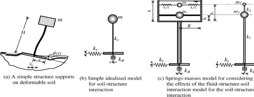
A. Single lumped-mass model
The concept that enables analysis of elevated water tanks as a single lumped-mass model was suggested in the 1950s (Chandrasekaran and Krishna, 1954). Elevated tanks (Fig. 1) and the selected model for this concept can be seen in Fig. 1(e). Two significant points should be discussed for this concept. The first point is related to the behavior of the fluid. If the container is completely full of water, this prevents the vertical motion of water sloshing, so the elevated tank may be treated as a single-degree-of-freedom system in such a case. When the fluid in the container (vessel) oscillates, this concept fails to characterize the real behavior. The other point is related to the supporting structures. As the ductility and the energy-absorbing capacities are mainly regulated by the supporting structure, this is important for the seismic design of elevated tanks. In this model, it is assumed that the supporting structure has a uniform rigidity along the height. The elevated tanks can have different types of supporting structures, which could be in the form of a steel frame, a reinforced concrete shell, a reinforced concrete frame or a masonry pedestal. Under seismic loads, the supporting structures that act as a cantilever of uniform rigidity along the height cannot represent all the supporting structure types. But it may be that these are more suitable for the reinforced concrete shell supporting structure.
The Indian seismic code, IS:1893, requires elevated tanks to be analyzed as a single-degree-of-freedom system—that is, a one-mass system—which suggests that all fluid mass participates in the impulsive mode of vibration and moves with the container wall (Rai, 2002). It must be stated that this can be a realistic assumption for long and slender tank containers with a height-to-radius ratio exceeding four. Also, the ACI 371R-98 (1995) suggests that the single lumped mass model should be used when the water load (Ww) is 80% or more of the total gravity load (WG) that includes: the total dead load above the base, water load and a minimum of 25% of the floor live load in areas that are used for storage. For this model, the lateral flexural stiffness of the supporting structure (ks) is determined by the deflection of the concrete supporting structure acting as a cantilever beam.
Fig. 2 Elevated tanks and the single lumped-mass model: (a) the tank with reinforced concrete shaft supporting structure, (b) the tank with reinforced concrete frame supporting structure, (c) the tank with reinforced concrete frame with diagonal braces or steel frame supporting structure, (d) the tank with masonry pedestal supporting structure, (e) single lumped-mass model.
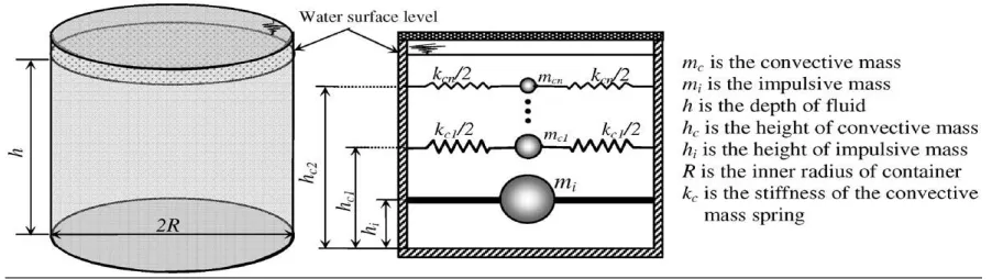
B. Double lumped-mass model
Most elevated tanks are never completely filled with liquid. Hence a two-mass idealization of the tank is more appropriate as compared to a one mass idealization, which was used in IS 1893: 1984. Two mass model for elevated tank was proposed by Housner (1963) and is being commonly used in most of the international codes.
3. METHODOLOGY
The methodology includes the selection of type of water tank, fixing the dimensions of components for the selected water tank and performing linear dynamic analysis (Response Spectrum Method of Analysis) by IS: 1893-1984 and IS: 1893-2002 (Part 2) draft code. In this study, various capacity circular and rectangular overhead water tank is considered for analysis. It is analyzed for four different zones (zone-II to V), and for two tank-fill conditions, i.e. tank full and tank empty conditions. Lastly, the results of the analysis of tanks performed on the basis of IS: 1893-1984 and IS: 1893-2002 (Part 2) draft code have been compared by using the software STAAD PRO software.
Step 1: Open STAAD. Pro and click on new project again click on space give file name and location, click on next add beam complete the task with proper directions.
Step 2: Now click on transalatinal circular repeat option make total no of steps =10 then click on link steps open base will appear select one reference point axis of rotation Y and click on ok.
Step 3: Assigning Properties: click on property then property dialog box will opens and give the property of column and click on add close now select all the columns, assign to selected beams make a proper completion assign yes.
Step 4: Go to define and rectangle finally give the property of lower beams and click on add close and select lower beams for assign to selected beams
Step 5: Go to define and select rectangle shape give the property of lower ring beam and click on add close to select lower beam assign to selected beams and assign.
Step 6: Go to define and rectangle arrangement give the property of upper ring beam and click on add close to select upper ring beam and assign to selected beams and assign.
Step 7: Go to define and thickness to give the property of plates and click on add close the select plates and assign to selected plates and assign.
give load or self weight to water tank assign to view assign yes.
Step 9: Go to load case details Add seismic load items dialog box will opens click on seismic load select type 1 Go to load case details add live load give name as hydrostatic load click on hydrostatic load items dialog box will opens click on plate loads select trapezoidal plate load direction of pressure Global Z Variation along element Y Give intensity as per height of the water tank multiplied by unit weight of water select required plates for hydrostatic force Assigned to selected plates Assign yes select lower plates of water tank give intensity according to its height assign hydrostatic load on lower portion of water tank.
Step 10: Go to load case details click on auto load combination select load combination type-Indian select load combination category –general structures click on generate loads add now go to analyze Run analysis go to post processing mode for required results. The same procedure will be followed to create models for different seismic loads.
4. DESIGN AND ANALYSIS OF WATER TANK
I. Circular Water Tank (Capacity 100m3) II. Rectangular Water Tank (Capacity 100m3
Circular Water Tank 100m3
Full Tank condition
Nodal Displacement
Zone
Horizontal Vertical Horizontal
Max
X Min X
Max Y
Min
Y Max Z Min Z
II 4.818 -4.818 0.138
-5.908 4.819 -4.819
III 7.709 -7.709 0.221
-5.908 7.711 -7.711
IV 11.563
-11.563 0.331
-5.908 11.567 -11.567
V 17.344
-17.344 0.496
-5.908 17.35 -17.35
Base Shear
Zone
Fx kN Fy kN Fz kN
II 9.705 433.205 9.705
III 15.528 433.205 15.527
IV 23.292 433.205 23.291
V 34.939 433.205 34.937
Base Moment
Zone
Mx kNm My kNm Mz kNm
II 21.623 -0.001 21.623
III 34.596 -0.001 34.597
IV 51.894 -0.001 51.896
V 77.841 -0.001 77.844
Shear Force
Zone
Fx kN Fy kN Fz kN
II 38.812 -1070.67 38.812
III 62.099 -1070.67 62.099
IV 93.148 -1070.67 93.148
V 139.722 -1070.67 139.722
Bending Moment
Zone
Mx kNm My kNm Mz kNm
II 52.992 116.435 52.992
III 84.787 186.296 84.787
V 190.771 419.166 190.771
Empty Tank condition
Base Shear
Base Moment
Zone
Mx kNm My kNm Mz kNm
II 21.623 0 21.623
III 34.596 0 34.597
IV 51.894 0 51.896
V 77.841 0 77.844
Shear Force
Zone
Fx kN Fy kN Fz kN
II 38.812 -618.767 38.812
III 62.099 -618.767 62.099
IV 93.148 -618.767 93.148
V 139.722 -618.767 139.722
Nodal Displacement
Zone
Horizontal Vertical Horizontal
Max X Min X Max Y Min
Y Max Z Min Z
II 4.818 -4.818 0.138 -4.06 4.819 -4.819
III 7.709 -7.709 0.221 -4.06 7.711 -7.711
IV 11.563
-11.563 0.331 -4.06 11.567 -11.567
V 17.344
-17.344 0.496 -4.06 17.35 -17.35
Zone
Fx kN Fy kN Fz kN
II 9.705 267.721 9.705
III 15.528 267.721 15.527
IV 23.292 267.721 23.291
Bending Moment
Zone
Mx kNm My kNm Mz kNm
II 52.992 116.435 52.992
III 84.787 186.296 84.787
IV 127.181 279.444 127.181
V 190.771 419.166 190.771
Rectangular Water Tank 100m3 > Full Tank condition
Nodal Displacement
Zone Horizontal Vertical Horizontal
Max X Min X Max
Y
Min
Y Max Z Min Z
II 6.382 -6.382 0.108
-3.497 5.124 -5.124
III 10.211
-10.211 0.173
-3.497 8.198 -8.198
IV 15.316
-15.316 0.26
-3.497 12.298 -12.298
V 22.974
-22.974 0.389
-3.497 18.447 -18.447 Base Shear
Zone
Fx kN Fy kN Fz kN
II 10.35 377.929 10.35
III 16.559 377.929 16.559
IV 24.839 377.929 24.839
V 37.259 377.929 37.259
Base Moment
Zone
Mx kNm My kNm Mz kNm
II 22.801 0.008 26.104
III 36.481 0.008 41.767
IV 54.722 0.008 62.65
V 82.082 0.008 93.976
Shear Force
Zone
Fx kN Fy kN Fz kN
III 66.237 -1142.025 66.237
IV 99.356 -1142.025 99.356
V 149.034 -1142.025 149.034
Bending Moment
Zone
Mx kNm My kNm Mz kNm
II 3023.428 144.894 59.34
III 3023.428 231.831 94.944
IV 3023.428 347.747 142.415
V 3023.428 521.62 213.623
Empty Tank condition
Nodal Displacement
Zone
Horizontal Vertical Horizontal
Max
X Min X Max Y Min Y Max Z Min Z
II 6.382 -6.382 0.108 -1.351 5.124 -5.124
III 10.211
-10.211 0.173 -1.351 8.198 -8.198
IV 15.316
-15.316 0.26 -1.351 12.298
-12.298
V 22.974
-22.974 0.389 -1.351 18.447 -18.447 Base Shear
Zone
Fx kN Fy kN Fz kN
II 10.35 285.506 10.35
III 16.559 285.506 16.559
IV 24.839 285.506 24.839
V 37.259 285.506 37.259
Base Moment
Zone
Mx kNm My kNm Mz kNm
II 22.801 0.002 26.104
III 36.481 0.002 41.767
IV 54.722 0.002 62.65
V 82.082 0.002 93.976
Shear Force
Zone
Fx kN Fy kN Fz kN
IV 99.356 -391.714 99.356
V 149.034 -391.714 149.034
Bending Moment
Zone
Mx kNm My kNm Mz kNm
II 2284.051 144.894 59.34
III 2284.051 231.831 94.944
IV 2284.051 347.747 142.415
V 2284.051 521.62 213.623
5. CONCLUSION
Following are the conclusions based on the Seismic Analysis of Elevated Water Tank are as follows:
1. Base shear of full water tank and empty water tank are increased with seismic zone II-V because of zone factor, response reduction factor etc. while considering seismic analysis.
2. Base shear in full condition tank is slightly higher than empty tank due to absence of water or hydro static pressure.
3. Displacement of full water tank and empty water tank are increased with seismic zone II-V because of zone factor, response reduction factor etc. while considering seismic analysis.
4. Maximum nodal displacement and minimum nodal displacement found at the wall of water tank when tank is full condition.
5. Shear force and bending moment of full water tank and empty water tank are increased with seismic zone II-V because of zone factor, response reduction factor etc. while considering seismic analysis. 6. Shear force and bending moment in full condition tank is slightly higher than empty tank due to
absence of water or hydro static pressure.
REFERENCES
[1]. Jain Sudhir K., Sameer U.S., 1990, ―Seismic Design of Frame Staging For Elevated Water Tank‖ Ninth Symposium on Earthquake Engineering (9SEE-90), Roorkey, December 14-16, Vol-1.
[2]. Sudhir K.Jain & O.R.Jaiswal, September-2005, Journal of Structural Engineering Vol-32, No.03.
[3]. Ranjit Singh Lodhi & Dr.Vivek Garg., (2014). ―Design of Intze Tank in Perspective of Revision of IS: 3370, Vol.-03 Issue No.9, pp: 1193-1197.
[4]. Luis A. Godoy, ―Damage Due to Buckling in Above Ground Storage Tank‖, University of Puerto Rico, Mayaguez, PR 00681-9041, Puerto Rico.
[5]. Irwin P, Kilpatrick J and Frisque A (2008) ―Friend or Foe, Wind Height‖. CTBHU 8th World Congress Aatish Kumar., R.K.Pandey., 2013, ―Wind Effects on Overhead Tank under Different Soil Parameters‖ IJEAT Vol.-2, No.-6.
[6]. I.S 1893 (Part I) -1984, ―Criteria for Earthquake Resistant Design of Structures‖.
[7]. IS: 3370 (Part I-II) -2009, General Requirements, Code of Practice for Concrete Structures for the Storage of liquids.
[8]. IS: 3370 (Part IV) -1967, Design Tables, Code of Practice for Concrete Structures for the Storage of liquids. [9]. IS: 875 (2002) ―Code of Practice for Design Load‖ Bureau of Indian Standard, New Delhi.