SCATTERING FROM BODIES COATED WITH METAMATERIAL USING FDFD METHOD
S. H. Zainud-Deen
Faculty of Electronic Engineering Menoufia University
Menouf, Egypt
A. Z. Botrosand M. S. Ibrahim Faculty of Engineering
Cairo University Cairo, Egypt
Abstract—The electromagnetic scattering from a conducting object coated with metamaterials, which have both negative permittivity and permeability is derived rigorously by using finite difference frequency domain (FDFD). A formulation for the FDFD method is presented. The scattering from circular and multilayers elliptic cylinder coated by metamaterial are investigated. Also, the scattering from dielectric and metamaterial sphere is depicted. Numerical results are compared with the available data in the literature.
1. INTRODUCTION
advent of a newclass of metamaterials exhibiting negative constitutive parameters reveals that these fundamental concepts should be revis-ited since media now exist wherein waves are totally reflected when propagating at angles belowthe critical angle, and transmitted when propagating at angles above the critical angle. In addition, within the region of transmission, a Brewster angle might exist in some cases, yielding an inversion of critical angle and Brewster angle, namely the Brewster angle appears beyond the critical angle, and not below like it is currently well-accepted [2–4].
Scattering of electromagnetic waves by complex-shaped metama-terial objects is an interesting research subject to develop potential application of this artificial material. The electromagnetic scatter-ing from sscatter-ingle and array of cylinders coated by metamaterials, which have both negative permittivity and permeability, for both normal and oblique incidence had been studied in [5–8]. Only two-dimensional cases are considered.
In this paper, the electromagnetic scattering from objects coated by metamaterials is investigated. Two- and three-dimensional objects are considered. The Finite-Difference Frequency-Domain (FDFD) method is formulated for the objects coated with metamaterial and used to calculate the scattering from different objects and compared with the available published results. The FDFD is simplest in formulation and most flexible in modeling arbitrarily shaped inhomogeneously filled and anisotropic scatterers [9–12].
2. THEORETICAL BACKGROUND
Finite-Difference Frequency-Domain Technique for Metama-terials:
Considering a region of space that is source free, but may have materials that absorb electric or magnetic field energy, then Maxwell’s curl equations in frequency domain are
∇xEtotal=−jωµHtotal−σ∗Htotal=−jnkoη
1 + σ ∗
jnkoη
Htotal,
(1a)
and
∇xHtotal= (jωε+σ)Etotal=j
nko
η
1 + σ
jnko η
The wave number and intrinsic impedance for the object are:
k = nko
n = +√µrεr for dielectric object,
n = −√µrεr for Metamaterial object
Define the total fields as sum of incident and scattered fields:
Etotal =E inc
+Escat, and Htotal=H inc
+Hscat (2)
where Einc, and Escat are the incident and the scattered field respectively. The incident field is the field which propagates in computation domain when no scatters exist. If the background of the computation domain is free space, then Maxwell’s curl equations can be rewritten as:
∇xEscat+jnkoη
1+ σ ∗
jnkoη
Hscat=
jkoηo−jnkoη
1+ σ ∗
jnkoη
Hinc
(3)
∇xHscat−jnko η
1+ σ
jnko η
Escat=
−jko
ηo
+jnko η
1 + σ
jnko η
Einc
(4)
Maxwell’s equations can be reduced to two sets of scalar equations (i.e., TMz and TEz) in two dimensional case.
Using the central difference algorithm to solve for the space derivatives, Yee introduced his algorithm [13], in 1966 to solve Maxwell’s partial differential equations. Yee discretized the space of the problem to small cubical cells (rectangular cells in 2D case) and for each cell he locates the six field components to match the curl equations. Discrete equations given beloware obtained by replacing derivatives in these equations with their finite-difference approximations. At the boundaries of the computational domain, the perfectly matched layer boundary condition (PML) is used to absorb all the outgoing radiation. The derivation of the PML is discussed in details by Berenger [14].
For the TM Case:
The FDFD iterative equations are
Hxscat(i, j) =
1
jn(i, j)koηxy(i, j)
1 + σ∗xy(i,j) jn(i,j)koηxy(i,j)
Ezscat(i, j)−Ezscat(i, j+ 1)
ηo−n(i, j)ηxi(i, j)
1 + σxi∗(i,j) jn(i,j)koηxi(i,j)
n(i, j)ηxi(i, j)
1 + σ∗xi(i,j) jn(i,j)koηxi(i,j)
Hxinc(i, j) (5)
Hyscat(i, j) =
1
jn(i, j)koηyx(i, j)
1 + σ∗yx(i,j) jn(i,j)koηyx(i,j)
Ezscat(i+ 1, j)−Ezscat(i, j)
∆x +
ηo−n(i, j)ηyi(i, j)
1 + σ∗yi(i,j) jn(i,j)koηyi(i,j)
n(i, j)ηyi(i, j)
1 + σyi∗(i,j) jn(i,j)koηyi(i,j)
Hyinc(i, j) (6)
Ezscat(i, j) + H
scat
y (i−1, j)−Hyscat(i, j)
jn(i,j)ko ηzx(i,j)
1 + σzx(i,j) jn(i,j)ko ηzx(i,j)
ωεzx(i, j)∆x
+ H
scat
x (i, j)−Hxscat(i, j−1)
jn(i,j)ko ηzy(i,j)
1 + σzy(i,j) jn(i,j)ko ηzy(i,j)
ωεzx(i, j)∆y
=
ηzi−n(i, j)ηo(i, j)
1 + σzi(i,j) jn(i,j)ko ηzi(i,j)
n(i, j)ηo(i, j)
1 + σzi(i,j) jn(i,j)ko ηzi(i,j)
Ezinc(i, j) (7)
then
a(i, j)Ezscat(i+ 1, j) +b(i, j)Ezscat(i−1, j) +c(i, j)Ezscat(i, j+ 1) +d(i, j)Ezscat(i, j−1) +e(i, j)Ezscat(i, j) =f(i, j) (8)
where
a(i, j) = ηzx(i, j) (ko∆xn(i, j))2ηyx(i, j)
1 + σzx(i,j) jn(i,j)ko ηzx(i,j)
1 + σyx∗ (i,j) jn(i,j)koηyx(i,j)
b(i, j) =
ηzx(i, j)
(ko∆x)2n(i, j)n(i−1, j)ηyx(i−1, j)
1+ σzx(i,j) jn(i,j)ko ηzx(i,j)
1+ σ∗yx(i−1,j) jn(i−1,j)koηyx(i−1,j)
c(i, j) = ηzy(i, j) (ko∆y)2n(i, j)n(i, j)ηxy(i, j)
1+ σzy(i,j) jn(i,j)ko ηzy(i,j)
1+ σxy∗ (i,j) jn(i,j)koηxy(i,j)
d(i, j) =
ηzy(i, j)
(ko∆y)2n(i, j)n(i, j−1)ηxy(i, j−1)
1+σzy(i,j) jnηzy(i,j(i,j)ko)
1+ σ∗xy(i,j−1) jn(i,j−1)koηxy(i,j−1)
e(i, j) = 1−a(i, j)−b(i, j)−c(i, j)−d(i, j),
and
f(i, j) =
ηzi(i, j)−n(i, j)ηo
1 + σzi(i,j) jn(i,j)ko
ηzi(i,j)
n(i, j)ηo
1 + σzi(i,j) jn(i,j)ko
ηzi(i,j)
Ezinc(i, j)−
(ηo−n(i, j)ηyi(i, j))
1+ σ∗yi(i,j) jn(i,j)koηyi(i,j)
jn(i,j)ko∆x ηzx(i,j)
1+ σzx(i,j)
jn(i,j)ko ηzx(i,j)
n(i, j)ηyi(i, j)
1+ σ∗yi(i,j) jn(i,j)koηyi(i,j)
Hyinc(i, j)−
(ηo−n(i−1, j)ηyi(i−1, j))
1+ σyi∗(i−1,j) jn(i−1,j)koηyi(i−1,j)
jn(i,j)ko∆x ηzx(i,j)
1+ σzx(i,j)
jn(i,j)ko ηzx(i,j)
n(i−1, j)ηyi(i−1, j)
1+ σyi∗(i−1,j) jn(i−1,j)koηyi(i−1,j)
Hyinc(i−1, j)+
(ηo−n(i, j)ηxi(i, j))
1 + σ∗xi(i,j) jn(i,j)koηxi(i,j)
jn(i,j)ko∆y ηzy(i,j)
1 + σzy(i,j) jn(i,j)ko ηzy(i,j)
n(i, j)ηxi(i, j)
1 + σ∗xi(i,j) jn(i,j)koηxi(i,j)
Hxinc(i, j) +
(ηo−n(i, j−1)ηxi(i, j−1))
1+ σ∗xi(i,j−1) jn(i,j−1)koηxi(i,j−1)
jn(i,j)ko∆y ηzy(i,j)
1+ σzy(i,j)
jn(i,j)ko ηzy(i,j)
n(i, j−1)ηxi(i, j−1)
1+ σ∗xi(i,j−1) jn(i,j−1)koηxi(i,j−1)
Hxinc(i, j−1)
Out of the PML Region:
ηxy =ηx, σ∗xy =σx∗, ηxi =ηx, σxi∗ =σ∗x, ηyx=ηy, σyx∗ =σy∗, ηyi=ηy,
σyi∗ =σ∗y, ηzx=ηz, σzx=σz, ηzy=ηz, σzy=σz, ηzi=ηz, and σzi=σz
and in PML Region:
ηxy =ηo, σ∗xy =σym, ηxi =
ηo
n, σ
∗
xi= 0, ηyx=ηo, σyx∗ =σxm, ηyi=
ηo
σyi∗ = 0, ηzx=ηo, σzx=σex, ηzy=ηo, σzy =σye, ηzi=nηo, and σzi= 0
σe, σm: are electric and magnetic conductivity distributions in PML layer respectively, σεe = σµm for perfect matching between free space and the PML region, and
σe,m(h) =σmax
h δP M L
n+1
where σmax = −εoc(n+1) ln[R(0)]
2δP M L , σmax: is the maximum conductivity,
δP M L is the thickness of the PML layer, h is the distance from the
inner boundary of PML, R(0) is the theoretical reflection factor at normal incidence, and n is the type of the conductivity distribution.
n= 2 for parabolic conductivity.
The above procedure is followed in the case of the three dimensional case. Six components for the electric and magnetic fields are derived and Equations (3) and (4) can be reduced to three equations, in terms of the three scattered electric field components by eliminating the scattered magnetic field terms, which can then construct a linear set of equations. These final equations are used to construct a system of linear equations which can be written in the form Ax = y. A is a coefficient matrix, y is a vector related to the incident fields andx is the vector of unknown electric fields [10]. The number of cells in the 3D component domain isN =NxxNyxNy. The
matrixAis a sparse matrix of size (3N×3N) andx is a vector of size (3N ×1). Biconjugate gradients method is used to solve Ax=y.
3. NUMERICAL RESULTS
In this section, sample numerical results are presented to proof the validity of the developed formulation for computing the radar cross section (RCS) of a single cylinder coated with metamaterial, a linear array of coated cylinders are calculated and compared with the available data in the literature.
For 2D problems the radar cross section is given by [1]
σ = lim
ρ→∞2πρ
E¯scat2
E¯inc2 for TMz case (9)
and
σ = lim
ρ→∞2πρ
H¯scat2
x incident
wave
y
1 1,ε
µ
2 2,ε
µ
o
o ε
µ , 1 a
2 a
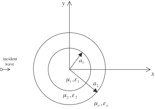
Figure 1. Geometry of 2D case.
the geometry of the problem considered in 2D case is shown in Fig. 1. The metamaterial parameters used in this paper are selectively used to provide confirmation of the validity of the newformulation by comparison of special cases with published results.
Figures 2, 3 showthe computation of the RCS (TM and TE incidence) per unit length in case of a PEC (perfect electric conductor) cylinder coated by a DPS (Double Positive) or a DNG (Double Negative) layer, which is illuminated by a unit plane wave polarized along z-axis and propagating along x-axis (incidence angle is θi =π)
wherea1 = 0.05 m, anda2= 0.10 m. The operating frequency is 1 GHz. The dielectric parameters are given by: ε2 = 9.8εo, and µ2 =µo, for
the DPS case, and ε2 =−9.8εo, and µ2 =−µo, for the DNG case. It
is observed that the RCS of TM incidence are of similar behavior: the both have large forward scattering. However, as shown in Fig. 2 for TE incidence, a cylinder coated with a conventional material has smaller forward scattering compared to a cylinder coated with a metamaterial. The results are in very good agreement with those obtained by Li and Shen [6].
Figure 4 shows the RCS of two layer dielectric (ε2 = 9.8εo, and
µ2 = µo) and metamaterial (ε2 = −9.8εo, and µ2 = −µo) circular
cylinder (a1 = 0.05 m, a2 = 0.10 m) illuminated by a TM plane wave
at f = 300 MHz and θ = π compared with Matteo [15] and good agreement between those two results.
0 50 100 150 200 250 300 350 400 0
1 2 3 4 5 6 7 8
φ (Degrees)
σ
/λ
o
Dielectric coating FDFD Dielectric coating [6] Metamaterial coating FDFD Metamaterial coating [6]
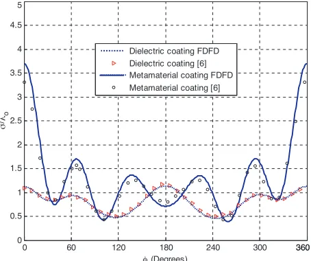
Figure 2. Bistatic RCS for a coated PEC circular cylinder (a1 = 0.05 m, a2 = 0.10 m) illuminated by a TM plane wave at f = 1 GHz;
θ =π and material properties (DPS case: (ε2 = 9.8εo and µ2 = µo);
DNG case: (ε2 =−9.8εo and µ2 =−µo)).
0 60 120 180 240 300 360360
0 0.5 1 1.5 2 2.5 3 3.5 4 4.5 5
(Degrees) Dielectric coating FDFD Dielectric coating [6] Metamaterial coating FDFD Metamaterial coating [6]
φ
σ
/λ
o
Figure 3. Bistatic RCS for a coated PEC circular cylinder (a1 =
0.05 m, a2 = 0.10 m) illuminated by a TE plane wave at f = 1 GHz; θ =π and material properties (DPS case: (ε2 = 9.8εo and µ2 = µo);
0 60 120 180 240 300 360360 0
0.2 0.4 0.6 0.8 1 1.2
(Degrees) DNG FDFD DPS FDFD Matteo DNG [15] Matteo DPS [15]
φ
σ
/λ
Figure 4. Bistatic RCS for two layer dielectric (ε2 = 9.8εom and
µ2 = µo) and metamaterial (ε2 = −9.8εom and µ2 = −µo) circular
cylinder (a1 = 0.05 m, a2 = 0.10 m) illuminated by a TM plane wave
atf = 300 GHz andθ=π.
0 50 100 150 200 250 300 350
0 1 2 3 4 5 6
Dielectric TM FDFD [9] Metamaterial TM FDFD Dielectric TE FDFD [9] metamaterial TE FDFD
1 a
1
ε
2
ε
3
ε
4
ε
4
a 1 b
incident wave
Figure 5. Radar cross section pattern of a four-layered cylinder (a1 = 0.3λ, a2 = 0.25λ, a3 = 0.2λ, a4 = 0.15λ), and bi = ai/2,
(i= 1 : 4), TMzand TEzplane wave for conventional and metamaterial
0 20 40 60 80 100 120 140 160 180 -40
-35 -30 -25 -20 -15 -10 -5 0
θ (Degrees)
σ
/
λ
2(d
B
)
Dielectric sphere [10] Metamaterial sphere
Figure 6. Bistatic RCS for dielectric and metamaterial sphere (εr = ±4, radius = 0.5 m) atf = 100 MHz.
cylinder with a1 = 0.3λ, a2 = 0.25λ, a3 = 0.2λ, a4 = 0.15λ, bi =ai/2,(i= 1 : 4), γ = 2, εr1 = 8, εr2 = 6, εr3 = 4, andεr4 = 2 for
either TMz or TEz incident plane wave and for metamaterial [9].
Figure 6 compares the bistatic RCS for a dielectric sphere (εr =
4.5, µr = 1, r = 0.5 m), and for a metamaterial sphere (εr = −4.5,
µr =−1, r = 0.5 m) in the x-z plane with the resonance frequency is
100 MHz. The angle of incidences (θi= 0◦ and ϕi= 0◦).
4. CONCLUSIONS
REFERENCES
1. IEEE Transaction on Antennas and Propagation Special Issue on Metamaterials, Vol. 51, No. 10, Part I, Oct. 2003.
2. Caloz, C. and T. Itoh, Electromagnetic Metamaterials: Trans-mission Line Theory and Microwave Applications, John Wiley & Sons, Inc, NewYork, USA, 2006.
3. Eleftheriades, G. V.,Negative-Refraction Metamaterials, 2005. 4. Markley, L. and G. V. Eleftheriades, “A negative-refractive-index
metamaterial for incident plane waves of arbitrary polarization,”
IEEE Antennas and Wireless Propagation Letters, Vol. 6, 28–32, 2007.
5. Qiu, C.-W., H.-Y. Yo, S.-N. Burokur, S. Zouhdi, and L.-W. Li, “Electromagnetic scattering properties in a multilayered metamaterial cylinder,”IEIC Trans. Commun., Vol. E90-B, No. 9, 2423–2429, September 2007.
6. Li, C. and Z. Shen, “The electromagnetic scattering by a conducting cylinder coated with metamaterials,” Progress In Electromagnetics Research, PIER 42, 91–105, 2003.
7. Shooshtari, A. and A. R. Sebak, “Electromagnetic scattering by parallel metamaterial cylinders,”Progress In Electromagnetics Research, PIER 57, 165–177, 2006.
8. Henin, B. H., M. Al-Sharkawy, and A. Z. Elsherbeni, “Scattering of obliquely incident plane wave by array of parallel concentric metamaterial cylinders,” Progress In Electromagnetics Research, PIER 77, 285–307, 2007.
9. Zainud-Deen, S. H., M. S. Ibrahim, and E. El-Deen, “A hybrid finite difference frequency domain and particle swarm optimization techniques for forward and inverse electromagnetic scattering problems”, The 23rd Annual Review of Progress in Applied Computational Electromagnetics, Verona, Italy, March 19–23, 2007.
10. Zainud-Deen, S. H., E. El-Deen, and M. S. Ibrahim, “Electro-magnetic scattering by conducting/dielectric objects,” The 23rd Annual Review of Progress in Applied Computational Electromag-netics, Verona, Italy, March 19–23, 2007.
11. Henin, B. H., A. Z. Elsherbeni, and M. Al-Sharkawy, “Oblique incidence plane wave scattering from an array of circular dielectric cylinders,”Progress In Electromagnetics Research, PIER 68, 261– 279, 2007.
concentric metamaterial cylinders,” Progress In Electromagnetics Research, PIER 77, 285–307, 2007.
13. Yee, K. S., “Numerical solution of initial boundary value problems using Maxwell’s equations in isotropic media,” IEEE Trans. Antennas Propagat., Vol. 14, 302–307, May 1966.
14. Berenger, J. P., “A perfectly matched layer for the absorption of electromagnetic waves,” J. Comput. Phys., Vol. 144, 185–200, Oct. 1994.