A Broadband Low Cross-Polarization U-Slot Patch Antenna Array
Based on Differential Feed
Zhimin Zhu*, Chunhong Chen, Yunjiao Chen, and Wen Wu
Abstract—In this paper, a single layer 4×4 U-slot patch antenna array based on differential feed was
developed to achieve a wide bandwidth and low cross polarization with a simple feed network. A U-slot was cut on a radiation patch to realize a wideband performance, and a microstrip-line fed structure was adopted to make the patch and feed network placed in a single layer. In order to reduce extra
cross-polarization level in theH-plane caused by cutting U-slot, differential feed is adopted, which also makes
it easily integrated with differential devices (such as differential amplifier) directly without baluns. A single layer U-slot patch array based on differential feed and an array having the same structure but based on normal feed were made and compared with each other. The designed differentially-fed patch array has more than 12% measured impedance bandwidth and stable gain at 18–19 dBi across the operating band from 5.2 to 5.88 GHz. The measured result shows that a better asymmetry of radiation
pattern in theE-plane and a lower than−45 dB cross-polarization level in theH-plane can be achieved
compared with normally-fed array.
1. INTRODUCTION
Microstrip patch antennas have become the favorite of antenna designers because of their versatility and advantages of planar profile, easy fabrication, compatibility with integrated circuit technology, and conformability with a shaped surface [1]. However, they also suffer from an obvious drawback — narrow bandwidth, which makes their application greatly restricted in wireless communication, high speed data transmission and other fields. Cutting a U-slot or E-slot on the patch, with simple structure and significant improvement in bandwidth, becomes one of the widely used methods to achieve a wideband and high gain performance [2]. An antenna fed by coaxial probe with a U-slot on the patch has been proved to provide impedance bandwidth of 10%–40%, even with nonair substrate [3]. However, this structure fed by coaxial probe makes it difficult to build an array in a single layer. A wideband U-slot patch antenna array based on aperture-coupled is proposed in [4], with a 27% impedance bandwidth. A wideband array whose U-slot patch and microstrip-line feed network were placed in the single layer was firstly proposed in [5], with a 18% impedance bandwidth.
However, a much greater cross-polarization level will be broughtbecause of U-slot generating new
current component while an improvement can be achieved in impedance bandwidth. In recent years,
differentially-fed patch antenna has been particularly studied because of its advantage in low cross-polarization and ease of being integrated with ready-made differential devices [6]. A differentially-fed microstrip antenna integrated with a push-pull power amplifier in complimentary metal oxide semiconductor technology is presented in [7]. A differentially-fed microstrip antenna integrated with an oscillator including a buffer amplifier in Silicon Germanium semiconductor technology is proposed in [8]. A single differentially-fed patch antenna was proposed in [9], with a symmetric co-polarization
Received 24 May 2016, Accepted 7 September 2016, Scheduled 25 October 2016
* Corresponding author: Zhimin Zhu ([email protected]).
by feeding two mirrored elements differentially. In [12], two differentially-fed Ku-band 2×2 patch antenna arrays using multilayer printed circuit board technology were developed, and an antenna array comprising a compact feed network is achieved by comparing with each other.
This paper presents a single layer 4×4 U-slot patch antenna array based on differential feed. A
microstrip-line fed structure was adopted to take the place of traditional coaxially feed, making patch and feed network placed in a single layer. In order to enhance the bandwidth of microstrip antenna, a U-slot was cut on the patch. The application of differential feed effectively eradicates the large cross-polarization generated by U-slot while making it easily integrated with differential devices directly without baluns. The test results show that a wider impedance bandwidth and lower cross-polarization levels can be achieved than normally-fed antenna.
2. WIDEBAND DIFFERENTIALLY-FED U-SLOT PATCH ELEMENT
The single U-slot patch element of the proposed antenna is illustrated in Fig. 1. It is designed at WLAN
bands using a Duroid 5880 substrate with a dielectric constant εr = 2.2 and thickness H = 3.175 mm.
The patch, with a U-slot located in the center, has a length Land widthW. Two vertical rectangular
slots and a horizontal rectangular slot of U-slot have the same width W d. The lengths of a horizontal
rectangular slot and two vertical rectangular slots are Lp and W p. The width of microstrip feedline is
W s.
In order to avoid the difficulties in design and manufacture of multilayer structure when structuring an antenna array, a microstrip-line fed structure was adopted so that the patch and feed network can be placed in a single layer, resulting in a simple structure. To enhance the bandwidth of antenna, a
U-slot near microstrip feedline is introduced. A new current path is introduced on the shorter patch,
making a new resonant point, because of the added U-slot dividing microstrip patch into two parts. A wider bandwidth can be achieved when these two resonant points are located in close frequency range. The simulated reflection coefficient of single U-slot patch adopted at last is shown in Fig. 2.
The simulated reflection coefficient shows 12.7% impedance bandwidth from 5.2 to 5.89 GHz for the
reflection coefficient less than−10 dB. Although the introduction of U-slot can increase the bandwidth,
the current component going along the horizontal rectangular slot will become very large in all the
bandwidth as shown in Fig. 3. Those currents will affect radiation patterns, especially in the H-plane
/ :V
/S
:S
:G S
:
Figure 1. Geometry of the single U-slot patch
element.
4.5 -30 -25 -20 -15 -10 -5 0
S
11
(
d
B
)
5.0
Freq
5.5 6.0
(GHz)
6.5
S11
Figure 2. Reflection coefficient of the single
(a) (b) (c)
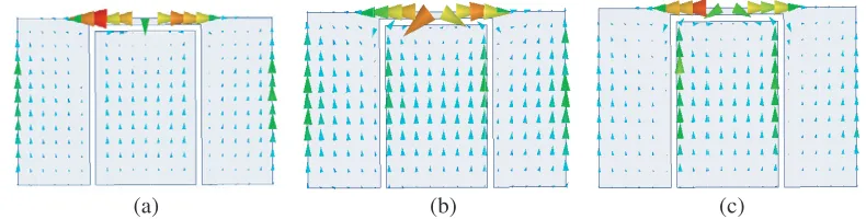
Figure 3. Current distribution on U-slot patch at different frequencies.
Figure 4. Structure of the differentially-fed U-slot patch antenna.
5.3 G 5.5 G 5.8 G
Figure 5. Current distributes on U-slot patch which based on differential feed at different frequency.
The dark arrows represent the directions of the horizontal and vertical currents.
(yoz-plane), resulting in a very high cross-polarization level. As for theE-plane (xoz-plane), the impact
on radiation patterns of this current component is very restricted. The undesirable cross-polarization level degrades the performance of the antenna. In order to improve the cross-polarization level in the
H plane,a differentially-fed U-slot patch antenna structure is demonstrated in Fig. 4. Dis the distance
of the two patches, and the other parameters are the same as single patch. Two lumped ports are used to take the place of microstrip feedline, making simulation more convenient in HFSS.
Due to the differential feed design, shown in Fig. 5, currents going through the horizontal arm of the U-slot on one patch are comparable with their image counterparts in amplitude, but with different
direction. This leads to cancelation of the radiation in the H-plane and results in much lower
cross-polarization compared with the single U-slot element design. This design will make the antenna not only have the advantage of wideband characteristic of the single U-slot element, but also achieve symmetric
radiation patterns and much lower cross-polarization levels in the H-plane.
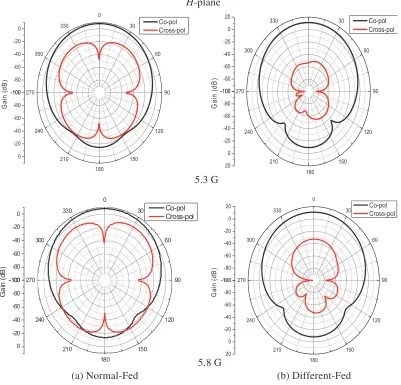
Figure 6 shows the cross-polarization level of a normally-fed U-slot patch and differentially-fed
U-slot patch in the H-plane from 5.3 GHz to 5.8 GHz when D= 50 mm. Compared with normally-fed
U-slot patch, it is obvious that a remarkable improvement is achieved when differentially-fed U-slot
-100 -80 -60 -40 -20 0 27 -100 -80 -60 -40 -20 0 Ga in ( d B ) 0 180 210 240 70 300 330 30 60 90 120 150 Co-pol Cross-pol Ga in (d B ) -10 -8 -10 -8 -6 -4 -2 Ga in ( d B ) -100 -80 -60 -40 -20 0 20 210 240 270 300 330 -100 -80 -60 -40 -20 0 20 00 80 180 210 240 270 00 80 60 40 0 0 0 30 60 90 120 150 180 Co-pol Cross-po 90 120 150 ol -100 -80 210 240 270 -100 -80 -60 -40 -20 0 20 Ga in ( d B ) 150 180 0 90 120 5.3 G 5.8 G (b) Different-Fed (a) Normal-Fed
Figure 6. Radiation patterns of (a) normally-fed U-slot patch and (b) differentially-fed U-slot patch
in theH-plane.
differentially-fed U-slot patch is adopted. Fig. 7 shows the change of radiation patterns in the E-plane
and the H-plane with D at different frequencies. Because the differentially-fed U-slot patch is a
two-element array, radiation patterns in the E-plane will change with D. But the cross-polarization level
keeps relatively stable in theE- andH-planes across the band whenD is changing. It can be assumed
that the improvement of the cross-polarization level brought by differential feed is rarely affected by the
change of D.
3. DESIGN OF WIDEBAND DIFFERENTIALLY-FED U-SLOT PATCH ANTENNA ARRAY
In practical application,due to the finite gain of a single U-slot patch antenna, antenna array is widely
-100 -80 -60 -40 -20 0 20 0 30 60 90 120 150 180 210 240 270 300 330 -100 -80 -60 -40 -20 0 20 Ga in ( d B ) d=30mm d=50mm d=90mm d=30mm d=50mm d=90mm -100 -80 -60 -40 -20 0 20 0 30 60 90 120 150 180 210 240 270 300 330 -100 -80 -60 -40 -20 0 20 Ga in ( d B ) d=30mm d=50mm d=90mm d=30mm d=50mm d=90mm -100 -80 -60 -40 -20 0 20 0 30 60 90 120 150 180 210 240 270 300 330 -100 -80 -60 -40 -20 0 20 Ga in ( d B ) d=30mm d=50mm d=90mm d=30mm d=50mm d=90mm -100 -80 -60 -40 -20 0 20 0 30 60 90 120 150 180 210 240 270 300 330 -100 -80 -60 -40 -20 0 20 Ga in ( d B ) d=30mm d=50mm d=90mm d=30mm d=50mm d=90mm
E-plane H-plane
5.3 G
5.8 G
Figure 7. The change of radiation patterns withDat different frequencies.
(a) (b)
Figure 8. Two different kinds of 4×4 U-slot patch antenna arrays.
The influence ofDon the cross-polarization level, when differentially-fed U-slot patch is introduced,
has been proved rather limited in the previous section. Currents going through the horizontal arm of the U-slot on every single patch in one subarray are comparable with their image counterparts in amplitude,
but with different directions. This will lead to cancelation of the radiation in the far field in theH-plane
Figure 9. Structure of the quartering power divider in the two array.
4.6 4.8 5.0 5.2 5.4 5.6 5.8
-80 -60 -40 -20
P
h
a
s
e
o
f t
ra
n
sm
issi
Freq (GHz)
-6 .0 -6 .5
Tr
an
s
m
is
s
ion c
Figure 10. Amplitudes and phases of different
ports.
10 20 30 40 50 60 70 80 90 0
-20
-40
-60
-80
-100
Gain (dB)
Co Nor-feed Cross Nor-feed Co-Dif-feed Cross Dif-feed
Theta -90 -80 -70 -60 -50 -40 -30 -20 -10 0
Co Nor-feed Cross Nor-feed Co-Dif-feed Cross Dif-feed
10 20 30 40 50 60 70 80 90 0
-20
-40
-60
-80
-100
Gain (dB)
Theta -90 -80 -70 -60 -50 -40 -30 -20 -10 0
E-plane H-plane
5.3 G 5.3 G
10 20 30 40 50 60 70 80 90 0
-20
-40
-60
-80
-100
Gain (dB)
Theta -90 -80 -70 -60 -50 -40 -30 -20 -10 0
Co Nor-feed Cross Nor-feed Co-Dif-feed Cross Dif-feed
Co Nor-feed Cross Nor-feed Co-Dif-feed Cross Dif-feed
Co Nor-feed Cross Nor-feed Co-Dif-feed Cross Dif-feed
Co Nor-feed Cross Nor-feed Co-Dif-feed Cross Dif-feed
10 20 30 40 50 60 70 80 90 0
-20
-40
-60
-80
-100
Gain (dB)
Theta -90 -80 -70 -60 -50 -40 -30 -20 -10 0
10 20 30 40 50 60 70 80 90 0
-20
-40
-60
-80
-100
Gain (dB)
Theta -90 -80 -70 -60 -50 -40 -30 -20 -10 0
10 20 30 40 50 60 70 80 90 0
-20
-40
-60
-80
-100
Gain (dB)
Theta -90 -80 -70 -60 -50 -40 -30 -20 -10 0
5.5 G 5.5 G
5.8 G 5.8 G
Table 1. Final parameters for the antenna array (all dimensions in mm).
Lb1 Lb2 Lb3 Lb4 Lb5 Lg1 Lg2 Lg3 g1 g2 g3 L W Lp W p W s W d
12.6 4.2 18.8 52.2 52.2 8.2 9.5 9.5 2.2 2 3.2 24 16 15.4 10.2 0.8 0.6
A 4×4 U-slot patch antenna array based on differential feed is proposed and compared with
traditional 4×4 patch array in this section, shown in Fig. 8. In order to avoid producing relatively
large sidelobe, the distance between two single U-slot patches should not be too large. However, enough space is also needed to make feed network convenient to distribute on the substrate. So the quartering power divider based on tortuous T-junction, as shown in Fig. 9, is widely used in the feed network of an antenna array to solve this problem. The elements of the two arrays are identical with the distance
of 36 mm (0.66λ) between two single U-slot patches in the E- and H-planes, and the parameters of
feed network are shown in Table 1. In fact, the four ports of quartering power divider does not have the same amplitude and phase, shown in Fig. 10, because the tortuous T-junctions are not completely symmetrical. This will make radiation pattern of antenna arrays, which use normal feeding asymmetry, even produce larger sidelobe. However, in differentially-fed arrays, the asymmetry of radiation pattern
in the E-plane caused by the bias of phase in different ports can also be improved effectively due to
differential feed making currents going through elements centrosymmetrically.
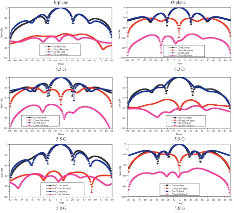
As shown in Fig. 11, an obvious improvement in the cross-polarization level, especially in the H
-plane, and a better asymmetry of radiation pattern in the E-plane can be achieved compared with
normally-fed array. To compare the performances of these two antenna arrays, the two prototypes were fabricated and shown in Fig. 12. The specific parameters of these two arrays are shown in Table 1. In Fact, a Balun is demanded to measure the differentially-fed antenna array. So a wideband balun,
(a) (b) (c)
Figure 12. Photos of the fabricated antenna prototype: (a) normally-fed antenna array, (b)
differentially-fed antenna array, (c) balun used for testing.
Cross Nor-feed Co Dif-feed Co Nor-feed Cross Dif-feed
Co Dif-feed Cross Dif-feed Cross Nor-feed Co Nor-feed
10 20 30 40 50 60 70 80 90
0
-20
-40
-60
-80
-90
Gain (dB)
Theta
-90 -80 -70 -60 -50 -40 -30 -20 -10 0
E-plane
5.3 G -10
-30
-50
-70
10 20 30 40 50 60 70 80 90
0
-20
-40
-60
-80
-90
Gain (dB)
Theta
-90 -80 -70 -60 -50 -40 -30 -20 -10 0
H-plane
5.3 G -10
-30
-50
Co Dif-feed Cross Nor-fed Cross Dif-feed Co Nor-feed
Co Dif-feed Cross Dif-feed Co Nor-feed Cross Nor-feed
Co Dif-feed Co Nor-feed Cross Dif-feed Cross Nor-feed
Co Dif-feed Co Nor-fed Cross Dif-feed Cross Nor-feed
10 20 30 40 50 60 70 80 90
-80
-90
Theta
-90 -80 -70 -60 -50 -40 -30 -20 -10 0
5.5 G -70
10 20 30 40 50 60 70 80 90
-20
-40
-60
-80
-90
Gain (dB)
Theta
-90 -80 -70 -60 -50 -40 -30 -20 -10 0
5.8 G -10
-30
-50
-70 0
10 20 30 40 50 60 70 80 90
-80
-90
Theta
-90 -80 -70 -60 -50 -40 -30 -20 -10 0
5.5 G -70
10 20 30 40 50 60 70 80 90
0
-20
-40
-60
-80
-90
Gain (dB)
Theta
-90 -80 -70 -60 -50 -40 -30 -20 -10 0
5.8 G -10
-30
-50
-70
Figure 13. The measured radiation patterns of two kinds of antenna arrays.
-40 -35 -30 -25 -20 -15 -10
Measured Simulated
Measured Simulated 0
-5
5.0 5.1 5.2 5.3 5.4 5.5 5.6 5.7 5.8 5.9 6.0 Freq (GHz)
S
(dB)11
5.0 5.1 5.2 5.3 5.4 5.5 5.6 5.7 5.8 5.9 6.0 Freq (GHz)
-40 -35 -30 -25 -20 -15 -10 0
-5
S
(dB)11
-45
(a) (b)
Figure 14. The measured and simulatedS11 of (a) normally-fed array and (b) differentially-fed array.
proposed in [13], from 3.6 to 10.7 GHz with a good balanced performance within 0.5 dB magnitude
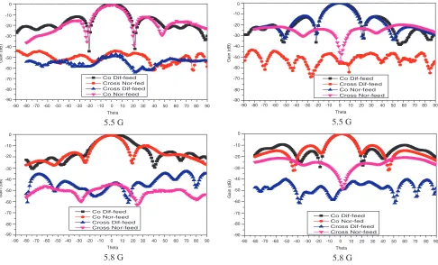
imbalance and less than 6◦ phase imbalance was used in the testing process. The test results of radiation
patterns of normally-fed and differentially-fed U-slot patch antenna arrays in theH-plane are compared
in Fig. 13. The measured patterns only show results from −90◦ to 90◦ due to limitation of the facility.
The measured and simulatedS11of normally-fed and differentially-fed arrays are shown in Fig. 14. The
4. CONCLUSION
In this paper, a single layer 4×4 U-slot patch antenna array based on differential feeds is proposed to
achieve wideband performance and low cross-polarization levels. The 4×4 array based on differential
feeds is measured by a wideband balun which includes the whole bandwidth of the array and compared with an array having the same structure but based on normal feed. The designed array has more than 12.4% (reflection coefficient lower 10 dB) measured impedance bandwidth with stable 18–19 dBi gain
across the band. A better asymmetry of radiation pattern in the E-plane and a lower than −45 dB
cross-polarization levels in theH-plane can be achieved compared with normally-fed array, which make
the array have a better performance in radiation pattern. Furthermore, this work is based on a single layer and differentially-fed design, which makes it simple and easily integrated with different devices directly without baluns.
REFERENCES
1. Lau, K. L., K. M. Luk, and K. F. Lee, “Wideband U-slot microstrip patch antenna array,” Inst.
Elect. Eng. Proc. — Microw. Antennas Propag., Vol. 148, No. 1, 41–44, 2001.
2. Liu, S., W. Wu, and D.-G. Fang, “Single-feed dual-layer dual-band E-shaped and U-slot patch
antenna for wireless communication application,” IEEE Antennas and Wireless Propagation
Letters, 2015.
3. Weigand, S., G. H. Pan, and J. T. Bernhard, “Analysis and design of broad-band single-layer
rectangular U-slot microstrip patch antennas,” IEEE Trans. Antennas Propag., Vol. 51, No. 3,
457–468, Mar. 2003.
4. Lau, K. L., K. M. Luk, and K. F. Lee, “Wideband U-slot microstrippatch antenna array,” Inst.
Elect. Eng. Proc. — Microw. Antenns Propag., Vol. 148, No. 1, 41–44, 2001.
5. Wang, H., X. B. Huang, and D. G. Fang, “A single layer wideband U-slot microstrip patch antenna
array,”IEEE Antennas and Wireless Propagation Letters, Vol. 7, 9–12.
6. Zhang, Y. P. and J. J. Wang, “Theory and analysis of differentiallydriven microstrip antennas,”
IEEE Trans. Antennas Propag., Vol. 54, No. 4, 1092–1099, 2006.
7. Wong, W. and Y. P. Zhang, “0.18-mm CMOS push-pull power amplifier with antenna in IC
package,” IEEE Microwave Wireless Comp. Lett., Vol. 14, No. 1, 13–15, 2004.
8. Abele, P., E. Ojefors, K. B. Schad, E. Sonmez, A. Trasser, J. Konle, and H. Schumacher, “Wafer level integration of a 24 GHz differential SiGe-MMIC oscillator with a patch antenna using BCB
as a dielectric layer,” Proc. 11th GAAS Symp., 419–422, Munich, Germany, 2003.
9. Xue, Q., X. Y. Zhang, and C.-H. K. Chin, “A novel differential-fed patch antenna,”Antennas and
Wireless Propagation Letters, Vol. 5, 471–474, 2006.
10. Brauner, T., R. Vogt, and W. Bachtold, “A differential active patch antenna element for array
applications,” IEEE T. Microw. Wireless Comp. Lett., Vol. 13, No. 4, 161–163, 2003.
11. Wang, D., K. B. Ng, C. H. Chan, and H. Wong, “A novel wideband differentially-fed higher-order
mode millimeter-wave patch antenna,” IEEE Trans. Antennas Propag., Vol. 63, No. 2, 466–473,
Feb. 2015.
12. Jin, H. Y., C.-C. Chang, H.-J. Li, and Q. Xue, “Differential-fed patch antenna arrays with low
cross polarization and wide bandwidths,” Antennas and Wireless Propagation Letters, Vol. 13,
1069–1072, 2014.
13. Lin, S. M., J. P. Wang, and G. Zhang, “A new compact ultra-wideband balun for printed balanced