9400
UNIVAC is a Registered Trademark of the Sperry Rand Corporation.
CONTENTS
1. INTRODUCTION
1.1. UNIVAC 9000 SERIES COMPUTER FAMILY 1.2. GROWTH AND COMPATIBILITY
1.3. SOFTWARE FEATURES 1.3.1. Modularity
1.3.2. Multiprogramming 1.4. COMMUNICATIONS
1.5. EQUIPMENT CONFIGURATIONS 2. SYSTEM HARDWARE
2.1. THE UNIVAC 9400 SYSTEM 2.2. CENTRAL PROCESSOR UNIT 2.2.1. Main Storage Characteristics 2.2.1.1. Addressing and Data Formats 2.2.1.2. Low
0
rder Sto rage2.2.1.3. Storage Protection
2.2.2. Control Section 2.2.3. Arithmetic Section 2.2.3.1. Fixed Point Arithmetic 2.2.3.2. Decimal Arithmetic 2.2.3.3. Logical Operations 2.2.4. Input! 0 utput Section 2.2.4.1. Multiplexer Channel 2.2.4.2. Selector Channel2.2.5. Interrupt Processing Control
2.3. UNIVAC 9400 INSTRUCTION REPERTOIRE 2.3.1. Supervisor Instruction Set
2.3.2. Standard I nstruction Set 2.3.3. Instruction Types
2.3.3.1. Register to Register Instructions (RR) 2.3.3.2. Register to Indexed Storage Instructions (RX) 2. 3. 3. 3. Reg i s t e r to S tor age Ins t r u c t ion s ( R S)
2.3.3.4. Storage and Immediate Operand Instructions (SI) 2.3.3.5. Storage to Storage Instructions (SSI)
2.3.3.6. Storage to Storage Instructions (SS2)
2,4.
CONTROL CON SOL E30
2.4.1.
Keyboard Assembly and Control30
2,4.2.
Printer Assembly and Control30
2.4.3.
Switches and Indicators31
2,5,
INPUT/OUTPUT DEVICES31
2.5.1.
Card Reader32
2.5.2.
Card Punch33
2.5.3.
High Speed Printer34
2,5.4.
Data Communication Subsystem35
25.4,1
Line Terminal Controller35
2.5,4.2.
Line Terminal35
2.5,4,3,
Communications Interface Unit36
2.5,4.4.
Asynchronous Timing Assembly37
2.5,4.5.
Synchronous Timing Assembly37
2.5,4.6.
Configurations37
2.5,5,
UNIVAC1004
or1005
Subsystem39
2.5,6,
UNIVAC9200
or9300
Subsystem41
2,5,7.
UNISERVO Magnetic Tape Subsystem42
2.5,7,
l. UNISERVO12/16
Magnetic Tape Subsystem42
2.5.7.1.1.
UNISERVO12
Tape Unit45
2.5.7.1.2.
UNISERVO16
Tape Unit47
2,5.7.2.
UNISERVO VI C Magnetic Tape Subsystem48
2,5,8,
UNIVAC8411
Direct Access Storage Subsystem50
3. PROGRAMMED SYSTEMS SUPPORT
52
3,1.
OPERATING SYSTEM52
3.
1, 1. Supervisor52
3. 1. 1.1.
M ul tiprogramm ing53
3, 1,
1. 2.
Interval Timer and Simulated Day Clock54
3.1. 1.1
Time Allocation54
3.1.1.4.
Shared Routine Coding54
3.1.1.5.
Operator Communication54
3.1.1.6.
Transient Area Management55
3.1.1.7,
Interrupt Handling55
3.1.1.8.
Input/Output Control System (IOCS)56
3.1.1.9.
Direct Access Auxiliary Storage56
3. L 2.
Data ivianagement57
3. 1.2 1
Sequential Access Method57
3.1.2.2.
Nonsequential Access Method57
3.1. 2.2.1.
Direct Access Method58
3.1.2.2,2.
Indexed Sequenti al Access Method58
3.1.3.
Job Control58
3.2. LANGUAGE PROCESSORS 3.2.1. Assembler
3.2.2. COBOL
3.2.2.1. COBOL Compilers 3.2.2.2. Tape Compiler
3.2.2.3. Direct Access Storage Compiler 3.2.3. FORTRAN
3.2.4. Report Program Generator (RPG) 3.3. SERVICE AND UTILITY ROUTINES 3.3.1. Sort and Merge
3.3.2. Library Services 3.3.3. Linkage Editor
3.3.4. Utility Programs and Program Testing Aids 3.4. SOFTWARE CONFIGURATOR
APPENDICES
A. UNIVAC 9400 SYSTEM INSTRUCTIONS
B. ASCI 1-8 AND EBCDIC CODE CHARTS
C. PRINTER CHARACTER SET
FIGURES
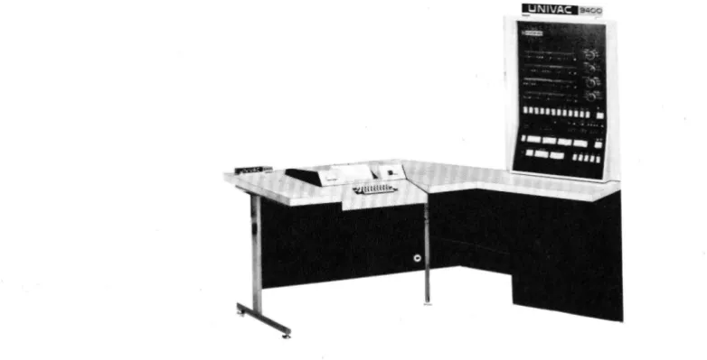
1-1. The UN IV AC 9400 System
1-2. UNIVAC 9400 Processor and Console Configuration 1-3. UNIVAC 9400 System Minimum Configuration (Tape System) 1-4. UNIVAC 9400 System Minimum Configuration (Disc System)
1-5. Typical UNIVAC 9400 System Configuration (Disc System with Tape) 1-6. Typical UNIVAC 9400 System Configuration (Disc System with Tape
and Communications) 2-1. Basic Instruction Format 2-2. UNIVAC 9400 System Console
2-3. UNIVAC 9400 Central Processor with Data Communication Subsystems
TABLES
2-1. Symbols Used to Describe Operand Formats 2-2. Line Terminal Characteristics
2-3. UNISERVO 12/16 Magnetic Tape Subsystem Characteristics 2-4. UNISERVO VI C Magnetic Tape Subsystem Characteristics
1. INTRODUCTION
1.1. UNIVAC 9000 SERIES COMPUTER FAMILY
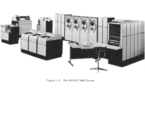
The UNIVAC 9000 Series is a computer family that embodies many bold, new design concepts in a unified and low cost line of data processing equipment. The UNIVAC 9200 computer is a small, card oriented data processing system with a basic internal storage capacity of 8,192 bytes. The 9200 System can be expanded to the higher performance card or tape oriented 9300 System. From this, it is easy to make the transition to the still more powerful tape or disc oriented UNIVAC 9400 System, shown in Figure 1-1, which has a basic storage capacity of 24,576 bytes with a cycle time of 600 nanoseconds. Internal stora ge for the 9400 Sys tern cons ists of a plated-wire memory as developed by Univac for the 9000 Series computers.
Equipment expa ns ions to large r s ys terns or diffe ren t configurations of the same sys tern are compatible within the 9000 Series. This highly desirable hardware compatibility also applies to software in the 9000 Series. Programming compatibility within the wide range of data processing capability offered by the 9000 Series allows maximum freedom for growth and expansion into larger equipment configurations.
The equipment and programming compatibility features of the UNIVAC 9000 Series computers allow the entire series to be thought of as essentially one large computer sys tern whose size and confi guration are adjus ta ble ove raw ide range of da ta process ing applications. From the user's point of view, this range of choice is the most economical because a system can always be selected to fit the needs of an installation. Costly time lags where the computing system can be ahead or behind the demands of the user are thereby eliminated.
The UNIVAC 9400 System offers speed, reliability, modularity, compactness, and, most significantly, economy to the user requiring random or sequential batch processing, or communications processing.
The operating system for the UNIVAC 9400 consists of a comprehensive set of program-ming aids, control programs and utility services. It is modular in design to fulfill a wide range of data processing requirements. The user may write programs in the common higher level programming languages, COBOL and FORTRAN. These higher level pro-gramming languages and the symbolic assembly language permit a choice of the language best suited to the application. Control programs provide for both random and sequential ba tch process in g, and com munica tion process ing. Data to be processed can be introduced to the sys tern from ei ther central or remote locations.
Conceptually, the approach to the system is the same for all users, regardless of the size of their system. The operating system is designed to provide (as far as possible) the same functions for all configurations. However, system performance is dependent upon the facilities available. In certain ins tances, the smaller sys terns may require additional passes over the data to obtain the same output that a more powerful system would produce in a single pass.
Computer applications in the UNIVAC 9400 System can be broadly classified as follows:
• Random and sequential batch processing
• Communications oriented processing
SYSTEM ORIENTATION Tape/disc
DATA ORGANIZATION 8-bit byte
BASIC INTE RNAL STORAGE 24,576 bytes
MAXIMUM INTERNAL STORAGE 131,072 bytes
MEMORY CYCLE TIME 600 nanoseconds/2 bytes
ADD (BINARY) INSTRUCTION TIME
(TWO 32-BIT WORDS) 6 microseconds
DECIMAL MULTIPLY AND DIVIDE
INSTRUCTIONS Standard
EDIT INSTRUCTION Standard
CARD READER 600 cpm
CARD PUNCH 200 cpm or 250 cpm
READ/PUNCH Optional
PRINTER 900 to 1100 Ipm
or
1200 to 1600 I pm
MAGNETIC TAPE RATE 34,160 bytes per second
to 192,000 bytes per second
NUMBER OF MULTIPLEXER CHANNELS 1
MULTIPLEXER CHANNEL RATE 85,000 bytes per second
NUMBER OF OPTIONAL SELECTOR CHANNELS 2
SELECTOR CHANNEL RATE 333,000 bytes per second
REGISTERS 16 for problem program functions
16 for Supervisor functions
DISC STORAGE 7.25 million bytes per drive
1.2. GROWTH AND COMPATIBILITY
The UNIVAC 9400 System hardware and software features surpass current standards. The features are at the disposal of the user to any extent he wishes. A basic system can be supplemented by many optional features to meet a wide variety of system needs.
The modular design of the UNIVAC 9400 System, coupled with its high speed main storage and I/O architecture, provides a dependable base for future extensions. Changes in business demands, applications, programming techniques, system configuration, or new input/output devices can be readily incorporated in the UNIVAC 9400 System. This architecture extends the usefulness of the initial planning, programming, and operational procedures used with the system.
The UNIVAC 9400 System is complemented by a line of direct access storage, magnetic tape, communications, punched card reading and punching, and high speed printing devices. Peripheral devices are available with different speeds, capacities, and
industry data compatibility to permit each user to select the most profitable combination for his application.
The availability of a high speed multiplexer channel enables many input/output devices to exchange data with the central processor at a rate of 85,000 bytes per second. Each device can transmit or accept data without degrading the operation of other devices. Two selector channels are available with the system to provide a combined data exchange capability of 666,000 bytes per second.
The UNIVAC 9400 Central Processor makes storage available on an incremental basis. Thus, each user can select a main storage capacity to best meet his specific requirements. Main storage can be expanded to 32K, 49K, 65K, 98K, and 131K bytes.
1. 3. SOFTWARE FEATURES
The principal objective of the UNIVAC 9400 Operating System is to make the full power of the computing system available to the user to solve his data processing tasks. Implicit in this objective is the need that the software system be consistent with the capabilities of a small- to medium-scale computing system. Overly sophisticated functions, which are of questionable value, have been omitted from the software.
The Supervisor control program is a part of the operating system that operates with problem programs to provide the control necessary for optimum utilization of the UNIVAC 9400 System hardware and software. By use of the Supervisor, the hardware and software systems are effectively coordinated to satisfy the requirements of a growing number of diversified applications. Problems are handled directly and promptly with as little internal bookkeeping as possible without compromising the integrity of the computing system.
1.3.1. Modularity
Functional modularity has been employed in the design of the Supervisor to ensure its adaptation to a wide range of data processing applications. The user can tailor the Supervisor to his particular applications by parameter selection and specification of the various functional modules at systems generation time.
1.3.2. Multiprogramming
Utilization of central processor time is maximized by multiprogramming. A Supervisor can be generated to control from one to five problem programs. In this environment,
problem programs are processed concurrently in the computing system. In addition to
problem programs, many of the Supe rvisor functions are desi gned as autonomous activi ties capa ble of being processed as independent programs.
The multiprogramming technique employed by the Supervisor involves the distribution of processing time to independent programs based on program priorities, time allo-cations, and input/output equipment utilization. Consideration of these factors by the Supervisor assures the user that the distribution of processing time is efficient and equitable.
1.4. COMMUNICA TIONS
The UNIVAC 9400 System can be used for communications oriented data processing through the use of a UNIVAC Data Communication subsystem (DCS) and the commu-nications adapter. Each communication subsystem must be attached to the UNIVAC 9400 Central Processor by means of one of the eight subchannels provided in the standard multiplexer channe 1. The com munica tion configurations provide for any number of simplex line positions up to a maximum of 64 input and 64 output line terminals. In the duplex mode (two directional) a total of 64 line terminals can be
accomm oda ted.
The accuracy of transmission can be controlled through an optional parity check on all communicated data. Either odd or even parity check can be performed for each character in a message to the central processor. Similarly, odd or even parity can be generated for each character transmitted. In addition, a longitudinal redundancy
check may be performed for each input message and generated for each output message.
The Data Communication Subsystem is compatible with Data-Phone* Service, TWX Networks, Telex**, and Telpak*** C.
1.5. EQUIPMENT CONFIGURATIONS
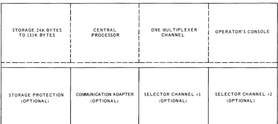
The following diagrams (Figures 1-2 to 1-6) illustrate some of the system config-urations that are available on the UNIVAC 9400 System. Figure 1-2 shows the UNIVAC 9400 Processor and console configuration.
I I
I
I
II
I
I
I
I
I
I
STORAGE 24K BYTES I CENTRAL
I
ONE MULTIPLEXERI
OPERATOR'S CONSOLE TO l3lK BYTES I PROCESSORI
CHANNEL II
I
II
I
I
I
I
I I
f - - - ___ ...l- _ _ _ _ _ _ _ _ _ --1- _ _ _ _ _ _ _ _ _ ~ __________
STORAGE PROTECTION COMMUNICATION ADAPTER SELECTOR CHANNEL ttl SELECTOR CHANNEL tt2
(OPTIONAL) (OPTIONAL) (OPTIONAL) (OPTIONAL)
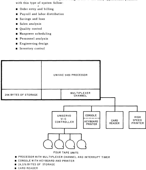
The system configuration shown in Figure 1-3 provides a convenient transition from smaller tape systems such as the UNIVAC 9300. This system is suitable for both scientific and business data processing. A few of the many applications possible with this type of system follow:
• Order entry and billing • Payroll and labor distribution • Savings and loan
• Sales ana lysis • Quality control • Manpower scheduling • Personnel analysis • Engineering design • Inventory control
24K BYTES OF STORAGE
UNIVAC 9400 PROCESSOR
MUL TIPLEXER CHANNEL
UNISERVO VI C CONTROLLER
FOUR TAPE UNITS
CONSOLE KEYBOARD
PRINTER
CARD READER
• PROCESSOR WITH MULTIPLEXER CHANNEL AND INTERRUPT TIMER • CONSOLE WITH KEYBOARD AND PRINTER
• 24,576 BYTES OF STORAGE • CARD READER
• HIGH SPEED PRINTER
• UNISERVO VI C CONTROLLER WITH FOUR TAPE UNITS
Figure 7-3. UNIVAC 9400 System Basic Configuration (Tape System)
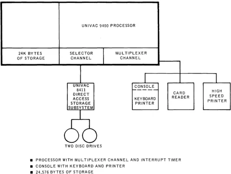
The system configuration shown in Figure 1-4 provides a convenient transition from smaller disc-pack oriented systems. This system, as a result of the auxiliary disc storage, is suited for both scientific and business data processing. A few of the many applica tions possible with this sys tern follow:
• Billing and accounts recei va ble • Quality control
• Savings and loan • Personnel analysis
• Statistical analysis • Engineering design
• Payroll and labor distribu tion • Inventory control • Production control
Small files can be more efficiently referenced and maintained using the direct access (disc) storage. Since program libraries, as well as frequently used files, can always
be available on disc, this system can be used for short irregularly scheduled runs concurrently with other processing.
UNIVAC 9400 PROCESSOR
24K BYTES SELECTOR MUL TIPLEXER
OF STORAGE CHANNEL CHANNEL
I
I
UNIVAC CONSOLE
8411 ~---- HIGH
DIRECT CARD
ACCESS KEYBOARD READER SPEED
STORAGE PRINTER PRINTER
SUBSYSTEM
66
TWO DISC DRIVES• PROCESSOR WITH MULTIPLEXER CHANNEL AND INTERRUPT TIMER • CONSOLE WITH KEYBOARD AND PRINTER
• 24,576 BYTES OF STORAGE • CARD READER
• HIGH SPEED PRINTER
The system configuration shown in Figure 1-5 combines the advantages of the tape and the disc systems. A few of the many applications possible with this system follow:
• Billing and accounts receivable • Sales statistics
• Insurance • Production control
• Pension • Engineering design
• Order en try • Inventory control
• Personnel statistics
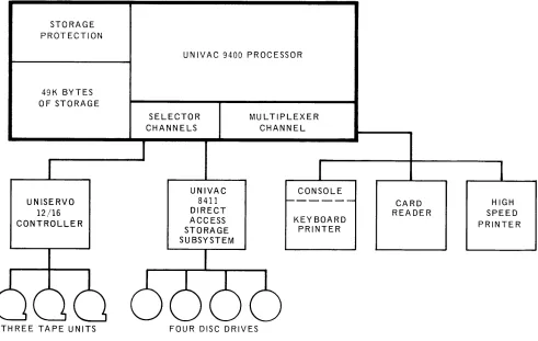
The broad flexibility of disc stored program libraries and control stream technique provide software and system organization that has been previously available only in the largest computer systems. The tape and disc combinations are well suited for applications where there are large master files having a high percentage of updates each cycle. Also, the use of tapes saves disc-pack cost and provides a fast method of sequential processing. The discs provide program overlays, table storage, small file storage, and the flexibility of the disc oriented operating system.
STORAGE PROTECTION
49K BYTES OF STORAGE
UNISERVO 12/16 CONTROLLER
THREE TAPE UNITS
UNIVAC 9400 PROCESSOR
SELECTOR CHANNELS
UNIVAC 8411 DIRECT ACCESS STORAGE SUBSYSTEM
MULTIPLEXER CHANNEL
CONSOLE
-KEY BOARD PRINTER
FOUR DISC DRIVES
CARD READER
• PROCESSOR WITH MULTIPLEXER CHANNEL AND INTERRUPT TIMER • CONSOLE WITH KEYBOARD AND PRINTER
• 49,152 BYTES OF STORAGE WITH STORAGE PROTECTION • CARD READER
• HIGH SPEED PRINTER
• UNISERVO 12/16 CONTROLLER WITH THREE TAPE UNITS
• UNIVAC 8411 DIRECT ACCESS STORAGE SUBSYSTEM WITH FOUR DISC DRIVES
Figure 7 -5. Typical UNIVAC 9400 System Configuration
UNISERVO 12/16 CONTROLLER
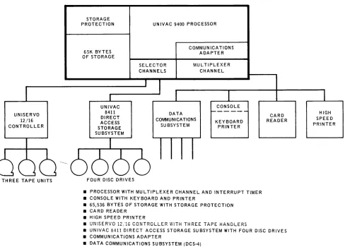
The sys tern configuration show n in Figure 1-6 provides communication capa bili ty in addition to the capabilities of the disc and tape system illustrated in Figure 1-5. A few of the many applications provided by adding the communications facility follow:
• Inquiry systems
• Remote transaction processing • Data collection from remote terminals
The multiprogramming capabilities of the system permit the communication applications to operate concurrently with batch programs initiated at the system site.
STORAGE PROTECTION
65K BYTES OF STORAGE
UNIVAC 8411 DIRECT ACCESS STORAGE SUBSYSTEM
UNIVAC 9400 PROCESSOR
SELECTOR CHANNELS
COMMUNICATIONS ADAPTER
MU L TIPLEXER CHANNEL
CONSOLE DATA
COMMUNICATIONS
SU BSYSTEM KEYBOARD PRINTER
CARD READER
HIGH SPEED PRINTER
THREE TAPE UNITS FOUR DISC DRIVES
• PROCESSOR WITH MULTIPLEXER CHANNEL AND INTERRUPT TIMER • CONSOLE WITH KEYBOARD AND PRINTER
• 65,536 BYTES OF STORAGE WITH STORAGE PROTECTION • CARD READER
• HIGH SPEED PRINTER
• UNISERVO 12/16 CONTROLLER WITH THREE TAPE HANDLERS
• UNIVAC 8411 DIRECT ACCESS STORAGE SUBSYSTEM WITH FOUR DISC DRIVES • COMMUNICATIONS ADAPTER
• DATA COMMUNICATIONS SUBSYSTEM (DCS-4)
2. SYSTEM
HARDWARE
2.1. TH E UNIVAC 9400 SYSTEM
The UNIVAC 9400 System was designed to be a medium cost, high performance, system with data processing and communication capability that is well within the reach of the majority of data processing users, and in which no compromise is made with operating potential. This design goal has been reached. In the case of the processor storage and circuitry, the resulting high speed permits the UNIVAC 9400 System to compete favorably in the performance of any conventional data processing program.
2.2. CENTRAL PROCESSOR UNIT
Main s tora ge, control, arithmetic, and input/ ou tput sections comprise the major parts of the control proce'ssor. A description of these parts are described in the following para graphs.
2.2.1. Main Stora ge Characteris tics
2.2.1.1. Addressing and Data Formats
Each eight-bit byte of main storage can be accessed by the problem program. These bytes are addressed consecutively from 0 through a maximum of 131,071-Bytes may be accessed separately or in groups. The address of a group of bytes is addressed by the leftmost byte of the group. The bits in a byte are also numbered from left to right starting with zero.
o
7Ha lfw ord forma ts cons is t of two consecutive bytes.
Halfword
o
7 8 15Fullword formats consist of four consecutive bytes.
Fullword
o
7 8 1516 2324 31Variable data formats consist of a variable number of consecutive bytes.
Variable Data
Format
o
7First Byte
o
7Last Byte
Fixed length fields, such as halfwords and fullwords, have integral boundaries. Fixed length fields m us t be loaded in to main stora ge so that the address is evenly divisible by the field length (in bytes). Thus, a halfword must have an address that is a multiple of two and a fullword must have an address that is a multiple of four.
2.2.1.2. Low Order Storage
The low order 512 bytes of main storage have been reserved to contain specific operating information. The data stored in these locations is accessed by the hard-ware and the operating system during the execution of the appropriate functions. The operating system provides for loading and protecting the appropriate data in thes e loca tions.
2.2.1.3. Storage Protection
Program protection in a multiprogrammed environment is achieved by the write protection feature. Write protection is controlled through the use of the Limits Register, which limits the storage area that anyone program can access for storage of data. The Limits Register is under control of the Supervisor which loads tk.! address limits of the particular program in operation. An address exception inter-rupt is generated whenever a write order attempts to address a location outside the bounds of the Limits Register.
2.2.2. Control Section
The control section con troIs the sequence in which instructions are executed, and it interprets and controls the execution of each individual instruction. The cycling of main storage is initiated by this section. All of the hardware aspects of interrupt handling, error checking, and protection are performed by the control section. The control section also maintains the program address location counter and provides for the different processor modes of opera tion.
The central processor can reference two sets of 16 general purpose registers. Both sets are contained in low order storage. One set is used by the Supervisor and the other set is used by problem programs. This design greatly reduces the interrupt processing time overhead required when only a single set of general registers is used. Thus, when the processing mode is changed between problem program and Supervisor modes, the foilow in g steps required in sin gle regis ter s ys terns are unnecessary.
(1) Store the contents of problem program registers. (2) Load the executive routine data into the registers.
(3) Store the executive routine data.
(4) Reload the problem data back into the registers.
2.2.3. A ri thm etic Section
The arithmetic section performs all data manipula tions including logical and numerical arithmetic, data comparisons, and shifting. This section also performs single or double indexing of operand addresses. The adder in this section performs arithmetic in twos complement form. There are three classes of arithmetic opera tions as follows:
2.2.3.1. Fixed Point Arithmetic
A fixed point arithmetic operand can be either a 32-bit word or a 16-bit halfword. When pos sible, 16-bi t operands should be specified to conse rve s tora ge. The sign of a fixed point operand is always the leftmos t bit of the operand The following figures illustrate the format of halfword and fullword fixed binary values:
Halfword
Integer
Fullword
Integer
When a halfword fixed point number is called from storage, it is always expanded to a right justified fullword; the sign is extended to the left.
2.2.3.2. Decimal Arithmetic
Decimal nu m ber fie Ids ca n be variable in len gth and can exis t in two formats; unpacked decimal numbers and packed decimal numbers. Decimal operations including add, subtract, multiply, and divide, can be performed only on packed dec imal num bers. Ins tructions are provided for con verting decimal numbers from unpacked to packed and from packed to unpacked forma t.
In the unpacked decimal format, each byte contains one digit of the number. The byte is divided into two equal fields, a zone field and a digit field. A zone value IS rep!"esef!ted if! the most significant four bits, arid the digit is represented in the least significant four bits. The zone portion of the least significant byte specifies the sign of the number. The unpac ked forma t m us t be used when da ta is to be process ed by ce rtain I/O devices such as the prin te r. The forma t of a three -digi t number is shown below:
,
II I
ZONE: DIGIT ZONE: DIGIT
0 7 8 15
Byte Byte
t
,
SIGN I1
16 Byte
DIGIT 23
In packed format, each byte contains two digits. The least significant four bits of the least significant byte provides the sign of the number. Packed decimal format is used for all decimal arithmetic operations. The format of a five-digit number is shown below:
I I
DIGIT: DIGIT DIGIT: DIGIT
I
0 7 8 15
Byte Byte
I
DIGIT:
16 Byte
SIGN 23
Packed Decimal Number
Decimal numbers (0 through 9) are represented in the four bit binary coded decimal form (0000 through 1001). The codes 1010 through 1111 are used for sign codes. The binary values 1011 and 1101 represent a minus sign and the binary values 1010, 1100, 1110 and 1111 represent a plus sign. This assignment of sign codes permits the use of either of two conventions: American Standard (ASCII) expanded to eight bits or Extended Binary Coded Decimal (EBCDIC). The codes 1010 (plus) and 1011 (minus) are used in ASCII; the codes 1100 (plus) and 1101 (minus) are used in EBCDIC. A control bit in the Program Status Word determines whether the system is to operate in the ASCII or the EBCDIC mode.
2.2.3.3. Logical Operations
Logical operations such as comparing, translating, editing, bit setting, and bit tes tin g a re performed by the a ri thmetic section. Logica 1 operation s ca n be per-formed on fixed length operands and variable length operands. Logical operations on fixed length operands are performed in the registers; logical operations on va ria ble length operands are performed in main stora ge. The ins truction format determines whether the logical operation is to be performed in main storage or in a register.
2.2.4. Input/Output Section
The inpu t/ ou tpu t (I/O) section of the UNIVAC 9400 Central Processor initia tes, directs, and monitors the transfer of data between storage and the peripheral sub-systems. After an I/O instruction has been transferred to the control unit from the control section, the data transfer is performed concurrently with other central process or functions.
The I/O section consists of the input/output channels and the standard UNIVAC 9000 Series I/O Interface which connects channels with the unit controllers. This interface is identical for all the I/O control units; it has been designed for use with all of the available peripheral devices, as well as for future devices.
Two selector channels are available on the UNIVAC 9400 System in addition to the multiplexer channel.
2.2.4.1. Multiplexer Channel
Up to eight I/O control units can be connected to the multiplexer channel by means of the s u bcha nne Is; thes e ca n be any combination of standard con tro1 un its or Data Communications Subsystems (DCS). Standard control units can handle up to a maximum of 16 devices each depending upon the subsystem selected. Each DCS can (depending on the type) accommodate up to 32 simplex communication lines, with a maximum of four control units permitted allowing 128 simplex lines.
The Subchanne1 Control Word provides the address of the Buffer Control Word, and the Buffer Control Words provide controlling information needed by the I/O control units to transfer data to or from the central processor. The Subchanne1 Control Words for all subchanne1s are located in low order main storage. The Buffer Control Words can be located anywhere in main storage. A separate Subchannel Control Word is used for each of the eight subchannels associated with the multiplexer cha nne 1. If c omm unica tions devices have been included in the configura tion, the re is a Subchanne1 Control Word for each communication line. The existence of a separate Subchannel Control Word for each standard control unit and one for each communication line permits all of the low speed devices connected to the multi-plexer channel to operate concurrently. Each low speed device on the multimulti-plexer channel sends its eight-bit address over the channel prior to the transfer of each data byte. This device address causes the Subchanne1 Control Word and the Buffer Control Word to be selected from storage and placed in the Multiplexer Channel Register. This then directs the data byte into or out of the proper main storage loca tion. Thus, data trans fers are multiplexed when the Subchanne 1 Control Word and the associated Buffer Control Word re 1a ted to the appropriate device is specified for each byte transferred.
Examples of low speed devices are printers, card readers, card punches, remote communication devices, I/O subsystems such as the UNIVAC 1004 or 1005 Sub-system, and the UNIVAC 9200 or 9300 Subsystem.
2.2.4.2. Selector Channel
Two selector channels can be added as options to the basic configuration.
High speed devices, such as UNISERVO 12 and UNISERVO 16 Magnetic Tape Units and UNIVAC 8411 Disc Storage Drives may only be connected to the selector channels.
Eight standard control units may be attached to each selector channel. Up to 16 I/O devices can be attached to each of the eight control units depending on the particular subsystem selected.
2.2.5. Interrupt Processing Control
The UNIVAC 9400 System contains a very efficient interrupt system that makes it a highly capable comm unica tions s ys tern. The UNI VA C 9400 Interrupt Sys tern provides the means by which the central processor changes from the problem pro~
gram state to privileged or supervisor state. The seven types of interrupt employed in the UNIVA C 9400 Sys tern are lis ted below in order of priori ty:
• Supervisor Call Interrupt - This interrupt results from the execution of a super-visor ca11 instruction. Status information provides the operating system with a link to parameter information in the ca11ing program.
• Program Interrupt - This interrupt occurs when one of the fo11owing exceptions are recognized by the central processor.
- Illegal operation code.
- Privileged operation instruction encountered while the processor is in the problem state.
Storage Protection - attempting to write data outside the bounds of the Limits Register.
Addressing Exception state.
reference to low order storage while in the problem
Specifica tion Exception ~ in te gral boundary reference error. Binary Arithmetic Overflow.
Decimal Arithmetic Overflow.
• Timer Interrupt - This interrupt is caused when the millisecond timer storage is decremented to zero.
• Selector Channell Interrupt - This interrupt occurs when an interrupt condition has been generated on Selector Channell by a device.
• Selector Channel 2 Interrupt - This interrupt occurs when an interrupt condition has been generated on Selector Channel 2 by a device.
• Shared Multiplexer Channel Interrupt - This interrupt occurs when an interrupt condition has been generated on a shared multiplexer channel. The status is stored in the appropriate Subchannel Control Word.
2.3. UNIVAC 9400 INSTRUCTION REPERTOIRE
The power and flexibility of the UNIVAC 9400 System is reflected in the instruction repertoire and execution times. The full repertoire includes 67 instructions, many of which offer several optional variations. The instruction set is supplemented by an input/output device instruction which controls each of the possible peripheral devices.
The UNIVAC 9400 instructions fall into two functional ca tegories:
• Supervisor
• Standard
2.3.1. Supervisor Instruction Set
The Supervisor (privileged) instruction set is used primarily by the software operating system when operating in the supervisory state. In this state, all instructions
(Supervisor and standard) are valid and can be executed. The privileged general registers are selected and low order storage can be addressed. Instructions in the Supervisor set cannot be executed in a problem program.
2.3.2. Standard Instruction Set
The standard (nonprivileged) instruction set is used to write programs for operation in the problem state (applica tion and data processin g programs). In this s ta te, the Supervisor (privileged) instructions are invalid, the problem set of general registers is selected, and low order storage cannot be addressed.
The standard ins truction set provides ins tructions to process fixed len gth binary num bers, packed a nd unpacked decimal num bers, and alphabetical characters. Da ta may be transferred between main storage and the problem set of general registers and from storage to storage. The operations of shifting, branching, and logical functions are also included.
2.3.3. Instruction Types
Instructions can be either two, four, or six bytes in length. In a two byte or halfword instruction, only registers are referenced. A four byte or two halfword instruction references main storage once. A six byte or three halfword instruction references main storage twice. All instructions must be located in storage on halfword bound-aries, that is, have an even address. The six instruction types are:
• RR = a register to register operation
• RX = a register and indexed storage operation • RS = a register and storage operation
• SI = a storage and immediate operand operation
• SS1 = a storage to storage operation (256 byte maximum length) • SS2 = a storage to storage operation (16 byte maximum length)
2.3.3.1. Register to Register Instructions (RR)
The RR instructions are two bytes in length and are used primarily to process data between registers. The maximum data operand that can be handled is a full-word of 32 bits; the fullfull-word mayor may not be a signed binary number.
In this format, there are 14 instructions:
RR Ins tructions Mnemonic OP Codes
Add AND
Branch and Link Branch on Condition Branch on Count Compare
Compare Logical Exclusive OR Load
Load and Tes t OR
Set Program Mask Su btract
Supervisor Call
AR
NR
BALR BCR BCTR CR CLRXR
LR LTR OR SPM SR SVC
The source code forma ts of the RR ins tructions are:
OP R1
OP R 1 , R2 OP
OP M1 , R2
where:
•
OP is the mnemonic operation code.•
Rl is an expression representing a register as•
R2 is a n express ion representing a register as•
is actual data expressed in bits to be used•
Ml is a four bit data mask used in testing.operand 1.
operand 2.
The object codes formed by these codes are:
OP CODE
o
7 8OP CODE Rl R2
0 7 8 11 12 15
OP CODE Ml R2
2.3.3.2. Register to Indexed Storage Instructions (RX)
The RX instructions are four bytes in length and are used primarily to process data between registers and indexed storage. The maximum data operand that can be handled is a fullword of 32 bits; the fullword mayor may not be a signed binary number.
In this format, there are 20 instructions:
RX Instructions Mnemonic OP Codes
Add A
Add Halfword AH
AND N
Branch and Link BAL
Branch on Condition BC
Branch on Count BCT
Compare C
Compare Halfword CH
Com pare Logica 1 CL
Exclusive OR
x
Insert Character IC
Load L
Load Address LA
Load Halfword
LH
OR
o
Store ST
Store Character STC
Store Halfword STH
Su btract S
Subtract Halfword SH
The source code formats of the RX instructions are:
OP R1 , D 2(X2 , B 2)
where:
•
OP is the mnemonic operation code.•
R1 is an expression representing a register as operand 1.•
M1 is a four bit data mask used in testing.•
°2
is an expression designating the displacement value of operand 2.•
X2
is an expression designating a register whose contents is used to indexthe displacement and base address of operand 2.
is an expression designating a register whose contents is added to the displacement va lue to form the effective address of operand 2.
The object codes formed by these source codes are:
OP CODE R1 X2 B2 O2
0 7 8 11 12 15 16 19 20 31
OP CODE Ml X2 B2 O2
0 7 8 11 12 15 16 19 20 31
The effective address of operand 2 is formed by adding the contents of the base register B2 to the displacement value D2 ; this mayor may not be modified by adding the contents of index register X2'
2.3.3.3. Register to Storage Instructions (RS)
The RS instructions are four bytes in length and are used to perform multiple register storage and shift operations.
In this forma t, there are five instructions:
RS Instructions Mnemonic OP Codes
Load Limi ts Register (privileged instruction) LLR
Load Multiple LM
Shift Left Single Logical SLL
Shift Right Single Logical SRL
Store Multiple STM
The source code formats of the RS instructions are:
where:
• OP is the mnemonic operation code .
is an expression representing a register as operand 1, or a register which is the first register of a multiregister group.
is an expression representing a register which is the last register of a multiregister group.
is a n express ion designating the dis placement value of operand 2.
is an expression designating a register whose contents is added to the displacement value to form the effective address of operand 2.
The object codes formed by these source codes are:
31
OP CODE Rl R3 B2 D2
0 7 8 11 12 15 16 19 20 31
OP CODE
7 16 19 20 31
2.3.3.4. Storage and Immediate Operand Instructions (SI)
The SI instructions are four bytes in length and are used to provide control data for operation of the processor and peripherals. There are eleven instructions in this forma t di vided in to three ca tegorie s: Logica 1, P roce ssor Control, and In put! Output Control.
SI Instructions Mnemonic OP Codes
Logical
Add Immediate AI
Compare Logical Immediate CLI
Move Immediate Data MVI
AND Immediate Data NI
OR Immediate Data 01
TEST Under Mask TM
Exclusive OR XI
Processor Control
Halt and Proceed (pri vileged ins truction) HPR
LOA D Program State Word (privileged ins truction) LPSW
SE T Sys tern Mas k (pri vile ged instruction) SSM
Input/Ouput Control
START I/O (privileged instruction) SIO
The source code formats of the SI instructions are:
OP D 1(B 1)
OP D1(B 1),I 2
where:
• OP is the mnemonic operation code.
• D1 is an expression designating the displacement value of operand 1.
• B1 is an expression designating a register whose contents is added to the displacement value to form the ef£ecti ve address of operand l.
The object codes formed by these Source codes are:
OP CODE
o
7 3112
The effective address of operand 1 is formed by adding the contents of the base register (B1) to the displacement value (01),
2.3.3.5. Storage to Storage Instructions (SSl)
The SSl instructions are six bytes in length and are used to process data in storage where the operands are equal in length. The maximum operand may be 256 bytes in length.
In this format, there are nine instructions:
SS 1 Instructions
Compare Logical Character
Edit
Move Characters
Move Numerics
Move Zones
AND Characters
OR Characters
Translate Exclusive OR
Mnemonic OP Codes CLC
ED
MVC
MVN
MVZ
NC
OC
TR
XC
where:
•
OP•
Dl•
L•
Bl•
D2is the mnemonic operation code.
is an expression designating the displacement value of operand 1.
is a value which states the length of both operand 1 and operand 2.
is an expression designating a register whose contents is added to the displacement Dl to form the effective address of operand 1.
is an expression designating the displacement value of operand 2.
•
B2 is an expression designating a register whose contents is added to thedisplacement D2 to form the effective address of operand 2.
The object code formed by this source code is:
OP CODE L B1 D1 B2 D2
0 7 8 15 16 19 20 31 32 35 36 47
The effective address ot operand 1 is formed by adding the contents of base register Bl to the displacement value Dl and the effective address of operand 2 is formed by adding the contents of base register B2 to the displacement value D 2 .
2.3.3.6. Storage to Storage Instructions (SS2)
The SS2 instructions are six bytes in length and are used to process data in storage where the operands are unequal in length. The maximum operand can be 16 bytes in length.
In this format, there are nine instructions:
SS2 Instructions Mnemonic OP Codes
Add Packed Decimal AP
Compare Packed Decimal CP
Divide Packed Decimal DP
Multiply Packed Decimal MP
Move With Offset MVO
Pack PACK
Subtract Packed Decimal SP
Unpack UNPK
The source code format for these instructions is:
where:
• OP
is the mnemonic operation code.is an expression designating the displacement value of operand 1.
is a value designating the length of operand 1.
is an expression designating a register whose contents is added to the displacement D1 to form the effective address of operand 1.
is an expression designating the displacement value of operand 2.
is a value designating the length of operand 2.
is an expression designating a register whose contents is added to the displacement D2 to form the effective address of operand 2.
The object code formed by this source code is:
OP CODE Ll L2 B1 D1 B2 D2
a
7 8 11 12 15 16 19 20 31 32 35 36The effective address of operand 1 is formed by adding the contents of base register B1 to the displacement value D1 and the effective address of operand
47
2 is formed by adding the contents of base register B2 to the displacement value D2 ·
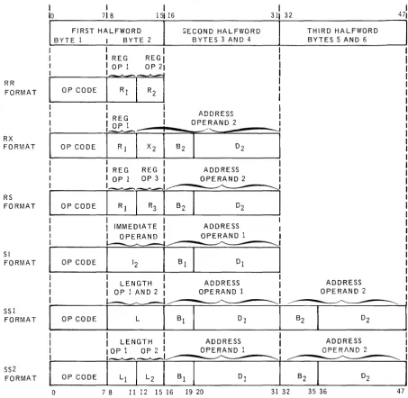
2.3.3.7. Instruction Formats
The basic instruction formats are illus trated in Figure 2-1 and an explanation of the symbols used is provided in Table 2-1. The subscripts 1, 2, and 3 indicate that the given field refers to operand 1, operand 2, or operand 3 respectively. In general, data are processed from operand 2 to operand 1, with the result often replacing the original contents of operand 1. Operand 3 is a special notation explained in the RS type instruction in 2.3.3.3.
Most instructions are two halfwords in length, however, the RR instructions require only one halfword and therefore are executed faster. The SS1 and SS2 instructions use three halfwords and require more execution time, which is dependent upon the length of the data processed by the instruction.
RR FORMAT RX FORMAT RS FORMAT SI FORMAT SSI FORMAT SS2 FORMAT 1 10 I 718
FIRST HALFWORD BYTE 1 I BYTE 2
I I
I I REG REGI
I IOPl OP21
j
OP CODEi~[;l
I
I REG I
OP CODE
I
O~ll
[X21
I
I REG REG I OP 1 OP 3 I
OP CODE
i-:r:-I
I
I IMMEDIATE
I OPERAND I
OPCOOE
n
I
I
LENGTHI
OP 1 AND 2 I~
OP CODE
I
L
I
I
I
LENGTH IOPl OP2 IOP CODE
SECOND HALFWORD BYTES 3 AND 4
ADDRESS OPERAND 2
ADDRESS OPERAND 2
ADDRESS OPERAND 1
ADDRESS OPERAND 1
ADDRESS OPERAND 1
o
7 8 11 12 15 16 19 20Figure 2-1. Basic instruction Formats
I
311 32
l
B2 31 32
THIRD HALFWORD BYTES 5 AND 6
ADDRESS OPERAND 2
ADDRESS OPERI\ND 2
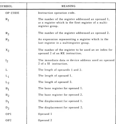
The entries in the following table explain the meaning of the symbols used in describing the instruction formats in Figure 2-1.
SYMBOL
OP CODE
L
OP2
MEANING
Instruction operation code.
The number of the register addressed as operand 1, or a register which is the first register of a multi-register group.
The number of the register addressed as operand 2.
An expression representing a register which is the last register in a multiregister group.
The number of the register to be used as an index for operand 2 of an RX instruction.
The immediate data or device address used as operand 2 of a SI instruction.
The length of ope ra nds 1 and 2.
The length of operand 1.
The length of operand 2.
The base register for operand 1.
The base register for operand 2.
The displacement for operand 1.
The displacement for operand 2.
Operand 1
Operand 2
The UNIVAC 9400 System console is a means for communication between the operator and operating system. The console consists of a keyboard, printer, switches, and indicators, which are housed in a platform attached to the processor as shown in Figure 2-2. The associated control and interface I/O logic is housed in the processor.
Figure 2-2. UNIVAC 9400 System Console
2.4.1. Keyboard Assembly and Control
The keyboard resembles a standard typewriter keyboard. This assembly consists of 46 keyin switches and a core logic encoding network. Pressing one of the keyin switches causes an EBCDIC coded character and a sprocket pulse to be transmitted in bit parallel from the encoding network to the keyboard control logic interface.
The keyboard assembly and control is activat~d by a read command from the UNIVAC 9400 Processor. This command is requested by pressing the ATTEN TION switch located next to the printer, and it remains active throughout the input operation. During the input operation the printing of each character signifies that the particular character has been stored. The input opera tion can be terminated at any point by pressing the End-of-Message key ( (EOM STOP}). If an incorrect character is typed, pressing the ERROR switch located next to the printer also terminates the input operation.
2.4.2. Printer Assembly and Control
The UNIVAC 9400 System printer is capable of printing 10 characters per second on
8-1
/
2
inch friction feed roll paper. Information in EBCDIC code from the processor is converted to ASCI I code by the printer control logic and transmitted to the printer assembly in a bit serial sequence.2.4.3. Switches and Indicators
There are four sw itches and indica tors located on the console (two on each side of the printer). These controls and ind icators permit the operator to initiate or terminate a message to the operating system, and to control printer paper movement.
The function of each of these is summarized as follows:
Swi tch/Indica tor
PAPER FEED (Sw.) (white)
ATTENTION (Sw. and Ind.) (white)
ERROR (Sw.) (white)
READ (Ind.) (green)
2.S. INPUT/OUTPUT DEVICES
Function
This momentary contact switch activates the paper feed mechanism when pressed. Paper is fed continuously as long as the switch is pressed.
This momentary contact switch is used to solicit a read command. The indicator is is extinguished when the attention status is received by the processor.
This momentary contact switch is used to terminate the input operation, and signals the processor that there was an incorrect character typed in from the keyboard.
This indicator is lit to indicate that the console is in the input mode.
A full line of peripheral devices and subsystems are available for use with the UNIVAC 9400 System. These devices and subsystems are:
• Card Reader
• Card Punch
• High Speed Printer
• Data Communications Subsystem
• UNIVAC 1004 or 100S Subsystem
• UNI VAC 9200 or 9300 Subsystem
• UNISERVO Magnetic Tape Subsystems
• UNIVAC 8411 Direct Access Storage Subsystem
2.5.1. Card Reader
C
H
A
RAe
T
E
'
R 1ST I
C S
CARD READING SPEED
INPUT HOPPER CAP,A.CITY
OUTPUT STACKER CAPACITY
READ MODES
I/O CHANNELS
OPTIONAL FEATURES
600 cpm
1200 cards
1500 cards
Image mode - 160 6-bit characters per card
E BC D IC - 80 characters per card
1 subchannel
51- or 66-column short card feeds
The card reader operates at a rate of 600 cards per minute on a column by column basis. The read check feature is standard to ensure correct input. Information read from the card is transferred to the processor in either image mode or EBCDIC mode.
2.5.2. Card Punch
CHARACTERISTICS
CARD PUNCHING SPEED
INPUT HOPPER CAPACITY
OUTPUT STACKER CAPACITY
PUNCH MODES
I/O CHANNELS
OPTIONAL FEATURE
200 or 250 cpm
1000 card~
2 stackers - 1000 cards per stacker
Image mode - 160 6-bit characters per card
Translate mode - 80 characters per card
1 subchannel
Read before punching
The card punch operates at a rate of 200 or 250 cards per minute on a row by row basis (12 punching positions per card). Standard features include processing 80-column cards in either punched card code or main storage image code modes. Output cards can be directed to either stacker under control of the program.
The card punch includes a selfcontained control unit and synchronizer which regulates the flow of data and control signals to and from the punch mechanism. This control unit is attached to the UNIVAC 9400 Central Processor by means of one of the eight subchannels provided in the standard multiplexer channel. A separate multiplexer subchannel is required for each card punch.
Data to be punched may be transferred to the output buffer in either of two formats. In the translate mode each byte of data is translated by program into the corresponding card code. In the image mode data transferred has the two most significant bits
stripped from the byte. The remaining six bits are punched in image code in the
upper or lower half of a card column. The image mode provides the means for punching up to 160 characters of information into a singk 80-column card. A post-punch read station checks card punching and directs error cards to a selected output stacker.
2.5.3. High Speed Printer
...-Ib-
?
•
I»
CHARACTERISTICS
PRINTING SPEED 900 through 1100 lines per minute average
or 1200 through 1600 I ines per minute average
NUMBER OF CHARACTERS 132 character print positions
PRINTABLE CHARACTERS 63 characters plus space
HORIZONTAL SPACING 10 characters per inch
VERTICAL SPACI NG 6 or 8 lines per inch
FORM ADVANCE RATE 33 ips at 6 lines per inch s pac ing
22 ips at 8 I ines per inch spacing
FORM WIDTH 4 to 22 inches
FORM LENGTH 1 to 22 inches
NUMBER OF FORM COPIES Up to 6 part continuously sprocketed forms
FORM ADVANCE Loop control
LINE ADVANCE Single and double spacing under program control
FORMS ADVANCE Up to 132 lines per command
SPEED OF FORM ADVANCE 12.5 - 5.2 (N - 1) if set at 6 Ipi
12.5 - 5.7 (N - 1) if set at 8 Ipi
The high speed printer operates at an average speed of 900 through 1100 printed lines per minute. The high rate of 1100 lpm is maintained if the characters within a print line are included within any 49 contiguous characters of the 63 character set. As an option the print speed can be increased to 1200 through 1600 lines per minute average. The high rate of 1600 lpm is maintained if the characters within a print line are included within any 43 contiguous characters of the 63 character set.
The controlling and synchronizing circuitry, including the 132 character print buffer and the print mechanisms, are housed within a single free-standing cabinet. This complete printer subsystem is connected to the UNIVAC 9400 Central Processor by means of one of the eight subchannels of the standard multiplexer channel.
A forms container at the base of the unit houses the supply of forms being fed into the printer. Controls are provided to allow manual adjustment of paper tension, form thickness, paper alignment, vertical print positioning, horizontal print positioning, and advancement of forms. The forms handling mechanism is designed to eliminate buildup of static electricity.
2.5.4. Data Communication Subsystem
Comm unica tions oriented data process in g is obtained through the use of the UNIVAC 9400 with from one to four Data Communication Subsystems (DCS) and a communications adapter. Each Data Communication Subsystem (DCS-I, DCS-4, or DCS-16) can accom-modate one, four, or sixteen duplex lines, depending on the type. Each subsystem mus t be connected to one of the e igh t m ultip lexer s u bchannels. Circuitry is included in the DCS to control data transmission between the UNIVAC 9400 Central Processor and the line terminals. The DCS establishes the priority for individual lines when service is requested simultaneously. Also, the DCS signals the operating system when a data transfer between the DCS and the central processor has been lost.
The subsystem can take a variety of forms, depending upon the particular installation. The modular elements comp ris in g the s u bsys tem (tha t is, line term ina 1 con troller, line terminal, communication interface unit, automatic dialing adapter, and timing assembly) are described in the following paragraphs. A block diagram, Figure 2-3, follows
showing interconnections between UNIVAC 9400 Central Processor, Data Communi-ca tion Su bsys tem, and remote devices.
2.5.4.1. Line Terminal Controlle r
The Line Terminal Controller provides control for the various line terminals and the automatic dialing adapter.
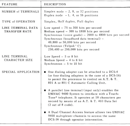
2.5.4.2. Line Terminal
FEATURE
NUMBER of TERMINALS
TYPE of OPERATION
LINE TERMINAL DATA TRANSFER RATE
LINE TERMINAL CHARACTER SIZE
SPECIAL APPLICA TION
DESCRIPTION
Simplex mode - 2, 8, or 32 positions Duplex mode - 1, 4, or 16 positions
Simplex, Half duplex, Full duplex
Low speed - 75 to 300 bits per second Medium speed - 300 to 1800 bits per second
Synchronous (voice grade) - 2000 to 4800 bits per second Synchronous (broadband data terminal)
-40,800 or 50,000 bits per second Sync hronous (Te lpa k t C)
230,400 or 250,000 bits per second
Low Speed - 5 or 8 bit Medium Speed - 4 to 8 bit Synchronous - 5 to 10 bit
• One dialing adapter can be attached to a DCS-4 (or four dialing adapters in the case of a DCS-16) to permit the process or to control an A. T. & T. 801 A or 801 C Automatic Calling Unit.
• A parallel line terminal (input only) enables the UNIVAC 9400 System to interface with a Touch-Tone* telephone. It operates at 10 characters per second by means of an A. T. & T. 403 Data Set (2 out of 8 code).
• A Dual Channel Access feature allows two UNIVAC 9400 multiplexer channels to access the same DCS-16 through operator intervention.
Table 2-2. Line Terminal Characteristics
*Registered Service Mark of A.T. & T. Co,
2.5.4.3. Communication Interface Unit
2.5.4.4. Asynchronous Timing Assembly
The asynchronous timing assembly provides a clock source for asynchronous line terminals. A single unit provides one baud rate for an entire Data Communication Subsystem. Asynchronous timing assemblies are available in baud rates up to
1800 baud. Each different speed asynchronous line terminal requires an asynchronous timing assembly. The maximum number of ATA's are four and six in the case of the DCS-4 and DCS-16.
2.5.4.5. Sync hronous Timing Assem bly
The synchronous timing a ssem bly provides a clock source for synchronous
comm unica tion. C lock signals are supplied for transmission, and provide the baud rates of 1200 to 40,800. These assemblies are needed only in a synchronous mode of operation where an asynchronous modem is used or where there is no external sync hronized clock.
2.5.4.6. Configurations
The Data Communication Subsystem configurations have been classified into the follow ing three types:
• DCS-l provides either two simplex or one duplex position. • DCS-4 provides either eight simplex or four duplex positions.
• DCS-16 provides either 32 simplex or 16 duplex positions.
The configuration shown in Figure 2-3 shows a UNIVAC Data Communication Subsystem connected to some of the more commonly used remote devices. It should be noted tha t each remote device requires a specific com bina tion of the follow ing uni ts:
• Line Terminal Controller
• Line Terminals
• Timing Assem blies - Asynchronous Timing Assemblies and/or Synchronous Timing Ass em blies
• Automatic Dialing Adapter
• Communication Interface Unit
I I I I I
L _ _
NO MODEMS NEEDED FOR TELEGRAPH LINES r--I I I I I L __ LT LOW IN ---, I I I I I _+_--.J LT LOW OUT LT MED IN
ATA ATA
CI CI
UNIVAC 9400 CENTRAL PROCESSOR
LT MED OUT
MULTIPLEXER CHANNEL
COMMUNICATIONS ADAPTER
LINE TERMINAL CONTROLLER
LT SYNCH IN LT SYNCH OUT LT PARALLEL
STA ATA
CI CI
L T L T
ALL ALL L T TY PES TY PES
LEGEND
ATA-ASYNCHRONOUS TIMING ASSEMBLY
CI -COMMUNICATION INTERFACE DA -DIALER ADAPTER L T -LINE TERMINAL PAR -PARALLEL STA -SYNCHRONOUS TIMING
ASSEMBLY
U~IV,AC Innl1 c; TOUCH-TONI" . ,A,NY DEV!CE USING
33ASR 35ASR 37ASR TELEDATAc IBMr 1050 32ASR- W.U. COLLECTDATAt TELEX TWX 28ASR 33ASR 35ASR 37ASR IBM 1050 32ASR - W.U.
:DTL 1 AND 31 OCT - 2000 CRT - VARIOUS UNIVAC 9-10J PROCESSOR UNIVAC 9300 PROCESSOR UNIVAC 9200 PROCESSOR UN ISCOPE 300 OTHER UNIVAC
PROCESSORS
DIALING SWITCHFO NFTWORK FAr'11 ITIF~ [)FPFN[)INr: ON L T CHOICE
* A SECOND UNIVAC 9400 CENTRAL PROCESSOR CAN BE CONNECTED TO THE DATA COMMUNICATION SUBSYSTEM (DCS-161 THROUGH THE USE OF THE DUAL CHANNEL ADAPTER. THIS CONNECTION IS MANUALLY SWITCHED AND ALLOWS ONLY ONE PROCESSOR AT A TIME TO INTERFACE WITH THE DATA COMMUNICATION SUBSYSTEM.
- TELEX - TRADEMARK OF WESTERN UNION TELEGRAPH CO. TELEDATA AND COLLECTDATA - TRADEMARKS OF FRIDEN, INC.
IBM - REGISTERED TRADEMARK OF INTERNATIONAL BUSINESS MACHINES CORP. DATASPEED - TRADEMARK AND SERVICE MARK OF A.T. & T. CO.
TOUCH-TONE - REGISTERED SERVICE MARK OF A.T. & T. CO.
2.5.5. UNIVAC 1004 or 1005 Subsystem
The UNIVAC 1004 or 1005 Subsystem is a powerful processing unit in its own right, with arithmetic, logical, and editing capabilities allied to a modular 961-character core storage. Standard peripheral units are a 400 cpm or 615 cpm card reader, a high speed printer operating at 400 lpm or 600 lpm with a 63 character set and 132 character print line width. A card punch operating at 200 cards per minute may also be included. External interrupt, punch stacker select, and alternate print code features are required when the UNIVAC 1004 or 1005 is used as a subsystem to the UNIVAC 9400 System.
Optional units for the offline configuration are a second bank of 961 characters of
core storage, a second card reader (400 cpm), a card punch or card read/punch
(200 cpm), UNIVAC 1001 Card Controller, paper tape reader (400 cps), a paper tape
punch (110 cps), and one or two UNISERVO VI C Magnetic Tape Units.
A UNIVAC 1004 or 1005 Subsystem can be connected online, by means of one of the eight subchannels of the basic multiplexer channel, to the UNIVAC 9400 System To provide card reading, card punching, and printing capability.
A special plugboard is required when the UNIVAC 1004 or 1005 Subsystem is to be used online with the UNIVAC 9400 System. The 1004 or 1005 Subsystem retains its freestanding processing power when used in this configuration. At any time, the 1004 or 1005 Su bsy stem can be swi tched to offline mode, and it then operates as a standard freestanding model.
By attaching one of several types of line terminals, this subsystem can function as a remote data processor connected through a communications line to the UNIVAC 9400 System. Transmission at speeds of 2000, 2400 or 40,800 bauds is possible depending upon the types of line terminals and communications facility employed.
UNIVAC 1004 OR 1005 SUBSYSTEM CHARACTERISTICS
ONLINE AND OFFLINE
CARD READING SPEED 400 or 615 cpm
CARD PUNCHING SPEED 200 cpm
PRINTING SPEED 400 or 600 Ipm
PRINTABLE CHARACTERS PER LINE 63 plus space
NUMBER OF CHARACTERS PER LINE 132
NUMBER OF LINES PER INCH 6 or 8
MAIN STORAGE 961 character positions
NUMBER OF INPUT/OUTPUT CHANNELS USED 1
OFFLINE ONLY
CARD READING SPEED 400 cpm auxiliary reader
1000 or 2000 cpm with UNIVAC 1001 Card Controller
MAIN STORAGE 1922 cha racter pos itions
MAGNETIC TAPE One 0 r tw 0 U N IS E R V 0 V I C Tap e Units
MAGNETIC TAPE CODE CONVERSION Available in UNIVAC 1004 Subsystem using the automatic translate feature
TAPE TRANSFER RATE 8,500; 23,700; and 34,200 characters
per second
RECORDING DENSITY 200, 556 or 800 ppi
PAPER TAPE READ 400 characters per second
PAPER TAPE PUNCH 110 characters per second
REQUIRED FEATURES
2.5.6. UNIVAC 9200 or 9300 Subsystem