Modification, practical application and
numerical study of air-cathode
microbial fuel cells
By
Dunzhu Li
A thesis submitted for the degree of Doctor of Philosophy to the University of Dublin, Trinity College.
Department of Civil, Structural and Environmental Engineering
Trinity College
University of Dublin
i
Declaration
I declare that this thesis has not been submitted as an exercise for a degree at this or any other university and it is entirely my own work.
I agree to deposit this thesis in the University’s open access institutional repository or allow the library to do so on my behalf, subject to Irish Copyright Legislation and Trinity College Library conditions of use and acknowledgement.
________________________
ii
Abstract
Microbial fuel cell (MFC) technology has been attracting great attention recently due to its potential for simultaneously harvesting electric energy, removing pollutants and monitoring organic matter concentration at wastewater. To date, the air cathode has been the bottleneck for MFC development. To deepen the understanding and improve the performance of air-cathode MFC, the study was conducted through 3 aspects of air cathode: surface and structural modification, practical application and numerical modelling.
In a surface modification study, it was found that sufficient catalyst (38 mg/cm2) was critical to
generate high power density and coulombic efficiency (CE) and maintain good performance at long-term operation. As to blended material, Ti-blended reactors obtained slightly higher performance than carbon black (CB)-blended MFCs in terms of power density, CE and long-term stability. Over short-term operation (1 month), Cu-blended reactors showed the worst performance due to copper ion inhibition over anode biofilm. However, Cu-blended reactors achieved the best performance over long-term operation (4.5 months). High pressure and temperature (HPT) treated by autoclave was a convenient and efficient method to modify cathode. With this method, the power density increased regardless of the blended material. HPT modification could also remove the short-term inhibition of Cu and generate much higher maximum power density over CB and Ti. In terms of the separator, Denim fabric (DF) had a similar short-term performance to that of glass fibre (GF). After the 5-months of operation, DF achieved much higher CE than GF due to its stability and anti-microbial growth.
In terms of structural modification, a novel 3D cathode which could significantly increase MFC’s cathode specific surface area (CSSA) was developed and tested. The maximum power density was improved from 23 ± 2 W/m3 to 46 ± 1 W/m3 when the flat cathode – a common cathode
widely used in MFCs - was changed to the 3D cathode. The significant improvement (increased by 248%) was also obtained when further increased the CSSA to 219 m2/m3. The 3D cathode also
increased CE by 28% due to the advantages of full organic matter consumption and cathode biofilm inhibition. COD removal rate showed good agreement with first-order degradation kinetic regardless of the CSSA difference. Over long-term operation, the MFC with the low CSSA (41 m2/m3) demonstrated a very high stability while the power of MFCs with high CSSA (104-509
m2/m3) showed a reversible change, which was due to the mass oxygen crossover.
Then the 3D cathode was employed to construct the configuration of cathode surrounding anode (CSA) with large volume. In practical application of dairy wastewater, CSA with 3D cathodes obtained high power generation (4.7 ± 0.2 W/m3) and 88.0%- COD and 93.9%-TN removal,
respectively. In addition, the 3D cathode could reduce the NH3 emission significantly. It was also
iii
3D cathode blended with Cu particles could further improve the power generation performance, reduce the NH3 emission and enhance the total nitrogen (TN) removal.
In addition to treating real wastewater, MFC was also developed as a sensor to selectively test urine glucose. The novel structure of self-cleaning sensor (SCS), obtained quick response (6.7 ± 0.4 minutes), large detection range (0.3-2 mM) and excellent linear relationship (R2 higher than
0.98) between glucose concentration and peak currents. More importantly, SCS obtained up to the 5 months of stable operation, around 100% longer than traditional flat MFCs. In addition to peak current, the current increase rate was an alternative parameter to indicate the glucose concentration with quicker response (100 s) and larger detection range (0.3-5 mM). The selectivity of SCS was validated by using both synthetic and real diabetes-negative urine samples. In terms of accuracy, SCS showed a good agreement compared to a commercial glucose analyser (recovery ranged from 93.6 % to 127.9 %) when the diabetes-positive urine samples were tested. Due to the multiple advantages (high stability, low cost and high sensitivity and selectivity) over urine test strip, SCS provides a novel and reliable approach for continuous monitoring of urine glucose, which will greatly benefit diabetes assessment and control.
Finally, a robust 3D model was developed to investigate the potential optimum configuration. The numerical results showed that most of the areas of cylindrical cathodes are active during the reaction, which reveals the reason for the high efficiency of the CSA configuration. In terms of cathode area, the study showed that 90 m2/m3-CSSA was the optimum value to maximize current
iv
Acknowledgements
First and foremost, I would like to thank my supervisor, Dr. Liwen Xiao for the opportunity to let me be a part of the Department of Civil, Structural and Environmental Engineering and Trinity Haus at Trinity College Dublin. Throughout my PhD period, his patience, guidance and supports play key role in the findings presented here. I feel very lucky to have a supervisor who I really enjoy working with. In addition to my project, he also gave me piles of supports in my daily life. Because of his warm and persuasive reference, I successfully rented an apartment in the city centre in August 2018. All Dubliners know how competitive of rent market at that time!!
As a member of Department of Civil, Structural and Environmental Engineering, I am grateful that we have a group of professional and reliable staff. Thanks to Kevin, David Mc Aulay and Gerald, they gave me lots of professional suggestions and help. Thanks to Professor Laurence Gill, his passion on both work and life significantly inspired me.
I would like to give a special thank to Mr Patrick Veale, who always tried his best – sometimes even sacrificed his weekend – to complete my request. I would also like to thank the School of Engineering and CSC for their financial support for my study. I am grateful to Dr Lei Xu and Ranbing Liu of UCD, their suggestions were critical for the start of my study.
I feel so lucky to have the nice colleague, Dr. Richard O’Hegarty, at our office. In addition to introducing Irish culture and playing football, he also gave me lots of professional and patient supports when I developed COMSOL model. I am grateful that I have a warm, sincere and helpful teammate, Fei, who gave me lots of help in both work and life. I also feel lucky to be a part of Trinity Haus. I would like to thank to Dimitra for her organization and all others (Oliver, Chris, Ahmed) for sharing their stories during our weekly Friday coffee mornings.
v
Table of Contents
Declaration ... i
Abstract ... ii
Acknowledgements ... iv
Table of Contents ... v
List of Figures ... viii
List of Tables ... xii
List of Acronyms ... xiii
1 Introduction ... 2
1.1 Background ... 2
1.2 Research objectives ... 4
1.3 Thesis outline ... 5
2 Literature Review ... 7
2.1 Air cathode structure development ... 7
2.1.1 Original two-layer structure ... 10
2.1.2 One-layer structure ... 13
2.1.3 Four-layer structure ... 13
2.1.4 Three-layer structure ... 15
2.1.5 Mixed two-layer structure ... 17
2.1.6 Separator support (SES) structure ... 19
2.2 Practical application of air-cathode MFCs ... 21
2.2.1 Real wastewater treatment ... 21
2.2.2 Air-cathode MFCs based sensor development ... 26
2.3 Modelling the development of air-cathode MFCs ... 29
2.4 The bottlenecks of MFCs study and application ... 33
3 Materials and Methods ... 37
3.1 Introduction to the experimental system ... 37
3.2 MFC construction and operation ... 38
3.3 The collection, storage and test of wastewater & urine samples ... 40
vi
3.5 Measurement and analysis ... 42
3.6 The MFC based Model development ... 44
4 Understanding the startup process and current plummeting of MFCs ... 47
4.1 Startup process of MFCs ... 48
4.1.1 Inoculum influence on MFCs startup ... 48
4.1.2 Power performance after startup ... 50
4.2 Current Plummeting phenomenon ... 52
4.2.1 External resistance influence on CPP ... 54
4.2.2 Chamber structure influence on CPP ... 55
4.2.3 Anode influence on CPP ... 57
4.2.4 Cathode influence on CPP ... 58
4.2.5 The empirical equation for CPP ... 60
4.2.6 The triggering process of current plummeting ... 62
4.3 Conclusions for Chapter 4 ... 63
5 Surface modification of air cathode ... 66
5.1 Catalyst loading influence on MFCs performance ... 66
5.1.1 Catalyst loading influence on power generation ... 66
5.1.2 Catalyst loading influence on CE and long-term performance ... 67
5.2 Blended material influence on MFCs performance ... 69
5.2.1 Blended material influence on power generation... 70
5.2.2 Blended material influence on CE ... 72
5.2.3 Blended material influence on the long-term operation ... 73
5.3 Separator influence on MFCs performance ... 74
5.3.1 Separator influence on power generation ... 75
5.3.2 Separator influence on CE and long-term performance ... 77
5.3.3 Separator property analysis ... 79
5.4 Conclusions for Chapter 5 ... 82
6 Structural modification of the air cathode ... 84
6.1 Power production ... 85
vii
6.3 COD removal and power output ... 89
6.4 Long-term operation and power restoration ... 91
6.5 Conclusions for Chapter 6 ... 93
7 Practical application of modified MFCs ... 95
7.1 MFCs operation with dairy WW ... 95
7.1.1 Enlarged MFCs performance with CSA and CIA ... 96
7.1.2 Ammonia emission ... 100
7.1.3 Pathway of ammonium removal ... 103
7.1.4 Control of ammonia emission ... 105
7.2 Diabetes’ detection sensor development based on air-cathode MFCs ... 107
7.2.1 Configuration influence on sensor performance ... 109
7.2.2 Selectivity of SCS ... 112
7.2.3 Improvement of SCS performance... 114
7.2.4 Practical application and cost analysis ... 115
7.2.5 Commercial potential of the sensor... 118
7.3 Conclusions for Chapter 7 ... 119
8 Numerical study of air-cathode MFCs ... 121
8.1 3D model development ... 121
8.2 3D model validation ... 124
8.3 Modelling results of CSA structure ... 125
8.4 Modelling results for the optimal structure... 126
8.5 Conclusions for Chapter 8 and the outlook of MFC based WWTP ... 128
9 Conclusion and Recommendation ... 131
9.1 Conclusion ... 131
9.2 Contributions to knowledge. ... 133
9.3 Future research ... 134
viii
List of Figures
Figure 1.1 Schematic of typical air-cathode MFC. ... 2
Figure 1.2 General overview of the thesis. ... 5
Figure 2.1 Critical development of air cathode. ... 9
Figure 2.2 Typical making procedures of different cathode structures. ... 10
Figure 2.3 Practical application with different volumes. ... 22
Figure 2.4 PCA biplot for all cases of MFCs’ practical application. ... 25
Figure 2.5 Cost analysis of MFCs employed with different cathodes ... 26
Figure 2.6 Typical bio-sensor made by air-cathode MFC ... 29
Figure 2.7 Typical simulation results from different models ... 31
Figure 2.8 Typical simulation results from COMSOL ... 32
Figure 2.9 The working window of COMSOL ... 33
Figure 2.10 Research contents of this study ... 35
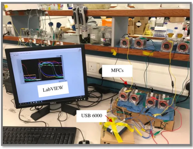
Figure 3.1 MFCs study system ... 37
Figure 3.2 LabVIEW interface of data acquisition window (left) and block diagram (right) .... 38
Figure 3.3 MFCs used at study (left) and block diagram (right)... 38
Figure 3.4 Flat cathode (Left) and cylindrical cathode (Right)... 39
Figure 3.5 Schematic diagrams of NH3 collection air chamber for 1Flat (up) and CSA (down). ... 41
Figure 3.6 NH3 collection air chambers: 1Flat (up) and CSA (down). ... 42
Figure 3.7 Potentiostat for LSV test (left) and mini-sensor for DO monitoring (right) ... 44
Figure 4.1 typical current plummeting at the operation of MFCs ... 47
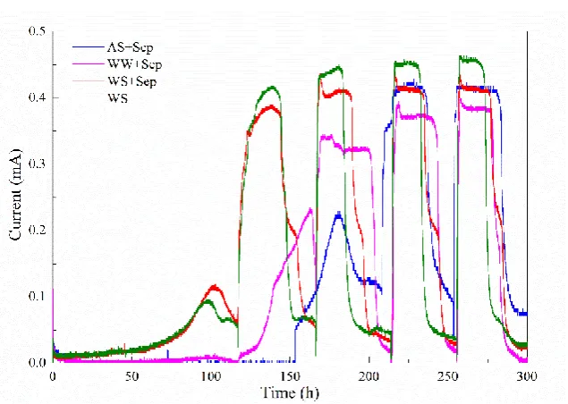
Figure 4.2 The startup of MFCs with different inoculum. ... 49
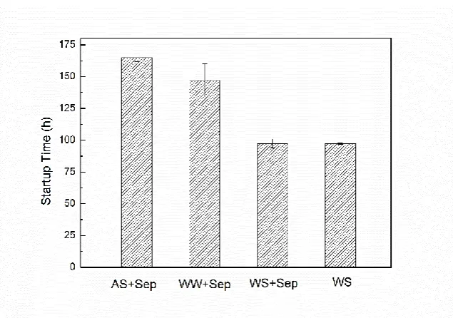
Figure 4.3 Startup time of MFCs with different conditions ... 50
Figure 4.4 MFCs’ power density curves after 16-day (5 cycles) operation. ... 51
Figure 4.5 Curves of MFCs’ power density (A) and electrodes potential (B) after 1.5-months operation (solid symbols, anode potentials; open symbols, cathode potentials). ... 52
Figure 4.6 Pictures of different types of MFCs used in this section ... 53
Figure 4.7 sCODCPP concentration change with different currents (R1 in Table 4.1)... 55
Figure 4.8 (A) sCODCPP concentration change with different volumes (R1-5 in Table 4.1); (B) sCODCPP distribution at different locations of MFCs chambers (R3-5 in Table 4.1). ... 56
Figure 4.9 sCODcpp distribution with different GFB loadings and location. ... 58
ix
Figure 4.11 (A) Empirical equation fitting result; (B) Prediction and validation of empirical equation (Legend: L-PL: Lower prediction limit of 95%; U-PL: Upper prediction limit of 95%).
... 61
Figure 4.12 (A) Current plummeting at the operation of MFCs (CPP: current plummeting point; external resistance was 100 Ω); (B) The triggering process of current plummeting. ... 63
Figure 5.1 Curves of MFCs’ power density (A) and electrodes potential (B) with different catalyst loading (solid symbols, anode potentials; open symbols, cathode potentials). ... 67
Figure 5.2 CE of MFCs with different catalyst loading. ... 68
Figure 5.3 Long-term power density curves of MFCs with different catalyst loading. ... 69
Figure 5.4 The blended materials (left to right: CB, Cu, Ti). ... 69
Figure 5.5 Curves of MFCs’ power density (A) and electrodes potential (B) with different catalyst loading (solid symbols, anode potentials; open symbols, cathode potentials). ... 71
Figure 5.6 CEs of MFCs with the change of blended material and HPT treatment. ... 73
Figure 5.7 Power density curves of (A) 1.5 months and (B) 4.5 months. ... 74
Figure 5.8 (A) Power density curve and (B) electrodes potential obtained from the fast test. ... 76
Figure 5.9 MFCs’ curves of power density (A) and electrodes potential (B) with different test method (solid symbols, anode potentials; open symbols, cathode potentials). ... 77
Figure 5.10 CEs of MFCs at (A)1.5 months and (B) 5 months. ... 78
Figure 5.11 Power density curves with different operation time. ... 79
Figure 5.12 SEM results of (A) GF and (B) DF. ... 80
Figure 5.13 Separator of glass fibre before (A) and after (C) long-term operation (5 months); denim fabric before (B) and after (D) long-term operation and J-cloth after long term operation (E, F, less than 3 months). ... 81
Figure 6.1 Configurations of interlocked MFCs (left to right: 1Cyl, 2Cyl; 3Cyl; 4Cyl). ... 85
Figure 6.2 MFCs tests: (A) power density curves; (B) power curves; (C) electrode potentials (solid symbols, anode potentials; open symbols, cathode potentials). ... 87
Figure 6.3 Internal resistance, CE and maximum power for different MFCs. ... 89
Figure 6.4 COD removal rate fitting with first-order reaction for different MFCs. ... 90
Figure 6.5 Power and COD change with time for 1Flat, 1Cyl, 2Cyl (A) and 3Cyl, 4Cyl. ... 91
Figure 6.6 Power change under long-term operation for different MFCs (Power restoration was conducted at cycle 53-60, between two arrows). ... 93
Figure 7.1 Details of enlarged MFCs. Both CSA and CIA reactors have a cubic chamber of 60mm×80mm×80mm, the net volumes were 250 mL. The surface of all cylindrical cathodes were covered by separated material of denim fabric. ... 96
Figure 7.2 The performance of CSA and CIA with different cathode number: (A) power density curves; (B) COD removal and (C) TN removal. ... 98
x
Figure 7.4 N-pollutants removal and emission with and without biofilm: (A) NH3 emission and
NH4+ removal; (B) TN, NO2- and NO3- removal inside of MFCs (1Flat-MFCs). ... 101
Figure 7.5 (A) Current and influent concentration influence on NH3 emission (1Flat;
50N&1000Ω:NH3-N in influent 50 mg/L and external resistance 1000 Ω; other legends similar);
(B) NH3 emission of CSA with different cathode numbers (1C – 1 cathode; 2C – 2 cathodes).
... 102 Figure 7.6 Potential emission process of NH3/NH4+ in the surface of air cathode... 103
Figure 7.7 (A) N-pollutants removal and NH3 emission process with and without NOB selective
inhibitor (1Flat-MFCs, feeding with sodium acetate); (B) The biological nitrogen conversions (Kampschreur et al. 2009). ... 105 Figure 7.8 Performance of Cu-blended CSA: (A)power density curves and COD/TN removal process; (B) NH3 emission with different cathode numbers (1C-1 cathode: CSSA of 12.3 m2/m3;
2C-2 cathodes: CSSA of 24.6 m2/m3; 4C-4 cathodes: CSSA of 45.2 m2/m3). ... 106
xi
Figure 7.16 Current of SCS in the presence of normal urine with different dilution factors and 1mM glucose. (The urine was collected from 4 different healthy individuals and mixed for the test. The glucose concentration of this mixed urine was less than 0.2 mM, tested by commercial analyser) ... 116 Figure 8.1 Geometry of MFCs in COMOSOL. ... 121 Figure 8.2 Experimental and simulation results of: (A) Polarization curve; (B) DO change with current. ... 125 Figure 8.3 Anode surface DO distribution with the increase cathode surface (A, CSSA= 70 m2/m3;
B, CSSA= 90 m2/m3 ; C, CSSA= 110 m2/m3 ; D, CSSA= 140 m2/m3 ; total current was 20 mA).
xii
List of Tables
Table 2.1 Summary of different air cathode structures. ... 12
Table 2.2 Summary of practical applications of MFCs ... 23
Table 2.3 Summary of BOD sensor made by single chamber air-cathode MFC. ... 26
Table 2.4 Summary of models used in air-cathode MFCs. ... 30
Table 4.1 Details of MFCs used in this study. ... 53
Table 5.1 Thermal and electrical property of different materials. ... 72
Table 6.1 Details of different MFCs. ... 84
Table 7.1 - Details of enlarged MFCs ... 95
Table 7.2 - Summary of power performance obtained from different MFCs fed with dairy wastewater... 97
Table 7.3 - Summary of NH3 emission studies ... 107
Table 7.4 Determination of glucose and ethanol in real samples. ... 117
Table 7.5 Material and cost analysis ... 118
Table 8.1 Parameters used at simulation. ... 124
xiii
List of Acronyms
AC activated carbon
AEM anion exchange membrane
ALU alumina
AMPD areal maximum power density
AS activated sludge
BW brewery wastewater
C carbon
CA cathode area
CAC canvas cloth
CB carbon black
CC carbon cloth
CE coulombic efficiency
CFD computational fluid dynamics
CIA cylindrical cathode interlocked by anode
CM carbon mesh
CNT carbon nanotubes
CNTM carbon nanotube mat
COP conductive paint
CoTMPP co-tetra-methyl phenylporphyrin
CP carbon powder
CPP current plummeting point
CSA cylindrical cathode surrounded anode
xiv
CUC current collector
CV carbon veil
DF denim fabric
DL diffusion layer
DO dissolved oxygen
DSC double-side cloth
EAR earthenware
EC electrical conductivity
FA free ammonia
FEP fluorinated ethylene propylene
GF glass fiber
GFB graphite fiber brush
GFE graphite felt
GG graphite granules
GP graphite paint
HPT high temperature and pressure
IEM ion exchange membrane
LED light-emitting diode
LEV levofloxacin
LSV linear sweep voltammetry
MFC Microbial Fuel Cell
MMM M9 minimal medium
MOC monolith carbon
xv
MPD maximum power density
MUL mullite
NOB nitrite-oxidizing bacteria
OCP open circuit potential
PBS phosphate-buffered saline
PCA Principal component analysis
PDMS poly dimethylsiloxane
PEM proton exchange membrane
PIM phase invention method
PL prediction limit
PS plastic sieves
PTFE polytetrafluoroethylene
PUR polyurethane
PVC polyvinyl chloride plastic
PVDF Polyvinylidene fluorine
PYR pyrophyllite
RPE relative prediction error
RSD relative standard deviations
SAL separated layer
SCD secondary current distribution
SEA separator electrode assembly
SES separator support
SM separated material
xvi
SOA sodium acetate
SPA closely spaced electrodes
SPEEK sulfonated poly ether ether ketone
SSM stainless steel mesh
SUL support layer
TC terracotta
TDS transport of diluted species
TEC thermal expansion coefficient
TN total nitrogen
UM ultrafiltration membrane
V volume
VMPD volumetric maximum power density
WS activated sludge from wastewater treatment plant
WW Wastewater
1
Chapter 1
2
1
Introduction
1.1
Background
Microbial fuel cell (MFC) technology has been attracting great attention recently due to its potential for simultaneously harvesting electric energy and removing pollutants from wastewater. Fuelled with wastewater (WW), the anode biofilm degrades organic matter and generates electrons and protons (Figure 1.1). The electrons flow from anode through an external resistor to the cathode while the excessive protons diffuse to the same location. Reacting with final electron acceptor-O2, both water and current are generated when this reaction is completed (Logan et al.
[image:22.595.116.449.269.626.2]2006).
Figure 1.1 Schematic of typical air-cathode MFC.
Picture sources: (Ou et al. 2016b, Wang et al. 2017b)
3
The anode provides surface area to support the growth of electrogenic bacteria. These special bacteria could degrade organic matter, obtain and transfer electrons to the anode. The anode then collects these electrons and transfers them to the external circuit. Therefore, the anode must be biocompatible, electric conductive and chemical stable. To date, the most versatile anode material is carbon, such as carbon cloth and graphite fiber brush (GFB).
The cathode is where the final step of Redox reaction (Equation 1.2) completes. The air cathode uses oxygen from the air as the final electron acceptor, which has many advantages, such as high oxidation potential, low cost and sustainability. However, it has slow reduction reaction kinetics when the plain carbon is used cathode materials. To accelerate the reduction reaction rate, different types of materials such as Pt and activated carbon have been added as catalysts to the cathode. In fact, catalyst places a critical role for the cathode reaction (Equation 1.2). Catalyst is a substance which increases the chemical reaction rate while there is no consumed of this substance in whole process. Summarising previous reports, in addition to the precious metals, there were 3 substances showing the function of catalysis: activated carbon (AC), carbon black (CB) and cathode biofilm. AC is an excellent catalyst at cathode. Changing carbon cloth to AC, the maximum power density could be increased from around 50 mW/m2 to 1630 mW/m2 (Liu et
al. 2014, Zhang et al. 2009a). CB could benefit the current generation. With the blending of CB, the current was achieved 21% improvement (Zhang et al. 2014b). The cathode biofilm which grows on the surface of cathode facing solution could promote the maximum power generation by around 10% (Ou et al. 2016a). It this study, the cathode catalyst only denotes as AC.
Cathode requires oxygen. To benefit the oxygen diffusion inside of cathode, the diffusion layer is employed on the cathode surface that facing the air. Some oxygen may diffuse through cathode to reach anode. However, the anode and the whole chamber should keep low dissolved oxygen concentration (such as around 0.3 mg/L) to favour the activity of anode biofilm. This oxygen crossover inhibits anode biofilm and reduces the power generation of MFC. To prevent the oxygen crossover, separator such as glass fiber paper is needed to place next to the cathode surface that facing the solution.
In terms of the external circuit, it generally consists of metal wire and resistance. Connecting anode and cathode with external circuit, the electrons generated at anode could easily flow to cathode. With the flow of electron, the current is generated.
Taking sodium acetate as an example, the anode reaction can be written as
CH3COO- + 4H2O →2HCO3- + 9H+ + 8e- (1.1)
4
O2+ 4H+ + 4e- → 2H2O (1.2) (1.2)
The overall reaction can be written as
CH3COOH + 2O2 → 2CO2 + 2H2O (1.3)
The methodology of MFCs is similar to chemical cells, such as hydrogen cells. In 2004, the first single chamber air-cathode MFC was invented (Figure 1.1). Different from the previous types of MFC, this new configuration has only 1 chamber and the cathode directly faces air where it can use oxygen as an electron acceptor. Due to the low operational cost, simple configuration and high power generation, the single chamber air-cathode MFCs illustrate great advantages for practical applications. Since the first air-cathode single chamber MFC was reported in 2004, this paper has been recited over 1700 times (Google scholar, 30.04.19), which indicates the importance and popularity of this configuration. The air cathode is the core part of the air-cathode MFCs because it is responsible for oxygen diffusion/reduction and power generation. Compared with the anode, the cathode contributes 8 times more in terms of the internal resistance. With the multifunction, the cathode determines the performance and cost of the MFC system. To date, the air cathode has been the bottleneck for MFC development, especially for practical application. Therefore, it is very important to deepen the understanding of and improve the performance of the air cathode.
1.2
Research objectives
The main aim of this study is to modify the air cathode structure to improve the performance of MFCs. Specifically, the objectives of this research are:
➢ To have a deep understanding of MFC’s startup process and current plummeting phenomenon, which can accelerate MFCs operation, maximize current recovery and promote effluent quality;
➢ To determine the influence of cathode catalyst loading, blended materials and separator on MFCs’ performance;
➢ To develop a novel 3D cathode to break through the limit of cathode specific surface area;
➢ To develop enlarged MFCs and evaluate their performance on the treatment of real dairy WW;
5
➢ To establish a robust 3D model to understand the current generation and oxygen diffusion process inside of MFCs;
➢ To develop the optimum MFCs configuration for maximizing power generation and pollutants removal.
1.3
Thesis outline
Figure 1.2 showed a general overview of this research. This thesis is structured into seven subsequent chapters (Chapter 2 to Chapter 9). A comprehensive literature review was conducted in Chapter 2 while the relevant study parameters and methods were introduced in Chapter 3. Chapters 4-8 were the primary research sections of this thesis. Chapter 4 focused on the study of MFCs’ current startup and plummeting process while Chapters 5 and 6 explored the feasible methods for cathode surface and structure modification. Based on the results obtained in Chapters 4-6, applications of MFC for wastewater treatment and urine glucose monitoring were investigated in Chapter 7. Finally, to obtain the optimum configuration of MFCs and visualize the inside reaction, a robust 3D model was developed in Chapter 8. The key conclusions and recommendations obtained in this study were presented in Chapter 9.
6
Chapter 2
7
2
Literature Review
This chapter is divided into four primary sections. The structure evolution of air cathode in the past decade was comprehensively presented in Section 2.1. Practical application of MFC for WW treatment and pollutants monitoring was reviewed in Section 2.2. In addition, the numerical studies of air-cathode MFCs were summarized and compared in Section 2.3. Finally, the challenges of MFCs development and application was discussed in the final section (Section 2.4).
2.1
Air cathode structure development
MFC technology has been attracting great attention recently due to its multi-advantages, such as low operational cost, simple configuration and high-power generation. Since the invention of air-cathode MFC, many efforts have been made to increase the electrodes surface area, improve the performance and reduce the cost. Cheap materials such as graphite plates or rods can be used as anode, but the current performance is relatively low. To improve the performance, different physical and chemical modifications have been employed: coding Mn and Fe on the anode surface improved electrons transfer; painting composites of polyanilins/Pt could benefit the direct oxidation of anode bacteria and increase power generation; heat treatment (around 450 ℃, around 30 mins) and ammonia coating at the anode was also a feasible method to improve reactor’s performance (Fan et al. 2007, Logan et al. 2006, Lowy et al. 2006, Zhang 2012). However, the breakthrough of anode didn’t occur until 2007, when graphite fiber brush (GFB) was firstly invented and employed to MFCs(Logan et al. 2007). This invention increases the surface area of anode by 3 orders of magnitude and could provide sufficient surface area for biofilm growth (Feng et al. 2010, kumar et al. 2013). With simple heat pre-treatment, GFB could significantly increase MFCs’ power density (2400 mW/m2, normalized to cathode surface area). Since then,
GFB has become the most used anode at MFC study.
8
and very good power performance was achieved (Zhang et al. 2010a). Since then, AC and SSM have become the most common materials used for the air cathode (Yang et al. 2014a). In 2011, a single layer of CNT mat (CNTM) was directly used as the air-cathode and obtained relatively high power density (Wang et al. 2011a). This 1-layer cathode structure was successfully employed in the treatment of brewery WW(Lu et al. 2017). In 2012, the ceramic-based cathodes were successfully tested, which significantly reduced the MFCs cost (Ajayi and Weigele 2012). In 2013, a biocathode was employed as the air cathode directly and high power was obtained. However, this power decreased in long-term operation because of the growth of heterotrophic bacteria at the cathode (Xia et al. 2013). In 2014, a simple one-step, phase inversion process was invented to make air cathode. With this invention, the cathode structure and fabrication procedure was significantly simplified while the good power performance was also obtained (Yang et al. 2014a). In 2016, a 300-litre ceramic-based MFC module was assembled. This module generated the maximum power of 400 mW and successfully lighted LED lights using human urine (Ieropoulos et al. 2016).
In terms of the assemble of electrodes, the anode and cathode were usually placed on the opposite sides of the chamber in the early stage of air-cathode MFC study. (Cheng et al. 2006b) found that decreasing the electrodes distance (from 2 cm to 1 cm) could improve the power density from 811 to 1540 mW/m2. Hence, the anode and cathode were tried to placed together. And a
sandwich-like electrodes structure was developed (the J-cloth was placed in the middle of anode and cathode) by (Fan et al. 2007). In 2012, the double sandwiched electrodes were assembled via placing 2 sandwiched electrodes at opposite sides of MFC chamber (Zhang 2012). This sandwiched structure was also wrapped around the perforated plastic tube to benefit the wastewater flow and organic matter distribution(Zhuang et al. 2009). All these structures significantly improved the power performance and benefited the future scale-up of MFC. However, when GFB is used as anode, it is very difficult to assemble anode and cathode in a simple shape. To some extent, the invention of GFB limits the cathode development. In order to sustain the intactness of GFB, the compact and high-performance configuration (such as sandwiched electrodes) cannot be employed in MFCs. New design, such as wrapping cathode around GFB, were developed to increase cathode’s surface area. However, with such design the CSSA would decrease with the increase of the chamber size. MFCs even with the tube chamber as small as 2.5 cm in radius merely has 80 m2/m3 of CSSA, not to mention the larger scale MFCs
9
Figure 2.1 Critical development of air cathode.
A: (Liu and Logan 2004); B:(Cheng et al. 2006a); C: (Fan et al. 2007); D: (Zhuang et al. 2009); E:(Zhang et al. 2009a); F:(Liu et al. 2014, Zhang et al. 2011b); G: (Wang et al. 2011a); H: (Ajayi and Weigele
2012); I: (Xia et al. 2013); J: (Yang et al. 2014a); K:(Ieropoulos et al. 2016); L: (Lu et al. 2017).
Five typical air cathode structures have been studied in the past decade: 2-layer, 1-layer, 4-layer, 3-layer and separator support (SES) structure (Figure 2.2 and Table 2.1). The performance of MFCs is affected by the cathode structure. For example, compared with the 2-layer cathode, 4-layer cathode MFC could improve coulombic efficiencies (CE) by 171% (Cheng et al. 2006a); Employing activated carbon, 2-layer and 3-layer cathodes could obtain the power density of 6.3 mW/m2 and 1220 mW/m2, respectively (Liu et al. 2014, Zhang et al. 2009a). The total cost of
MFCs is also affected by the cathode structures. The cost of the typical 4-layer cathode (made by brushing method) was 1814 $/m2 while 2-layer cathode was only 15 $/m2 (made by phase
inversion method) (Yang et al. 2014a). With ceramic SES structure, the MFC cost could be reduced from around 6000 $/m3 to less than 2000 $/m3 because the low-cost ceramic material
10
[image:30.595.112.446.134.448.2]In order to promote MFC performance and practical application, it is important to understand the development and evolution of the air cathodes and the benefits and drawbacks of different air cathode designs.
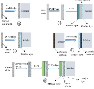
Figure 2.2 Typical making procedures of different cathode structures.
A: 1-layer cathode; B: 3-layer cathode; C: 2-layer cathode; D: separator support structure cathode; E: 4-layer cathode; e: 4-4-layer cathode.
2.1.1
Original two-layer structure
The first air cathode for the single chamber MFC was a typical two-layer structure cathode (Figure 2.1A). This cathode consisted of a carbon paper (acted as a support layer, SUL) and Pt (0.35 mg/cm2, acted as a catalyst layer, CL) (Liu and Logan 2004). The power density of this air
cathode MFC reached a maximum of 494 ± 21 mW/m2 using glucose, much greater than the
11
produced between 2 and 17 times more power per initial fabrication or purchase cost than the Pt cathodes(Morris et al. 2007). However, PbO2 is not feasible for MFC scale-up application due to
its potential biological toxicity. Three manganese dioxide materials, α-MnO2, β-MnO2, γ-MnO2
were also tested as alternative cathodic catalysts to Pt. β-MnO2 appeared to have the highest
catalytic activity due to its highest surface area (Zhang et al. 2009b). With a comparable power production, MnO2 coated cathode costs less than 5% of the previously reported membrane
cathode assembly (Zhuang et al. 2009). The transition metal oxide composite, which is cheap and stable, is also considered as an alternative catalyst to Pt (Hernández-Fernández et al. 2015). With air saturated electrolyte solution, the performance of FePc and CoTMPP was very similar to Pt oxygen electrodes (Cheng et al. 2006c, Zhao et al. 2005, Zuo et al. 2007). Increasing salinity was a feasible method to improve the performance of CoTMPP. When 250 mM NaCl was added, the power density reached up to 1062 ± 9 mW/m2, which was 25 ± 1% higher than that achieved with
Pt on carbon cloth(Wang et al. 2011c). CoNPc and PFeEDTA also demonstrated good properties when they were employed as catalysts (Kim et al. 2011a, Wang et al. 2011b). Although the metal oxide and transition metal oxide composition are competitive over Pt, they are still too expensive to be used in practice and alternative low-cost cathode catalyst materials are needed for the MFC application. In 2009, activated carbon (AC) was proved to be a cost-effective material for MFC operation for the first time(Zhang et al. 2009a). Since then, AC has been widely recognised as the most suitable catalyst for the air cathode and many studies have been carried out to find the right support materials that suit carbon catalyst as well as having low cost.
Double-side cloth (DSC) coated with conductive nickel-copper alloy was proved to be a suitable support layer and current collector for air cathode. Using Pt as a catalyst, the maximum power density (MPD) obtained from DSC was 700 ± 20 mW/m2. Using carbon powder as the catalyst
at DSC, the MPD was 410 ± 10 mW/m2, which was much lower than Pt catalyst. However, the
total cost of DSC with carbon powder was 22 $/W, only 2% of DSC with Pt, showing that DSC with carbon powder is a low-cost and promising structure for air cathode (Liu et al. 2011b). Metal mesh is another low-cost supporting material for the carbon catalyst. Employing a titanium mesh as the support and current collector, Liu et al (2011b) used four inexpensive carbon-based materials as catalysts to build packed-bed air cathodes and found that the cathodes made from AC produced the largest MPD of 676 ± 93 mw/m2, followed by semi-coke (376 ± 47 mW/ m2),
graphite (122 ± 14 mW/m2) and carbon felt (60 ± 43 mW/m2). Stainless steel mesh (SSM) was
12
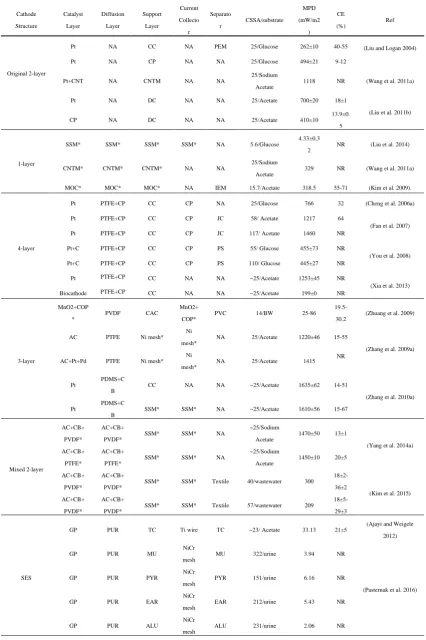
Table 2.1 Summary of different air cathode structures.
Cathode Structure Catalyst Layer Diffusion Layer Support Layer Current Collecto r Separato r CSSA/substrate MPD (mW/m2 ) CE (%) Ref Original 2-layer
Pt NA CC NA PEM 25/Glucose 262±10 40-55 (Liu and Logan 2004)
Pt NA CP NA NA 25/Glucose 494±21 9-12
Pt+CNT NA CNTM NA NA
25/Sodium Acetate
1118 NR (Wang et al. 2011a)
Pt NA DC NA NA 25/Acetate 700±20 18±1
(Liu et al. 2011b)
CP NA DC NA NA 25/Acetate 410±10
13.9±0. 5
1-layer
SSM* SSM* SSM* SSM* NA 5.6/Glucose
4.33±0.3 2
NR (Liu et al. 2014)
CNTM* CNTM* CNTM* NA NA
25/Sodium Acetate
329 NR (Wang et al. 2011a)
MOC* MOC* MOC* NA IEM 15.7/Acetate 318.5 55-71 (Kim et al. 2009).
4-layer
Pt PTFE+CP CC CP NA 25/Glucose 766 32 (Cheng et al. 2006a) Pt PTFE+CP CC CP JC 58/ Acetate 1217 64
(Fan et al. 2007) Pt PTFE+CP CC CP JC 117/ Acetate 1460 NR
Pt+C PTFE+CP CC CP PS 55/ Glucose 455±73 NR
(You et al. 2008) Pt+C PTFE+CP CC CP PS 110/ Glucose 445±27 NR
Pt PTFE+CP CC NA NA ~25/Acetate 1253±45 NR
(Xia et al. 2013) Biocathode PTFE+CP CC NA NA ~25/Acetate 199±0 NR
3-layer
MnO2+COP *
PVDF CAC
MnO2+ COP*
PVC 14/BW 25-86 19.5-30.2
(Zhuang et al. 2009)
AC PTFE Ni mesh* Ni mesh*
NA 25/Acetate 1220±46 15-55
(Zhang et al. 2009a) AC+Pt+Pd PTFE Ni mesh*
Ni mesh*
NA 25/Acetate 1415 NR
Pt
PDMS+C B
CC NA NA ~25/Acetate 1635±62 14-51
(Zhang et al. 2010a) Pt
PDMS+C B
SSM* SSM* NA ~25/Acetate 1610±56 15-67
Mixed 2-layer
AC+CB+ PVDF*
AC+CB+ PVDF*
SSM* SSM* NA
~25/Sodium Acetate
1470±50 13±1
(Yang et al. 2014a) AC+CB+
PTFE*
AC+CB+ PTFE*
SSM* SSM* NA
~25/Sodium Acetate
1450±10 20±5
AC+CB+ PVDF*
AC+CB+ PVDF*
SSM* SSM* Textile 40/wastewater 300
18±2-36±2
(Kim et al. 2015) AC+CB+
PVDF*
AC+CB+ PVDF*
SSM* SSM* Textile 57/wastewater 209
18±5-29±3
SES
GP PUR TC Ti wire TC ~23/ Acetate 33.13 21±5
(Ajayi and Weigele 2012)
GP PUR MU
NiCr mesh
MU 322/urine 3.94 NR
(Pasternak et al. 2016)
GP PUR PYR
NiCr mesh
PYR 151/urine 6.16 NR
GP PUR EAR
NiCr mesh
EAR 212/urine 5.43 NR
GP PUR ALU
NiCr mesh
13
*: a combined layer undertook at least 2 functions at cathode; CSSA: cathode specific surface area; MPD: maximum power density; CE: coulombic efficiency; NA: Not Adopted; NR: not reported; C: carbon; CC: carbon cloth; CP: carbon powder; COP: Conductive paint; CAC: canvas cloth; GG: graphite granules; PS: plastic sieves; PVC: polyvinyl chloride plastic; GFE: graphite felt; BW: brewery wastewater; CoTMPP: Co-tetra-methyl phenylporphyrin; UM: ultrafiltration membrane; GP: graphite paint; CNT: carbon nanotubes; CNTM: carbon nanotube mat; CB: carbon black; SSM: stainless steel mesh; TC: terracotta; PUR: polyurethane; CV: carbon veil; MUL: mullite; EAR: earthenware; PYR: pyrophyllite; ALU: alumina; SOA: sodium acetate; ww: wastewater; SES: separator support; IEM: ion exchange membrane; MOC: monolith carbon.
2.1.2
One-layer structure
One-layer structural cathodes have been used in MFCs successfully. These cathodes undertake the combined function of oxygen reduction and current collection. Materials such as SSM, Carbon nanotubes mat (CNTM) and monolith carbon (MOC) have been used in one-layer structural cathodes (Table 2.1). When SSM was employed at bed-packed MFC reactors, the MPDs for submerged and half submerged SSM cathodes were 1.23 ± 0.21 and 4.33±0.32 mW/m2,
respectively (Liu et al. 2014). These results (around 100-101 mW/m2) are much lower than the
values (around 102-103 mW/m2) obtained from the original 2-layer structure cathode MFCs,
which could be due to the fact that the SSM and raw carbon material (such as CB) were not effective catalysts for oxygen reduction. Carbon nanotubes (CNTs) have great potential to be used as electrode materials in MFCs because of the high surface-to-volume ratio and unique electrical and mechanical properties (Lamp et al. 2011, Xie et al. 2010, Yazdi et al. 2016). CNTM that contains more than 90% CNTs has been used as the air-cathode directly. Without any other catalyst coating, CNTM reactor showed an MPD of 329 mW/m2, more than twice of the peak
power obtained from CC reactor(Wang et al. 2011a). Multi-channel monolith carbon was also employed as a single-layer cathode (Kim et al. 2009). This material was heated at 1600 °C to improve the electrical conductivity. In order to avoid water leakage, this tubular cathode was covered by an exchange membrane. The volumetric MPD of 5 W/m3 was generated based on
reactor volume. When hydrogel was employed on the cathode surface, this value increased to 6.1 W/m3.
In conclusion, the MPD of the one-layer structure is significantly lower than that generated from the Pt-coated two-layer structure. In addition, water loss and oxygen diffusion in the anode area are also the main drawbacks for single layer construction (Cheng et al. 2006a).
2.1.3
Four-layer structure
14
mg/cm2 Pt mixed with Nafion), SUL (carbon cloth), CUC (a mixture of carbon powder and PTFE)
and DL (PTFE) (Figure 2.1B). In the MFC test, 4 times’ brushing was found to be the optimum number of DL, resulting in a 171% increase in the CE (from 19.1% to 32%) and a 42% increase in MPD (from 538 to 766 mW/m2) and significant water loss was prevented (Cheng et al. 2006a).
The order of CL and DL influenced the performance of the MFC. When CL was changed from the air facing-side of the cathode to the anode chamber solution facing side the maximum power outputs and the maximum voltage outputs increased from 0.144 mW and 0.4V to 1.16 mW, and 0.5 V, respectively (Yang et al. 2009). Similar results were also obtained in other studies, indicating that placing CL in the solution facing side of 4-layer structure cathode could increase power generation significantly (Cheng et al. 2006a, Yang et al. 2009, Zuo et al. 2008).
Due to the number of layers, the cost of a 4-layer cathode could be much higher than previous cathodes. Therefore, it is important to find low-cost alternative materials for each layer. Nafion which has been used as a binder for the catalyst is expensive. To reduce the cost, PTFE was tested as a binder. It was reported that MPD reduced from 400 ± 10 ~ 480±20 mW/m2 to 331 ± 3 ~ 360
±10 mW/m2 when the Nafion binder was replaced by PTFE (Dong et al. 2012b, Wang et al.
2010). In another study, PDMS was also tested as an alternative to Nafion (Zhang et al. 2012). With PDMS as a binder, MFCs produced MPDs of 1680 ±12 ~ 1710±1 mW/m2, which were
comparable to the Nafion binder. Furthermore, after 15 days (15 cycles) of operation, the power generation reduced by 40% for MFCs with Nafion as a blinder, while it reduced less than 20% for PDMS blinder. More importantly, the cost of PDMS is only 0.23% of Nafion (Zhang et al., 2012).
15
results show that controling the heterotrophic growth of microorganisms on cathodes is a key step for biocathode application in air-cathode MFCs.
Carbon mesh (CM) has been adopted as an alternative for CUC (Luo et al. 2011). With a study showing that both the maximum voltage outputs and MPD achieved from the MFCs with CM were similar to that for CC with 1000 Ω. However, the CEs obtained by CM were significantly higher than CC (Luo et al. 2011). Nickel foam was also employed as a support and CUC for the cathode. The nickel foam cathode MFC produced an MPD of 1355 ± 62 mW/m2, which was
comparable with 1320 mW/m2 from a typical carbon cloth Pt cathode MFC(Cheng and Wu 2013).
Furthermore, the metal mesh could also be applied to avoid cathode membrane deformation (Zhang et al. 2010b). When SSM was used to press the membrane flat against the cathode, the MFC performance could be increased from 32 ± 2 to 46 ± 4 W/m3 (volumetric power density).
Different materials have been used to make the DL. When fluorinated ethylene propylene (FEP) was brushed as DL, 4 times’ brushing was also found to be the optimum number for oxygen diffusion. The MPD obtained was 1679 ± 265 mW/m2 while the maximum CE was 80%. In
long-term operation, the voltage of FEP-coated MFCs was slightly higher compared to PTFE-coated MFCs. Polyvinylidene fluorine (PVDF) is a semi-crystalline fluoropolymer that exhibits good physical stability and chemical resistance. It has been used as a binder in the electrodes of batteries, fuel cells and capacitors (Barsykov and Khomenko 2001). Many studies have employed PVDF as DL in air cathode and obtained good performances (Huang et al. 2010, Yang et al. 2014a, Zhuang et al. 2009). Many other materials, such as poly dimethylsiloxane (PDMS) and polyurethane(PUR) also have been adopted as DLs in MFC, and relatively high performances have been obtained (Zhang et al. 2010a).
With a 4-layer cathode employed, the power density is significantly increased from around 102
(typical 1-layer and 2-layer cathodes) to around 103 mW/m2. However, fabricating such structures
is complicated and time-consuming, and most importantly, it is very expensive (1814 $/m2)
(Cheng and Wu 2013, Yang et al. 2014b).
2.1.4
Three-layer structure
In 2009, activated carbon (AC) and metal mesh were firstly employed at air cathode(Zhang et al. 2009a). Initially, AC was cold-pressed with a PTFE binder to form the cathode around a Ni mesh the current collector; A PTFE diffusion layer was then added to the air side of cathode, which formed a typical cathode with three layers - CL of AC, support and current collector of Ni mesh (at middle) and DL of PTFE. MFCs with AC cathode produced an MPD of 1220 mW/m2
16
cathodes ranged from 15% to 55% (Zhang et al. 2009a). This study proved that AC was a cost-effective material for oxygen reduction in air cathode MFCs. Because of the low cost and good performance, AC has become the most widely used CL material to date in MFC studies (Wang et al. 2017b). Similar to the four-layer cathode, different diffusion materials, such as PVDF and PDMS, were also tested as the alternative in DL and obtained a comparable power density (Huang et al. 2010, Yang et al. 2014a, Zhang et al. 2010a).
A metal/carbon mesh also plays a crucial role as support layer and current collector for the three-layer structure cathode. Suitability of using different materials to make the mesh for the cathode was investigated. Studies showed that cathodes with different mesh materials (Ni, Cu, stainless steel, carbon) produced similar results (Luo et al. 2011, Wang et al. 2017b, Zhang et al. 2012, Zhang et al. 2009a, Zhang et al. 2011a). Due to the relatively low cost, SSM has been widely used as mesh material in the three-layer structure cathodes. Mesh size has a great effect on power generation. Cathodes made from the coarsest mesh (30-mesh) achieved the highest MPD of 1616±25 mW/m2, while the finest mesh (120-mesh) obtained the lowest MPD (599±57 mW/m2).
This was due to the fact that the fine mesh has low oxygen transfer coefficients (Zhang et al. 2011a).
Compared with the 4-layer cathode, the 3-layer cathode is much easier to develop. Furthermore, the order of these 3 layers is changeable. CL can be put at the middle while DL and SUL located at each side of CL. The structure of DL facing the air while SUL facing to the solution was first invented in 2010 in Belgium, and called VITO structure (Pant et al. 2010). With this type of cathode, most MFCs achieved very higher power density (Pant et al. 2010, Yang and Logan 2016b, Zhang et al. 2016, Zhang et al. 2014a). This is probably because oxygen diffusion rather than mass transfer is the main limiting factor for MFC operation. Moving CL forward to air side could avoid the metal mesh block and reduce the diffusion difficulty.
17
only 860 mW/m2. Immobilizing Fe-N-C catalyst on AC is so far probably the most effective
method to boost power generation, With the highest peak power density of 4700±200 mW/m2
reported for the air-cathode MFC (Yang and Logan 2016b). In order to control the biofilm growth and biofouling, antibiotic materials, such as silver nanoparticles, enrofloxacin and quaternary ammonium compound have been employed at the cathode (Li et al. 2014a, Liu et al. 2015b, Pu et al. 2014). By employing such antibiotic materials, the biofilm mass growth on the cathode was significantly reduced and the long-term operation of MFCs became more stable while the power density was also improved. No negative influence caused by these antibiotic materials on anode electrogenic bacteria has been reported.
The 3-layer cathode has shown great performances, with the power density of around 103 mW/m2.
The highest power density reported in air-cathode MFCs studies was also obtained by using this structure. However, the 3-layer cathode is still relatively complicated to make. A special machine is needed to press CL and DL on the surface of the metal mesh.
2.1.5
Mixed two-layer structure
In a typical 3-layer cathode the VITO structure cathode, CL and DL contact directly. By combining DL and CL to form one layer, the VITO 3-layer cathode can be further simplified to a 2-layer cathode. In 2014, the phase invention method (PIM) was invented to make the air cathode (Yang et al. 2014a). The cathode produced by PIM consists of 2 layers: the first layer which combined CL and DL (a mixture of AC, CB and PVDF) and a second layer which combined SUL and CUC (SSM) (shown in Figure 2.1J). The AC, CB and PVDF mixture was blended at the optimum ratio of 30:3:10 and spread directly onto the surface of the SSM. After 15 min soak in deionized water and 8 h dry at room temperature, this cathode was ready for use. Compared with the 3-layer and 4-layer cathode, this mixed 2-layer cathode is very easy to make while the operation performance is very competitive. MFCs with the mixture2-layer cathode produced a maximum power density of 1470 ± 50 mW/m2 with acetate as a substrate, and 230 ±
10 mW/m2 with domestic wastewater. These power densities were similar to those obtained by
using 3-layer and 4-layer cathodes (Yang et al. 2014a).
In the mixed 2-layer cathode, when the CL was changed from facing from air to the anode solution, the MPD decreased from 1470 ± 50 to 1170 ± 10 mW/m2, while in the 4-layer cathode,
18
could influence oxygen diffusion and power generation (Zhang et al. 2011a) while there was no similar report about CC material.
The mixed 2-layer cathode is very different from the original 2-layer cathode. Technically, the mixed 2-layer cathode can be made with a single step. This structure can withstand as high as 1.22 ± 0.04 m of water head without leakage. In addition, the power density of this cathode (around 103 mW/m2) is much higher than the original 2-layer cathode (around 102 mW/m2). More
importantly, the cost of this cathode (15 $/m2) is significantly lower than the 2-layer cathode
made by the brushing method (1814 $/m2) (Yang et al. 2014a).
So far there are four main methods (brushing/painting, pressing, rolling and PIM) that have been used to make air cathodes. Brushing methods are commonly used for the original 2-layer and 4-layer cathodes. However, there are 3 significant drawbacks for brushing method: high-cost, time-consuming and low- reproducibility. The pressing method was applied to make a 3-layer cathode with AC and metal mesh material (Zhang et al. 2009a, Zhang et al. 2016). Different materials were pressed on the mesh surface with specific pressure and time, such as 4.5 MPa and 1 min. The cathode made by such a pressing method usually has good performance for power generation. However, a bench manual press is needed for cathode fabrication. In order to enhance the reproducibility, the rolling method was invented in 2012 to make 3-layer cathodes (Dong et al. 2012a, Dong et al. 2012b). The CL and DL material was blended by ultrasonic treatment and rolled to be a film. Then this film was rolled on the surface of metal mesh and sintered at a high temperature (such as 340 °C) (Dong et al. 2012a, Dong et al. 2012b, He et al. 2014). With the rolling method, an AC/PTFE ratio of 6 was found to be the optimum mixed condition. The rolling method has high accuracy. Compared with cathodes made by brushing method, the standard deviation of cathodes made by the rolling method was much lower in both weight increments and potential performances (Dong et al. 2012b). PIM is the latest method for mixed 2-layer cathode fabrication. Compared with previous technologies, PIM has significant advantages such as simple structure, quick fabrication, labour saving, low cost and without the need for special equipment. Therefore, PIM has great potential for MFC development and practical application.
MFCs with mixed 2-layer cathode showed good performance in real WW treatment. Using high strength swine WW, the MPD reached 750 ± 70 mW/m2, which was comparable to results
19
generation (Kang et al. 2017, Wu et al. 2017). The horizontal GFB with closest distance (12mm) to the cathode produced much higher power and current than when the GFB was vertically placed to the cathode (Kang et al. 2017). MFC with a mixed 2-layer cathode has been successfully developed for arsenic contamination removal from groundwater and the energy consumption (17.0±0.7 Wh log-1m-3) from this novel system was only one-fourth of traditional methods
(67.8±0.9 Wh log-1m-3) (Si et al. 2016). Cathode fouling is a great challenge for long-term
operation of MFCs. For example, when treating with swine WW, cathode fouling decreased 80% of the MPD after 185 days operation (Kim et al. 2016). This fouling would lead to pore blocking at the cathode surface and reduce the total surface area of AC. The study also found that salt precipitation is possibly the main contributor to long-term fouling in MFC cathode (Yang et al. 2017, Yang et al. 2016). In order to control this fouling, a separator layer was added at the cathode. Using the mixed 2-layer cathode fabrication procedure, a wipe cloth was applied onto the carbon surface before soaking the cathode in deionized water. MFCs with this cathode produced an MPD of 190±30 mW/m2 after 2 months domestic WW operation. This value was
around 220% higher than that obtained from the ordinary mixed 2-layer cathode (Yang et al. 2017).
2.1.6
Separator support (SES) structure
The separator is an optional layer which is placed very close to the cathode in air-cathode MFCs. The first air-cathode separator (proton exchange membrane) appeared with the invention of a single chamber air-cathode MFC (Liu and Logan 2004). Initially, the main purpose of the separator was to control oxygen crossover and increase the CE of MFCs system (Zhang et al. 2009c). However, with the development of the cathodes, different kinds of cheap and hard materials, such as ceramic materials and plastic grids were employed as a separator (Ajayi and Weigele 2012, Oliot et al. 2017). These hard separator materials have the potential to become cathode support layers and the MFC mainframe simultaneously. In this review, if there is a layer which has the multifunction of both separator and support in the cathode, it is classified as a separator support (SES) structure cathode.
20
low-cost separated materials were investigated. In 2009, glass fibre mats with different thicknesses were tested in the MFCs with various configurations(Zhang et al. 2009c). Due to the low oxygen mass transfer coefficient, the CE of MFC with grass fibre (1.0 mm) was much higher than the J-Cloth. Another advantage of grass fibre was its low biodegradability, which benefited long-term power production. With the development of separators, the first SES cathode was made in 2007 (Zuo et al. 2007). The CL (a mixture of CoTMPP, carbon and Nafion) was applied on the surface of an ultrafiltration hydrophilic tubular membrane. Compared with the normal flat cathode, the total power output of the SES cathode was much higher (0.83 VS 0.51 mW). However, this soft cathode is not suitable for the practical application.
In 2012, Terracotta (a type of hard ceramic material) pots were first used as the separator, SUL and MFC frame (shown in Figure 2.1H). Other layers of cathode were directly coated on the pot’s surface (Ajayi and Weigele 2012). This special air cathode is the real start of the SES cathode, and paved a new way for MFCs development. The terracotta MFCs gave an average OCV of 0.56 V ± 0.02, CE of 21 ± 5%, and peak power of 1.06 ± 0.01 mW. Because of the low cost, high performance and wide distribution, many other ceramic materials, such as earthenware, mullite, alumina and pyrophyllite have been widely employed as a separated membranes (Pasternak et al. 2016, Winfield et al. 2013). In 2017, some new types of separators, such as mixed cellulose ester filter and plastic grid were also used as separators and obtained good performance (Oliot et al. 2017, Wang and Lim 2017). With plastic grid SES, a removable cathode was developed. Without pouring out the MFC solution, this structure allows the cathode to be replaced easily (Oliot et al. 2016, Oliot et al. 2017). In conclusion, the separator experienced a development from using expensive and soft materials to the cheap and hard materials. This development has significantly promotes the cathode structure modification.
With the application of the J-Cloth, the sandwiched configuration (sandwiching the cloth between anode and cathode) was invented in 2007 (Fan et al. 2007). This configuration could not only increase CE significantly, but also extend the electrode area 2 times by its double sandwiched structure. The power density obtained by this configuration was 15 times higher than the original 2-layer cathode MFCs(Fan et al. 2007). In 2009, the first tubular sandwiched electrodes were developed (Zhuang et al. 2009). The separator was polyvinyl chloride (PVC) plastic tube with evenly distributed holes. The graphite felt anode was nested inside while the canvas cloth based cathode covered the surface of the PVC tube. This tube was also used as an MFC frame. A relatively high volumetric power density was achieved by this structure (9.87 W/m3) (Zhuang et
21
not suitable for proton permeation which limits its operation performance. In 2012, a permeable ceramic material was applied as the separator to make a tubular sandwiched MFCs. This separator is labour saving due to the fact that no holes drilling are needed (Ajayi and Weigele 2012, Pasternak et al. 2016, Winfield et al. 2013). Because of the low cost and high performance, this based MFC has good potential for practical application. In 2016, a 300 litres ceramic-based MFC was developed and generated a maximum power of 400 mW which successfully lighted LED lights without supercapacitors (Ieropoulos et al. 2016, Zhang et al. 2009c).
By comparing different cathode structures, it is noticeable that the 1-layer cathode produced the lowest power density and the highest power density was obtained by the 3-layer cathode. The 2-layer cathode performance is lower than but comparable with the 3-2-layer cathode. However, with the benefits of simple structure and easy fabrication, the 2-layer cathode has great potential for MFCs practical application. The advantages of SES included simple configuration and low cost (combined SAL and SUL, sometimes used as MFC frame). In addition, the materials are widely spreading and environmental-friendly which can avoid secondary pollution.
2.2
Practical application of air-cathode MFCs
2.2.1
Real wastewater treatment
22
Figure 2.3 Practical application with different volumes.
23
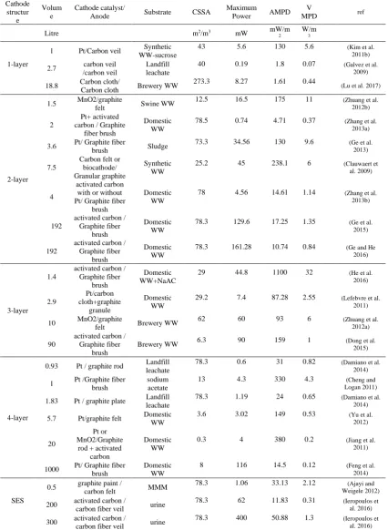
Table 2.2 Summary of practical applications of MFCs
Cathode structur e Volum e Cathode catalyst/
Anode Substrate CSSA
Maximum
Power AMPD
V
MPD ref
Litre m2/m3 mW mW/m
2
W/m 3
1-layer
1 Pt/Carbon veil Synthetic WW-sucrose
43 5.6 130 5.6 (Kim et al.
2011b)
2.7 carbon veil /carbon veil
Landfill leachate
40 0.19 1.8 0.07 (Galvez et al.
2009)
18.8 Carbon cloth/
Carbon cloth Brewery WW
273.3 8.27 1.61 0.44
(Lu et al. 2017)
2-layer
1.5 MnO2/graphite
felt Swine WW
12.5 16.5 175 11 (Zhuang et al.
2012b)
2
Pt+ activated carbon / Graphite
fiber brush
Domestic WW
78.5 0.74 4.71 0.37 (Zhang et al. 2013a)
3.6 Pt/ Graphite fiber
brush Sludge
73.3 34.56 130 9.6 (Ge et al.
2013)
7.5
Carbon felt or biocathode/ Granular graphite
Synthetic WW
25.2 45 238.1 6 (Clauwaert et
al. 2009)
4
activated carbon with or without Pt/ Graphite fiber
brush
Domestic WW
78 4.56 14.61 1.14 (Zhang et al.
2013b)
192
activated carbon / Graphite fiber
brush
Domestic WW
78.3 129.6 17.25 1.35 (Ge et al.
2015)
192
activated carbon / Graphite fiber
brush
Domestic WW
78.3 161.28 10.74 0.84 (Ge and He 2016)
3-layer 1.4
activated carbon / Graphite fiber
brush
Domestic WW+NaAC
29 44.8 1100 32 (He et al.
2016) 2.9 Pt/carbon cloth+graphite granule Domestic WW
29.2 7.4 87.28 2.55 (Lefebvre et al. 2011)
10 MnO2/graphite
felt Brewery WW
62 60 93 6 (Zhuang et al.
2012a)
90
activated carbon / Graphite fiber
brush
Brewery WW 6.3 90 159 1 (Dong et al. 2015)
4-layer
0.93 Pt / graphite rod Landfill leachate
78.3 0.6 31 0.82 (Damiano et al.
2014)
1 Pt /Graphite fiber brush
sodium acetate
13 4.3 330 4.3 (Cheng and
Logan 2011)
1.83 Pt / graphite plate Landfill leachate
78.3 1.19 24 0.65 (Damiano et al.
2014)
5.7 Pt/graphite felt Domestic WW
3.6 3.02 149 0.53 (Yu et al.
2012)
20
Pt or MnO2/Graphite
rod + activated carbon
Domestic WW
0.3 4 380 0.2 (Jiang et al.
2011)
1000 Pt/ Graphite fiber brush Domestic WW 8 116 14.5 0.12 (Feng et al. 2014)
SES
0.5 graphite paint /
carbon felt MMM
78.3 1.06 33.13 2.12 (Ajayi and
Weigele 2012)
200 activated carbon /
carbon fiber veil urine
78.3 62 11.83 0.31 (Ieropoulos et
al. 2016)
300 activated carbon /
carbon fiber veil urine
78.3 400 50.88 1.3 (Ieropoulos et
al. 2016)
CSSA: cathode specific surface area; AMPD: areal maximum power density; VMPD: volumetric maximum power
24
The 2-layer cathode was the most widely used cathode in practical applications (7 cases), followed by the 4-layer cathode (6 cases). There were 4 cases of the 3-layer cathode while 1-layer cathode cases number was equal to SES (3 cases). In terms of maximum power generation, no significant difference was found among the 2-layer, 3-layer, 4-layer and SES cathodes (~102
mW), while the maximum power generated by 1-layer MFCs (8.3 mW) was much lower. In terms of cathode catalyst material, Pt and activated carbon were the most widely used in all these cases (Table 2.2). Both maximum power and power density obtained from activated carbon were higher than those obtained from Pt. The high power generation not only makes a high profit to offset the MFC system cost, but also increases the organic matter removal rate which could reduce the design volume of future MFC-based WW treatment plants. Hence, the low-cost activated carbon has greater potential than Pt for future practical applications.
25
Figure 2.4 PCA biplot for all cases of MFCs’ practical application.
(AMPD=areal maximum power density, VMPD=volumetric maximum power density, CSSA= cathode specific surface area, MP=maximum power, V=volume, CA=cathode area, the red points represent practical application cases, for example, 3L1 represents case 1 of MFC with 3-layer cathode, SES3
represents case 3 of MFC with SES cathode)
The high cost is the primary barrier limiting MFC practical application. The materials and configurations of different MFCs vary significantly. Figure 2.5 showed the cost analysis results. The total cost of 1-layer and 4-layer cathode MFCs was much higher than other MFCs, which was due to the use of high-cost materials such as carbon cloth and Pt. Employed with the mixed 2-layer cathode, the MFC cost (11724 $/m3) was slightly lower than the MFC with 3-layer
cathode (12079 $/m3). The cost of the SES based MFC with 8400 $/m3 is the lowest, which was
due to the use of cheap ceramic materials as a separator and reactor frame (around 4680 $/m3).