Article
A New Input Device for Spastics Based on
Strain Gauge
Niels Buchhold * and Christian Baumgartner *
Institute of Health Care Engineering with European Testing and Certification Body of Medical Devices, Graz University of Technology, Stremayrgasse 16/II, 8010 Graz, Austria
* Correspondence: [email protected] (N.B.); [email protected] (C.B.)
Abstract: This article presents a new input device for spastic patients and others with similar symptoms. The sensor consists of a disc used to determine positions and can replace standard joysticks in medical devices such as electric-powered wheelchairs. Using a standard joystick while operating a powered wheelchair can result in dangerous situations when spastic movements occur and extremities cramp making them uncontrollable. To avoid this, a disc was developed that can be controlled with any body part. By shifting weight (x- and y-axis) the disc can tilt in any direction creating a proportional output signal and can also be pushed down in the center (z-axis) to open a menu on a screen for example. When spasms occur it is impossible for users to get stuck on the input device because the disc is flat and can be mounted within a control panel. Body parts coming into contact with the disc would merely slide across the disc without triggering unintentional actions. The sensor presented here is also adaptive and can be adjusted to fit a user’s strength and range of motion. This proposal aims to develop an input device that enables spastic patients to operate sensitive systems safely.
Keywords: tactile sensors; assistive technologies; power wheelchair; medical systems; robotic; joystick; strain-gauge; spasticity
1. Introduction
The use of sensors as interfaces between man and machine is taking on an increasingly important role in our society. Joysticks and systems similar to joysticks can be operated almost intuitively and can be found in a variety of controller systems as input devices. Fields of application such as medical technology require the highest possible level of safety. Moreover, a wide spectrum of use is necessary for individual users. For people with physical disabilities such as spasticity, using a sensor [1] (joystick) often presents a problem since the range of motion (force and lift) is prone to constant changes and unexpected spasms. Cramped movements when using sensitive systems can result in uncontrollable and dangerous situations. The user can also injure itself, for example, when a hand cramps around a joystick and the bones and tendons are overstrained [2]. When an electric-powered wheelchair is used, new control systems such as eye tracking, voice control, and brain-computer interfaces [3–6] tend to be problematic. Tongue controls [7,8] are only suitable under certain conditions. These types of input methods make it difficult to perform precise and complex control actions simultaneously. Eye tracking is also subject to natural reflexes (eye reflex) and is completely unsuitable as a control method when safety is important. Voice controls can usually only process one command at a time and are unreliable in loud environments [9]. A reliable control test with an electric-powered wheelchair (EPW) is to drive in the shape of a figure 8. Systems that provide users assistance with navigation [10,11] are practical but also costly.
would be prevented. For sporting activities such as EPW hockey, direct controls are preferred. In US patents, [13–15] input devices with strain gauges are described that are fashioned in the form of conventional joysticks. The method of position determination used here is therefore basically known. The explicit innovations concerning known constructions and methods for position determination are listed below:
1. The sensor’s specific flat disc design.
2. The construction and formation of the movement carrier made of carbon fiber reinforced composite.
3. The movement carrier’s high-precision ability to return to its exact position of rest after deflection.
4. The algorithm to customize the device to changed clinical symptoms
5. The differential plausibility test of strain-gauge values to increase user safety. 6. The insensitivity of the sensor during spasticity (loadable up to 1,400 N).
All of these new features are described in this article. This includes the implementation and description of the prototypes’ hardware (Figure 1 and 2) as well as the schematic description of the software and its algorithms.
Figure 1. SGD drawing
2. Hardware of the SGD
2.1 Basic construction
integrated in a control panel in front of the user (EPW operating panel). In this case, for example, the entire control table could be made of CFRP, whereby the table simultaneously represents the sensor material. Due to the interlocking housing parts, the sensor is splash-proof.
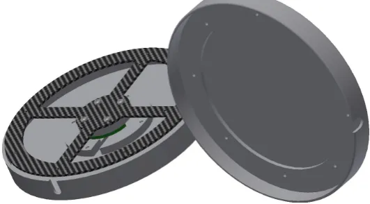
Figure 2. SGD exploded view drawing
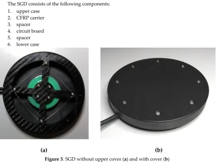
The SGD consists of the following components: 1. upper case
2. CFRP carrier 3. spacer 4. circuit board 5. spacer 6. lower case
(a)
(b)
Figure 4. CFRP carrier with affixed strain-gauges
2.2 CFRP carrier
The CFRP carrier (Figure 4) of the prototype consists of a CFRP plate with a thickness of 1.3 mm. The thickness of the material can be adapted to the application, with CFRP having excellent strength as compared to other materials. Compared to aramid fiber reinforced composite (AFRP) and glass fiber reinforced composite (GFRP), CFRP has superb dynamic properties. The dynamic damping capacity of AFRP under a dynamic load six times higher than GFRP and nine times higher than CFRP [18]. In particular, the reset behavior of the CFRP carrier is important. If the sensor is overloaded, the interlocking housing parts protect the CFRP carrier against damage. Due to the design of the housing, the maximum stroke can be mechanically limited. In case of excessive stress (max. 1,400 N), inflowing forces are then discharged past the CFRP carrier over the housing. The CFRP compensated strain gauges are glued on and then soldered to the circuit board. The circuit board and the strain gauges can finally be covered with an additive-crosslinked silicone. Thus, the sensor can also be used in a humid environment. The CFRP carrier was also tested for tension. The construction shown in Figure 3 with a material thickness of 1.3 mm broke under a tensile load of 102 N. It is impossible, however, to overload the sensor housing in that way without the aid of a tool. The chosen material thickness of 1.3 mm provides a very good compromise between sensitivity and durability.
2.3 Circuit board
2.4 Different versions
Depending on the purpose of use, the sensor can be operated in different variations:
Version 1: The CFRP carrier and its shape are adapted to the expected requirements. In particular, the material thickness and the arrangement of the CFRP fabric coverings are taken into account. The shape also supports the stability and varies the bending stress of the strain gauges.
Version 2: The setup is similar to version 1. In addition, the CFRP carrier is poured into an additive-crosslinked, thermally vulcanizing silicone rubber. Depending on the Shore hardness, the damping properties are thereby varied. Other damping materials, such as compression springs or other polymers, did not bring about the desired effect because the thermal expansion coefficients influenced the CFRP carrier in a counterproductive manner.
Version 3: The entire operating panel (e.g. on an EPW) is made of CFRP. The strain gauges are applied underneath the panel. Milling patterns around the strain gauges then vary the input forces applied by the user.
During the series of tests, CFRP carriers with material thicknesses from 0.45 mm to 2 mm were examined. The shape can also influence and adjust the sensitivity and maximum load and in particular the force required.
3. Sensor operations
3.1 Basics
If external forces act on the CFRP carrier over the upper side of the housing, the angle will change slightly. As a result, the opposing strain gauge is deflected differentially. The resulting differential values can be added to the downstream microcontroller in order to increase the technical resolution. If, for example, a 10 bit A / D converter is used, the resolution increases accordingly.
Example Calculation:
= 512 ; Measured neutral value;
= 640 ; Measured value right strain gauges at t = 1;
= 430 ; Measured value left strain gauges at t = 1;
= | − | + | − |
= 210 Output x-value to the microcontroller
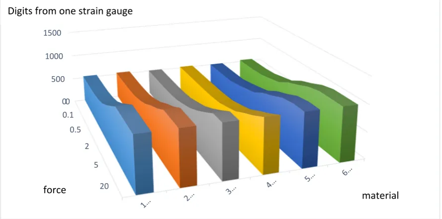
Table 1. Selected measurements with different materials and versions. (only is shown)
Test series force
(N)/digits
diameter disc 110 mm
0 0.05 0.1 0.2 0.5 1 2 3 5 10 20 25
1 Mat. CFRP 0.45 mm
non silicon rubber 532 538 545 561 592 650 760 890 1024 1024 1024 1024
2 Mat. CFRP 0.90 mm
non silicon rubber 535 537 540 551 569 622 698 810 903 1024 1024 1024
3 Mat. CFRP 1.30 mm
non silicon rubber 510 511 513 516 529 550 611 675 776 895 1024 1024
4 Mat. CFRP 2.00 mm
non silicon rubber 521 521 521 521 522 528 549 607 673 790 897 1024
5 Mat. CFRP 0.90 mm
silicon rubber shore 20 505 506 507 511 558 611 670 796 881 982 1024 1024
6 Mat. CFRP 0.45 mm
silicon rubber shore 30 535 537 542 561 614 666 791 873 970 1024 1024 1024
Figure 5. Visualized, measured values from table 1
3.2 Plausibility check
The sensor will also be utilized in highly sensitive or safety related areas, therefore a plausibility check is necessary. For this purpose, in an individual calibration process, all possible measured value combinations of the individual strain gauges are stored in a hash table. If a strain gauge is released from the CFRP carrier, a specific measured value is recorded. In the hash table, a stored value of the opposite, differentially working strain gauge is searched for this measured value. If this value pair does not match the currently measured value pair, then there must be an error. Direct measures are then taken to protect the downstream system from malfunctions.
0 500 1000 1500
0 0.1
0.5
2
5
20
Digits from one strain gauge
3.4 Individually adjustment of the strain gauge disk
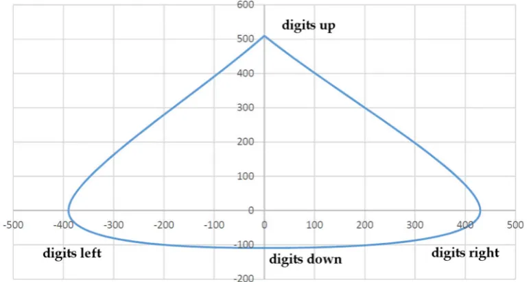
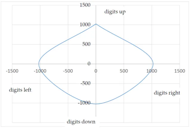
Due to the various symptoms of individual medical conditions, different input forces and input lifts are required. Depending on the specifications, standard joysticks have a pre-determined accuracy (resolution), a certain amount of force is required to deflect it, and a certain stroke to overcome the necessary paths by a fixed amount. As described in the introduction, certain groups of physically disabled people are unable to use standardized joysticks. The issue has to do with this group of individuals’ range of motion in terms of force and stroke. Moreover, the existing range of motion is affected by outside influences such as the ambient temperature [19]. A permanent readjustment of the sensor would be necessary for long-term use. To adjust the sensor to the user’s movement and stroke characteristics, the user moves the SGD at least once with a circular movement in each direction. The z-axis can also be configured by using vertical pressure on the housing cover. The maxima of the x-, y-, and z-coordinates are then saved. The absolute zero position or resting position of each SGD is set during calibration. The calibration process usually takes place only once after production. This avoids higher production costs since the manufacturing allowances are relatively insignificant. As an example, the force or the stroke of a patient was documented. The result in Figure 6 shows an inhomogeneous progression of force applied in different directions.
Figure 6. Force Curve (force to digit), max. value from neutral position Material 3 (see table 2)
When a reference was established (deflection and force to digit) Figure 6 can be used to directly determine the force and stroke the patient applied (see table 2. In a test case, the patient was able to carry out the following deflections, i.e. force (the z-axis is not taken into account here):
Table 2. Patient measurements and applied force.
Direction To Maximum Digits
Approximate Force
forward 510 18.4 N
back 109 2.1 N
left 390 11 N
right 430 14.2 N
Example: Common output values are in the 10 bit range (1024 / value = factor).
Table 3. Maximum patient measurements and calculated output values.
Direction To Maximum
Digits Factor
Calculated Output Values
forward 510 2,007 1024
back 109 9,394 1024
left 390 2,626 1024
right 430 2,381 1024
All of the coordinates documented during use for this user, then have to be converted with the factor to attain a consistent output signal.
Example Calculation:
(Right value see Table 2; 10 bit output signal)
= 430 ; Maximum right direction;
2,381 Calculated factor see table 3;
= 200 ; Example value to the right;
= ∗ Digital output value;
= 476 Digital output;
These initial values are then calculated with the differential output value of the opposite strain gauge, according to the example calculation (see 3.1 Basics). During this time, the plausibility check (see 3.2 Plausibility check) is also performed. By means of the algorithm shown above, the coordinates of the inhomogeneous input forces (see Figure 6) are converted into homogeneous output data (see Figure 7). The user can then, for example, move a computer mouse or an EPW at the same speed in all directions independently of its inhomogeneous force-lifting ratio. The output values calculated by the factor are denoted in Table 3 and visualized in Figure 7.
3.5. Software
The software sequences are divided into two separate processes. To adapt the SGD to the user (see Figure 8), the teach-in-button must be pressed. After the rest values have been determined, the microcontroller stores the maximum values reached for each individual direction. In addition, possible value combinations are stored, which are then used for plausibility checks. After determining all the values mentioned, factors are calculated in order to generate homogeneous output signals (see Figure 7) from the inhomogeneous input signals (see Figure 6). If the rest values are outside a defined range (theoretical rest value +/- 100 digits), an error is generated. This value range serves to balance manufacturing tolerances.
Figure 8. Schematic sensor software teach-in process.
During normal use (see Figure 9), the data of the AD 7811 are first read in via SPI. Then, a plausibility check is performed. In this case, two strain gauges are combined as a pair of values. These pairs of values must match the value pairs stored in the teach-in-process. Thus, a very large portion of all possible errors can be intercepted. In case of an error, the microcontroller sends neutral values to the connected systems and a separate error message is issued via an I/O pin.
3.6. Hardware
The measured output signals (Fig. 10) of the 4 strain gauges are amplified with the respective differential amplifier AD 623 [16]. The analog voltage values are then fed in with an ADC (analogue digital converter) AD 7811[17] and converted into an SPI (slave) bus signal. A microcontroller SPI (master) accepts the data and generates the desired output signals for the connected hardware. The microcontroller also utilizes various input and output signals, which in the event that the SGD malfunctions an emergency signal is sent to an EPW.
Figure 10. Schematic sensor hardware.
4. Results and Discussion
The SGD described here is in the prototype stage. Using CFRP the spring precision is at +/- 1 digit. The climate chamber tests were successfully completed (-30 degrees to 80 degrees) with a deviation of +/- 1 digit. This can lead to a maximum + -2 digits deviation due to external influences. To counteract this problem, a rest window of 5 digits is set in each direction around the neutral parent values. The first tests under laboratory conditions were successfully completed. During the tests, the sensor was used to substitute a mouse and to operate an EPW [20]. As long as a physically disabled patient still has some type of physical capability (hand, finger, foot, head, shoulder, etc.), use of this SGD should be possible. If the disease pattern changes, the SGD can be adapted immediately (without specialist staff) to the user’s new abilities. This learning process takes a maximum of 10 seconds. Especially in countries with poor health systems, using the SGD is beneficial because practically no follow-up costs are to be expected even if the SGD is used by another user with a different medical condition. Due to the weight of the upper housing cover, the SGD can begin to oscillate when a specific frequency acts on the sensor. Thus the system can begin to “vibrate”. This particular case can also occur in off-the-shelf joysticks. In order to prevent this unlikely event, an additive-cross-linked silicone rubber can be poured under the CFRP carrier (version 2), which acts as a vibration damper, alleviating the vibration. Due to the design, the force to be exerted increases exponentially to the deflection, thereby causing a natural force feedback.
In summary, this sensor provides a new input possibility, especially for spastic patients. Injuries or an unintentional invoke of commands due to sudden spasticity are largely avoided. Combined with other recent developments as cited in the introduction, the human-machine interface could be improved for this disease. Due to the simple construction of the SGD, high production costs are not expected. Testing according to the Medical Devices Act has not yet been carried out.
Conflicts of Interest: The authors declare no conflicts of interest.
References and Notes
1. Buchhold, N.; Baumgartner, C. A New, Adaptable, Optical High-Resolution 3-Axis Sensor. Sensors (Basel,
Switzerland) 2017, 17.
2. Hu, X.; Afsharipour, B.; Rymer, W.Z.; Suresh, N.L. Impairment of muscle force transmission in
spastic-paretic muscles of stroke survivors. In 2016 38th annual international conference of the IEEE Engineering
in Medicine and Biology Society (EMBC): IEEE: Piscataway, NJ, 2016, pp. 6098–6101.
3. Wolpaw, J.R.; Birbaumer, N.; Heetderks, W.J.; McFarland, D.J.; Peckham, P.H.; Schalk, G.; Donchin, E.;
Quatrano, L.A.; Robinson, C.J.; Vaughan, T.M. Brain-computer interface technology: a review of the first
international meeting. IEEE transactions on rehabilitation engineering : a publication of the IEEE Engineering in
Medicine and Biology Society 2000, 8, 164–173.
4. Kim, K.-N.; Ramakrishna, R.S. Vision-based eye-gaze tracking for human computer interface. In IEEE
SMC'99 conference proceedings: IEEE Service Center: Piscataway, NJ, 1999, pp. 324–329.
5. Malkin, J.; House, B.; Bilmes, J. Control of simulated arm with the vocal joystick. CHI 2007 Workshop on
Striking a C [h] ord: Vocal Interaction in Assistive Technologies, Games, and More. CHI 2007 Workshop on
Striking a C [h] ord: Vocal Interaction in Assistive Technologies, Games, and More 2007.
6. Malkin, J.; House, B.; Bilmes, J. The VoiceBot: a voice controlled robot arm. Vocal Interaction in Assistive
Technologies, Games, and More. CHI 2007 Workshop on Striking a C [h] ord 2007, 183–192.
7. Buchhold, N. Apparatus for controlling peripheral devices through tongue movement, and method of processing
control signals. US Patent 5460186 A, 24. Okt. 1995.
8. Kim, J.; Park, H.; Ghovanloo, M. Tongue-operated assistive technology with access to common smartphone
applications via Bluetooth link. Conference proceedings : … Annual International Conference of the IEEE
Engineering in Medicine and Biology Society. IEEE Engineering in Medicine and Biology Society. Annual Conference
2012, 2012, 4054–4057.
9. Martens, C.; Ruchel, N.; Lang, O.; Ivlev, O.; Graser, A. A friend for assisting handicapped people. IEEE
Robotics & Automation Magazine 2001, 8, 57–65.
10. Huntemann, A.; Demeester, E.; Poorten, E.V.; van Brussel, H.; Schutter, J. de. Probabilistic approach to
recognize local navigation plans by fusing past driving information with a personalized user model. In
IEEE International Conference on Robotics and Automation (ICRA), 2013, 6 - 10 May 2013, Karlsruhe, Germany:
IEEE: Piscataway, NJ, 2013, pp. 4376–4383.
11. Kim, E.Y. Wheelchair navigation system for disabled and elderly people. Sensors 2016, 16, 1806.
12. Cooper, R.A.; Widman, L.M.; Jones, D.K.; Robertson, R.N.; Ster, J.F. Force sensing control for electric
powered wheelchairs. IEEE Transactions on Control Systems Technology 2000, 8, 112–117.
13. Kamentser, B.; Kamentser, E. Force transducer with co-planar strain gauges. U.S. Patent No. 5,872,320, 16. Febr.
1999.
14. Manara, A.; Scofield, M.C.; Cheal, B. Sensor and circuit architecture for three axis strain gauge pointing device and
force transducer. U.S. Patent No. 6,243,077, 5. June 2001.
16. Analog Devices Inc. AD623 (Rev. E). Available online:
http://www.analog.com/media/en/technical-documentation/data-sheets/AD623.pdf (accessed on 1 January,
2017).
17. Analog Devices Inc. AD7811/AD7812 (Rev. C). Available online:
http://www.analog.com/media/en/technical-documentation/data-sheets/AD7811_7812.pdf (accessed on 1
January, 2017).
18. Ehrenstein, G.W. Faserverbund-Kunststoffe: Werkstoffe, Verarbeitung, Eigenschaften, 2nd ed; Hanser Verlag:
München, 2006.
19. Muscular Dystrophy Association Inc. Facts About Myotonic Muscular Dystrophy. Available online:
https://www.mda.org/sites/default/files/publications/Facts_MMD_P-212_0.pdf (accessed on 1 January,
2017).
20. Dynamic Controls. The DX2 System - Dynamic Controls. Available online:
https://dynamiccontrols.com/en/dealers/products/dx2/the-dx2-system (accessed on 1 January, 2017).
21. Thorp, E.B.; Abdollahi, F.; Chen, D.; Farshchiansadegh, A.; Lee, M.-H.; Pedersen, J.P.; Pierella, C.; Roth, E.J.;
Seanez Gonzalez, I.; Mussa-Ivaldi, F.A. Upper Body-Based Power Wheelchair Control Interface for
Individuals With Tetraplegia. IEEE transactions on neural systems and rehabilitation engineering : a publication of
the IEEE Engineering in Medicine and Biology Society 2016, 24, 249–260.