Compact Implementation of Threefish and Skein on
FPGA
Nuray At
∗, Jean-Luc Beuchat
†, and ˙Ismail San
∗∗Department of Electrical and Electronics Engineering, Anadolu University, Eskis¸ehir, Turkey
Email:{nat, isan}@anadolu.edu.tr
†Faculty of Engineering, Information and Systems,
University of Tsukuba, 1-1-1 Tennodai, Tsukuba, Ibaraki, 305-8573, Japan Email: [email protected]
Abstract—The SHA-3finalist Skein is built from the tweakable Threefish block cipher. In order to have a better understanding of the computational efficiency of Skein (resource sharing, memory access scheme, scheduling, etc.), we design a low-area coprocessor for Threefish and describe how to implement Skein on our architecture. We harness the intrinsic parallelism of Threefish to design a pipelined ALU and interleave several tasks in order to achieve a tight scheduling. From our point of view, the main advantage of Skein over other SHA-3 finalists is that the same coprocessor allows one to encrypt or hash a message.
I. INTRODUCTION
In this article, we propose a novel hardware implementation of the SHA-3finalist Skein [1]. As emphasized by Kerckhofet al., “fully unrolled and pipelined architectures may sometimes hide a part of the algorithms’ complexity that is better revealed in compact implementations” [2]. In order to have a deeper un-derstanding of the computational efficiency of Skein (resource sharing, memory access scheme, scheduling, etc.), we decided to design a low-area coprocessor on a Field-Programmable Gate Array (FPGA). Furthermore, such an implementation is valuable for constrained environments, where some security protocols mainly rely on cryptographic hash functions (see for instance [3]).
Skein is built from the tweakable Threefish block cipher, defined with a256-,512-, and 1024-bit block size. The main contribution of this article is a lightweight implementation of Threefish (Section II). Then, we describe how to implement Skein on our coprocessor (Section III). We have prototyped our architecture on a Xilinx Virtex-6 device and discuss our results in Section IV.
II. THETHREEFISHBLOCKCIPHER
A. Algorithm Specification
Threefish operates entirely on unsigned64-bit integers and involves only three operations: rotation of k bits to the left (denoted by≪k), bitwise exclusive OR (denoted by⊕), and addition modulo264 (denoted by
). Therefore, the plaintext
P and the cipher key K are converted to Nw 64-bit words.
Note that the number of wordsNwand the number of rounds
Nr depend on the key size (Table I).
The key schedule generates the subkeys from a block cipher key K = (k0, k1, . . . , kNw−1) and a 128-bit tweak
Table I
NUMBER OF ROUNDS FOR DIFFERENT KEY SIZES(REPRINTED FROM[1]).
Key size # words # rounds
[bits] Nw Nr
256 4 72 512 8 72 1024 16 80
T = (t0, t1). K and T are extended with one parity word
(Algorithm 1, lines 1 and 2). Each subkey is a combination of Nwwords of the extended key, two words of the extended
tweak, and a counter s(Algorithm 1, lines 5 to 9). Note that the extended key and the extended tweak are rotated by one word position between two consecutive subkeys.
Algorithm 1 Key schedule.
Input: A block cipher key K = (k0, k1, . . . , kNw−1);
a tweak T = (t0, t1); the constant C240 =
1BD11BDAA9FC1A22.
Output: Nr/4 + 1 subkeys ks,0, ks,1, . . . , ks,Nw−1, where
0≤s≤Nr/4.
1. kNw←C240⊕
Nw−1
M
i=0 ki;
2. t2←t⊕t1;
3. fors←0 toNr/4 do
4. fori←0 toNw−4 do
5. ks,i ←k(s+i) mod (Nw+1);
6. end for
7. ks,Nw−3←k(s+Nw−3) mod (Nw+1)tsmod 3;
8. ks,Nw−2←k(s+Nw−2) mod (Nw+1)t(s+1) mod 3;
9. ks,Nw−1←k(s+Nw−1) mod (Nw+1)s;
10. end for
11. returnks,0,ks,1, . . . ,ks,Nw−1, where 0≤s≤Nr/4;
A series of Nr rounds (Figure 1 and Algorithm 2, lines 4
to 19) and a final subkey addition (Algorithm 2, line 21) are applied to produce the ciphertext. The core of a round is the simple non-linear mixing function Mixd,j (Algorithm 2,
in [1, Table 4]), and a bitwise exclusive OR. A word permu-tationπ(i) (defined in [1, Table 3]) is then applied to obtain the output of the round (Algorithm 2, line 17). Furthermore, a subkey is injected every four rounds (Algorithm 2, line 7).
e4,3
f4,3
e4,2
e4,1
R4,0
e4,0
v4,2
Mix
4
,
0
v4,3
v4,0
v5,1
v5,0 v5,2 v5,3
v4,1
k1,0
Mix
4
,
1
Permute
k1,2 k1,3
k1,1
R4,1 ≪
≪
f4,0 f4,1 f4,2
Figure 1. One of the72rounds of Threefish-256.
Algorithm 2 Encryption with the Threefish block cipher.
Input: A plaintext blockP = (p0, p1, . . . , pNw−1);Nr/4 + 1
subkeys ks,0, ks,1, . . . , ks,Nw−1, where 0 ≤s ≤ Nr/4;
4Nw rotation constants Ri,j, where 0 ≤ i≤ 7 and 0 ≤
j≤Nw/2.
Output: A ciphertext blockC= (c0, c1, . . . , cNw−1).
1. fori←0to Nw−1 do
2. v0,i←pi;
3. end for
4. ford←0 to Nr−1do
5. fori←0to Nw−1 do
6. if dmod 4 = 0then
7. ed,i←vd,ikd/4,i; (Key injection)
8. else
9. ed,i←vd,i; (Rename)
10. end if
11. end for
12. forj←0 to Nw/2−1do
13. fd,2j ←ed,2jed,2j+1; (Mixd,j)
14. fd,2j+1←fd,2j⊕(ed,2j+1≪Rdmod 8,j);
15. end for
16. fori←0to Nw−1 do
17. vd+1,i←fd,π(i); (Permute)
18. end for
19. end for
20. fori←0to Nw−1 do
21. ci←vNr,ikNr/4,i; (Key injection)
22. end for
23. return C= (c0, c1, . . . , cNw−1);
B. The UBI Chaining Mode
Let E(K, T, P) be a tweakable encryption function. The
Unique Block Iteration (UBI) chaining mode allows one to build a compression function out of E. Each blockMiof the
message is processed with a unique tweak valueTi encoding
how many bytes have been processed so far, a type field (see [1] for details), and two bits specifying whether it is the first and/or last block. The UBI chaining mode is computed as:
H0←G,
Hi+1←Mi⊕E(Hi, Ti, Mi),
whereGis a starting value ofNw words.
C. Hardware Implementation
This short description of Threefish gives us the first hints on designing a dedicated coprocessor (Figure 2). Our architecture consists of a register file implemented by means of dual-ported memory, an ALU, and a control unit. The register file is organized into 64-bit words, and stores a plaintext block, an internal state (ed,i, where 0≤i ≤Nw−1), an extended
block cipher key, an extended tweak, the constant C240, and
all possible values of sinvolved in the key schedule. Thanks to this approach, the word permutation π(i) and the word rotation of the key schedule are conveniently implemented by addressing the register file accordingly. Since the round constants repeat every eight rounds (Algorithm 2, line 14), we decided to unroll eight iterations of the main loop of Threefish (Algorithm 2, lines 4 to 19). The rotation constants
Rd,i are included in the microcode executed by the control
unit. Note that our register file is designed for Threefish-1024 (i.e. Nw = 16 and Nr = 80). It is therefore straightforward
to implement the two other variants of the algorithm on our architecture.
Port
B
Port
A
Register file (dual-ported memory block)
WE Address
Data
Address
Data
Port A Port B WE
Control unit p0, . . . ,p15
0
16
48 32 ei,0, . . . ,ei,15
k0, . . . ,k15
k16
96 t0,t1,t2,C240
0,1, . . . ,14,15
16,17,18,19,20 112 64
ctrl10:0
Start Idle
Nw
Arithmetic and Logic Unit (Figure 3b)
Figure 2. Architecture of the Threefish coprocessor.
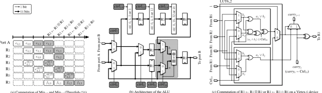
The next step consists in defining the architecture of the ALU and the instruction set of our coprocessor. In the fol-lowing, Ridenotes a 64-bit register. Figure 3a illustrates our scheduling of the two mixing functions Mix4,0 and Mix4,1 of
T o port B 1 0 1 0 0 1 0 1 0 1 0 1 or 1 0 0 1 1 0 1 0 From port B From port A
R4 e≪1
4,1
e≪9 4,1
e4,2
e4,0 e4,3
e4,3
e4,1 e4,3
e4,2
e≪1 4,3
e≪1 4,3
e≪33 4,3
f4,3
f4,1 f4,2
(a) Computation of Mix4,0and Mix4,1(Threefish-256)
carryj LUT6 2 ≪ 0 , 16 , 32 or 48 ctrl7
R5 R
1
ctrl9 ctrl5:4
1 0
carryj+1
aj aj From R 3 From R 1 From R 2 1 From R 6 T o R 3 Ctrl 10
(aj∧bj)⊕Ctrl10
bj a
j∨bj
bj a
j∨bj
(c) Computation of R3←R1R2or R3←R3⊕R6on a Virtex-6device
e≪25 4,1
ctrl6 ctrl8 ctrl10
b a ≪ 0 , 1 , 2 or 3
(carry0=Ctrl10) ctrl1:0
(b) Architecture of the ALU
≪ 0 , 4 , 8 or 12 R3
R4 R5 R6
R2
ctrl3:2
64bits
1bit
R3← R1
R2
R3← R3
⊕R
6
R3← R1
R2
R3← R3 ⊕R 6 Port A R1 R2 e4,1 e4,0 e4,1 R6
R3 f4,0
Figure 3. Arithmetic and logic unit for Threefish encryption.
• The operand e4,1 is loaded in register R1; at the same
time, we start the computation of e4,1 ≪ R4,0; this
operation requires three clock cycles and intermediate results are stored in R4, R5, and R6.
• Then, e4,0 is loaded in register R2; the content of R1 is
not modified (i.e. R1 must be controlled by an enable signal).
• We execute the instruction R3←R1R2.
• R3 and R6 contain f4,0 and e4,1 ≪R4,0, respectively.
The instruction R3←R3⊕R6allows us to computef4,1.
We schedule Mix4,1as soon ase4,0has been read, and manage
to keep the pipeline continuously busy. In summary, our ALU must be able to carry out any rotation of a64-bit word and to perform the following operation (Figure 3b):
R3←
(
R1R2 when Ctrl10= 0,
R3⊕R6 otherwise, (1)
where Ctrl10 denotes a control bit. Our ALU is therefore
similar to the one proposed by Beuchat et al. [4] for the SHA-3 finalist BLAKE, and we can take advantage of their strategy to share hardware resources between the adder and the array of XOR gates (we propose here a more general approach that does not require a low-level VHDL description relying on libraries provided by Xilinx). Let us define two64-bit operands
aandbsuch that:
(a, b) = (
(R1,R2) when Ctrl10= 0, (R3,R6) otherwise.
It is well-known that ab = (a∨b)(a∧b) and a⊕ b= (a∨b)(a∧b), where∨,∧, anddenote the bitwise OR, the bitwise AND, and the subtraction modulo264of two
operands, respectively [5]. Thus, Equation (1) can be rewritten as follows:
R3←(a∨b)((a∧b)⊕Ctrl10)Ctrl10. (2)
Figure 3c describes the implementation of Equation (2) on a Virtex-6device. Since there is a single control signal to choose the arithmetic operation and to selectaandb, Equation (2) in-volves only five variables, and is advantageously implemented by64LUT6 2 primitives and dedicated carry logic.
In order to reduce the number of operands stored in the register file, we interleave the key schedule (Algorithm 1) and the encryption process (Algorithm 2). This approach allows us to generate the subkeys on-the-fly. It is however necessary to computet2andkNw before the first key injection. The easiest
way to compute t2 would be to load t0 and t1 in registers R1 and R2, respectively, and to execute the instruction R3←
R1⊕R2. Unfortunately, this solution requires one more control bit to select the inputs of the arithmetic operator, and it is not possible to implement the multiplexers and the adder on the same LUT6 2 primitive anymore. Since the critical path of our coprocessor is located in the 64-bit adder, an extra level of LUTs would decrease the clock frequency. However, we are able to compute t2 using only the functionalities defined
by Equation (1). Since t2 = (t00)⊕(t1 ≪0), it suffices
to execute the following instructions:
R4←t1≪0,
R1←t0, R2←0, R5←R4≪0,
R3←R1R2, R6←R5≪0,
R3←R3⊕R6.
This approach assumes that we can read simultaneously two values from the register file. Thanks to the multiplexer con-trolled by Ctrl7, we can load data from port A or port B
into register R2 (Figure 3b). A similar strategy allows us to
compute kNw.
The implementation of the key injection is more straightfor-ward. Note that the multiplexers controlled by Ctrl6 and Ctrl8
allow us to bypass the register file and to use the content of R3 as an input to the ALU. Let us consider for instance the first key injection of Threefish-256: e0,2 is defined as p2k0,2=p2k2t1 and is computed as follows:
R1←k2, R2←t1,
R3←R1R2
R1←R3, R2←p2,
R3←R1R2.
v4,1
@v4,2
@e0,2
R3←R3⊕R6
R3←R1R2 Permute Port A Port B Output B Output A Address A Address B Input B Re gister File ALU R1 R2 R6 R3 Rename
v4,2
@v4,2
e3,2
t2
k1
1 k4
e4,2
@k3
e1,0
Second round Permute Port A Port B Output B Output A Address A Address B Input B Re gister File ALU R1 R2 R6 R3 Rename Fourth round
@e3,0
e≪3,15 e3,0
e≪2,123
f2,1
v3,3
e3,3
f2,0
v3,0
e3,0
e2,0
e2,1
e≪1,357
f1,3
v2,1
e2,1
f1,2
v2,2
@e2,2
e2,2
e2,2
e3,3
v3,2
@k1
k1
e3,1
@e3,0
e2,1
@e1,0
f0,2
v1,2
e1,1
e1,2
e1,3 e1,3
v1,1
f0,3
e1,2
e≪0,316
Third round Fifth round
@0
@C240
@k2 @k3
0
C240
k2 k3
0
C240
k1 k2 k3
k0
C240
C240
@k4
k4
k4
k1 k2 k3
k0 0
k1 k3
k0 0 @k0
k2
k1
k0
@k1
t1
0
0 t0
@t2
@0 @t0
@t1
0 t0 t1 t0 t1 t0 t2
@p3
@k0
k0
p0 p3
k0 k3
p0 p3
k0 k3
p0 p3
@k3
@e0,3
e0,3
@e0,0
e0,0 e0,2
@p1 p1 p1 t0 k1 t0 k1
e0,3 k0,2
e0,0 e0,2 k0,1
t0
k1
k0,2
p2
t1
k2
t1
k2 p2
t1
k2 p2
@p2
@t0
@k1
@t1
@k2
@p0
k3
e≪14 0,1
f0,1
v1,3
e1,3
e0,3
e0,2
@e0,0
e1,0
f0,0
v1,0
e1,0
e0,1 e0,1
k0,1
@e0,3@e0,2
e0,3
e0,3 e0,2
e0,2
e0,3
e0,1
e0,1
p1
@e1,0
e0,0
e0,0
e0,0 Computation oft2andk4, and first key injection
First round Second key injection
t1 k3 t1 t1 k2 k2 k3
k4 k3
e4,3−1 e4,0
t2 1
k1,2
@e4,2
e4,3 e4,2
@e4,3
e4,3 e4,2
@e4,2
e4,2
e4,3
e4,2
@e4,0
@e5,0
e5,0
e≪4,125
v5,3
e5,3
f4,0
v5,0
e5,0
e4,0
e4,0
e4,1
k1,1
v4,2
v4,2 k2
e4,0
@t1
@k2
@e4,0
@v4,1
e4,0
f4,1
t2 1
e4,3−1 v4,2
k1,2
v4,1
k1,1
v4,3
v4,1
v4,1
@e4,3
e4,3
e4,1 e4,1 e4,3 e4,3
f1,0
v2,0
e1,0
e1,0
e2,0
f1,1
v2,3
e2,3
e≪1,152 e1,1 e1,1
f2,2
@e2,2
e2,2
e3,2
f2,3
v3,1
e3,1
e≪2,340 e2,3
e2,3
e2,2
e2,2
f3,1
v4,3
f3,0
e3,0
e3,0
e3,1
e3,0
v4,0
@k4
@1 @t2
v4,0
k1
k4
e≪3,337
f3,3
v4,1
f3,2
v4,2
e3,3
@v4,1
t2
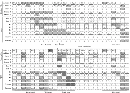
Figure 4. Scheduling of Threefish-256. @ddenotes the address of the64-bit worddin the register file. “Rename” and “Permute” refer to lines 9 and 17 of Algorithm 2, respectively.
The UBI chaining mode can be combined with the final key injection of Threefish encryption. It suffices to modify line 21 of Algorithm 2 as follows:eNr,i←vNr,ikNr/4,iandci ← eNr,i⊕pi. The only difference between this operation and the
mixing function MIXd,j is that no permutation is applied to
the second operand of the bitwise exclusive OR.
The control unit consists of an instruction memory, a small table to generate the address ofk(s+i) mod (Nw+1) during the
key schedule (Algorithm 1), and a simple finite-state machine. Since we unroll only eight rounds, we manage to keep the instruction memory compact. In the case of Threefish-512, we need for instance145instructions and881clock cycles to encrypt a plaintext block in UBI mode.
III. SKEINHASHING
In this work, we focus on the simple Skein hash computation and refer the reader to [1] for a description of the other modes of operation. Three UBI invocations allow one to compute the digest of a messageM = (M0, M1, . . . , Mb−1) of up to299−8
bits, where eachMiis a block ofNw64-bit word. We explain
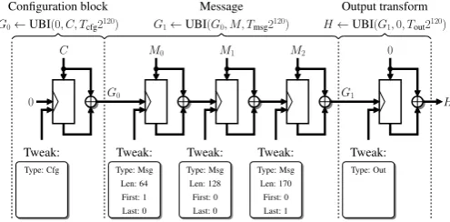
this process with an example: how to hash a message of 170 bytesM = (M0, M1, M2)with Skein-512-512 (Figure 5):
1) Configuration block. The 32-byte string C encodes the desired output length and several parameters de-fined in [1]. In the simple hashing mode, G0 =
UBI(0, C, Tcfg2120)depends only on the output size, and
can be precomputed (see [1, Appendix B]).
2) Message. Note thatM0andM1contain64bytes of data each, andM2is the padded final block with42bytes of data. The tweak encodes whetherMi is the first or last
block ofM, and the number of bytes processed so far. In this example, UBI(G0, M, Tmsg2120)requires three calls to Threefish-512.
3) Output transform. The call to UBI(G1,0, Tout2120)
achieves hashing-appropriate randomness. If a single output block is not sufficient, several output transforms can be run in parallel [1].
and to perform the output transform. In the case of Skein-512 -512, the throughput is given byT = (b512+1)·b··881f bits/s, wheref
denotes the clock frequency of our architecture.
Type: Msg Len: 64
First: 1 Last: 0
M0 M1
C M2 0
G1←UBI(G0, M, Tmsg2120)
G0 G1
H←UBI(G1,0, Tout2120)
H
G0←UBI(0, C, Tcfg2120)
0
Type: Cfg
Tweak: Tweak: Tweak: Tweak:
Type: Msg Type: Msg Type: Out Len: 128
First: 0 Last: 0
Len: 170
First: 0 Last: 1
Configuration block Message Output transform
Tweak:
Figure 5. Processing a3-block message using Skein-512-512in the simple hashing mode.
IV. RESULTS ANDPERSPECTIVES
We captured our architecture in the VHDL language and prototyped a fully autonomous implementation of Skein-512 -512 on a Xilinx Virtex-6 FPGA. Table II summarizes our results and the figures published by other researchers focusing on compact coprocessors (we refer the reader to the SHA-3 Zoo [12] for an overview of high-speed designs). Note that we considered the least favorable case, where the message consists of a single block, to compute the throughput. If we increase the size of the message, the throughput of our coprocessor converges asymptotically to 160 Mbits/s. The other hardware architectures of Skein reported in Table II make a single call to Threefish-512 and do not perform the output transform. Let us assume that all SHA-3 finalists provide the levels of security expected by the NIST. Then, according to Table II, BLAKE, Keccak, and Skein seem to be the best candidates for compact implementations on FPGA. Beuchatet al. [4] designed a low-area ALU for BLAKE on Xilinx devices. However, the datapath depends on the level of security one wishes to achieve. In order to overcome this drawback, Yamazaki et al. [7] proposed a unified coprocessor for the BLAKE family. Their ALU is built around a64-bit datapath, and can process a512-bit block (BLAKE-512) or two256-bit blocks in parallel (BLAKE-256). From our point of view, the main advantage of Skein over other SHA-3finalists is that the same coprocessor allows one to encrypt or hash a message. We plan to improve our architecture in order to support Threefish decryption, Skein-MAC, and tree hashing with Skein.
REFERENCES
[1] N. Ferguson, S. Lucks, B. Schneier, D. Whiting, M. Bellare, T. Kohno, J. Callas, and J. Walker, “The skein hash function family (version 1.3),” Oct. 2010.
[2] S. Kerckhof, F. Durvaux, N. Veyrat-Charvillon, F. Regazzoni, G. Meurice de Dormale, and F.-X. Standaert, “Compact FPGA imple-mentations of the five SHA-3finalists,” inProceedings of the ECRYPT II Hash Workshop, 2011.
[3] J. Zhai, C. Park, and G.-N. Wang, “Hash-based RFID security protocol using randomly key-changed identification procedure,” inComputational Science and Its Applications–ICCSA 2006, ser. Lecture Notes in Com-puter Science, no. 3983. Springer, 2006, pp. 296–305.
[4] J.-L. Beuchat, E. Okamoto, and T. Yamazaki, “Compact implementations of BLAKE-32 and BLAKE-64 on FPGA,” in Proceedings of the 2010 International Conference on Field-Programmable Technology– FPT 2010, J. Bian, Q. Zhou, and K. Zhao, Eds. IEEE Press, 2010, pp. 170–177.
[5] H. Warren,Hacker’s Delight. Addison-Wesley, 2002.
[6] J.-P. Aumasson, L. Henzen, W. Meier, and R. Phan, “SHA-3 proposal BLAKE (version 1.4),” Jan. 2011.
[7] T. Yamazaki, J.-L. Beuchat, and E. Okamoto, “BLAKE-256,
BLAKE-512のコンパクトな統合実装,”IEICE暗号と情報セキュリティ実装
技術小特集号, vol. J-95A, no. 5, 2012.
[8] B. Jungk, “Compact implementations of Grøstl, JH and Skein for FPGAs,” inProceedings of the ECRYPT II Hash Workshop, 2011. [9] G. Bertoni, J. Daemen, M. Peeters, G. Van Assche, and R. Van Keer,
“Keccak implementation overview (version 3.1),” Sep. 2011.
[10] ˙I. San and N. At, “Compact Keccak hardware architecture for data integrity and authentication on FPGAs,”Information Security Journal: A Global Perspective, 2012.
[11] K. Latif, M. Tariq, A. Aziz, and A. Mahboob, “Efficient hardware implementation of secure hash algorithm (SHA-3) finalist - Skein,” in Proceedings of the International Conference on Computer, Communica-tion, Control and Automation–3CA2011, 2011.
Table II
COMPACT IMPLEMENTATIONS OF THE FIVESHA-3FINALISTS ONVIRTEX-5ANDVIRTEX-6FPGAS.
Algorithm FPGA [slices]Area 36k memoryblocks Frequency[MHz] Throughput[Mbits/s]
Aumassonet al.[6] BLAKE-256 xc5vlx110 390 – 91 412
Beuchatet al.[4]† BLAKE-256 xc6vlx75t-2 52 2 456 194
Aumassonet al.[6] BLAKE-512 xc5vlx110 939 – 59 468
Beuchatet al.[4]† BLAKE-512 xc6vlx75t-2 81 3 374 280
Kerckhofet al.[2] BLAKE-512 xc6vlx75t-1 192 – 240 183
Yamazakiet al.[7] BLAKE (unified coprocessor) xc5vlx50-2 138 3 342 2×264150(BLAKE-(BLAKE-512256) )
Jungk [8] Grøstl-256 xcv5 470 – 354 1132
Kerckhofet al.[2] Grøstl-512 xc6vlx75t-1 260 – 280 640
Jungk [8] JH-256 xcv5 205 – 341 27
Kerckhofet al.[2] JH-512 xc6vlx75t-1 240 – 288 214
Bertoniet al.[9] Keccak[r= 1024, c= 576] xc5vlx50-3 448 – 265 52
Kerckhofet al.[2] Keccak[r= 1024, c= 576] xc6vlx75t-1 144 – 250 68
San & At [10] Keccak[r= 1024, c= 576] xc5vlx50-2 151 3 520 501
This Work Skein-512-512 xc6vlx75t-1 132 2 276 80
Jungk [8]‡ Skein-512-256 xcv5 555 – 271 237
Kerckhofet al.[2]‡ Skein-512-512 xc6vlx75t-1 240 – 160 179
Latifet al.[11]‡ Skein-256-256 xc5vlx110-3 821 Not specified 119 1610