Seismic Evaluation, Analysis and Upgrading of Structures of Bohunice Vl NPP
K.H.Rashkov 1), T.Grief 2), H.Schlund 2), J.Kuzma 3) 1) EQE-Bulgaria, Sofia, Bulgaria
2) Siemens KWU, NDM5, Erlangen, Germany 3) EBO, V1
ABSTRACT
Nuclear Power Plant "Bohunice" is situated in the west part of Slovakia. EQE-Bulgaria under contracts with Siemens AG took part in Bohunice V1 Gradual Reconstruction Project in the field of seismic evaluation and analysis of structures and equipment.
The aim of the project is to upgrade Bohunice V1 NPP up to an internationally accepted level of safety for the residual plant life.
The paper presents upgrading concepts, modeling of the structures, solving of problems and the implementation of results of seismic upgrading of the Ventilation Stack and Bridges between Reactor Building, Auxiliary Building and Administrative Building.
I N T R O D U C T I O N
The paper reviews the results of seismic evaluation, modeling of the structures, conducting seismic analysis, checking of the existing structural elements and sizing of new upgrading members and their connections to the existing structures.
The methodology of this analysis is based on Siemens developed design criteria, procedures and application rules for seismic design and evaluation of structures in correspondence with the IAEA Safety Guides and applicable national and international codes and standards. The intension of the application criteria is to provide that no collapse or damage of the structures of the Main Building Complex will occur during or after a seismic event, and will jeopardize important safety- related systems.
As a final assessment on the site seismic evaluation and design for SC1 structures and structural members for one earthquake corresponding to the SL-2 a site-specific response spectra by Slovak Academy of Sciences was performed. This response spectrum is called Review Level Earthquake (RLE). It is characterized by the ground spectra with a horizontal zero- period acceleration of 0.3g, a vertical zero-period acceleration of 0.2g and return period of 10'000 years.
For more precise design in some cases Time History analysis was used. Response Spectra and free-field Time Histories are characteristics of RLE.
For design criteria of SC2B structures whose damage will not affect to the safety-related functions of any of the SC1 structures, systems and components were evaluated and designed using Slovak National Standards.
DESCRIPTION OF THE STRUCTURES
There is no safety-related equipment, piping, or ducting located inside the Bridges and the Ventilation Stack. Seismic concerns arise from potential seismic interaction to safety-related ducts, piping lines, Diesel Generation Building, Reactor Building and cooling water pipes.
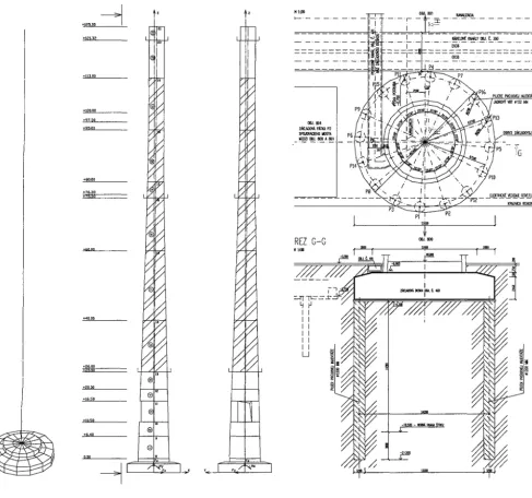
The Ventilation Stack is part of the Reactor Building exhaust system. The Stack was designed and constructed circa 1971 as reinforced concrete structure 125m high above grade, supported on a single circular reinforced concrete foundation 15.4m in diameter at -4.30m from grade. The Stack cross section is 895cm outer diameter ring at the base that reduces to 442cm at top. Wall thickness varies from 47cm at base to 21cm at the top. The Stack foundation undergoes a continuous displacement due to local soil foundation behavior, from which results a slight incline about 58cm at top of the Stack. Figure I shows finite element model and the upgrade of the Stack structure.
SMiRT 16, Washington DC, August 2001 Paper # 1432
__l
, ... tl _1__ _L
/
5,
/
+ioo.oo
+97,~o /
+95.00
/,//
/ ! /
... ~ ,
4-75,30 I
/ / /
h
," ~f, /
//¢
//¢
/
...
////
, a s . o o L / I I
®
+20,00
le
+10.50
0,00
11
14 H00 - . F - ~ - I - . . ~ OBJ. 801 ~ A
. . . ,, r -%.~, . . .
- ..... ~ J - 1 - - - - - -
" ~ ' ~ I - - KkSEtll¢~ KANALY 06&, C. 350
I ~ . ~ . ~ . . . . . . . . . . .
I NS , ~ i
I ~ . ' ( ) p~6
"i ,IAIIR0qR VRI 1152 MM
~ A PkTIO, P2 1 . I I ~ . \~ 4
- : ~ ~"-' ~ - ~ I ~ - ' I ,;--
Pi L _
\ < . x , . , y . . P10
- ~ ~ ELEX1RICK~ VEDENIE OSl/Ell.Em KRAJNI~ KOk4t,NKI¢IE P2
P3
i
"T
i
REZ G-G ~ 0~.~0
=--TT-T~----~----Y"//,I I 1"7 x -j,
I I )" ,['x'x~t~~// / / / ~ / ~
)I)
"i INN'I/
i~"i.~
~
)ll
'
)I'
3-D model Upgrading along the Stack height Upgrading of Stack foundation Fig 1 Ventilation Stack
X
, % /
" ' ~ c~ .T~
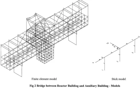
Finite element model Stick model
Fig 2 Bridge between Reactor Building and Auxiliary Building - Models
6,00
~ EXISTIN~
CO'UM._.______SS
~ EXISTING
COLUMNS
/
\
\
EXISTING SLAB \ FOUNDATIONFoundation of the Bridge New shear walls at middle foundation
Fig 3 Bridge between Reactor Building and Auxiliary Building- Structure details
/
(I fa,eb~ l l r i ~ l l ~ l l~vudn~mu n~luu
Finite element m o d e l
IL:~l 1200 lifO0 1200 1200 1200 1200 tk>OO I L l O 0 1200
l-~-f f '~-f '2~-~C'~" :."-~-%~-~-1-L~ '--~-~-:~"t:~-.f '~"-t ~ r :~r:~'ql ... ":~-~ f '~-tt~~--t ~--I :-~-~ t : ~ ~ --t----~---'1---~1--~ .... ~ ... t ... ' O ~ u w # ~,o~te.~e e~osto -~--4~ Po~uvnO ~ c t e n i e ~ o s t a
... . ."l . . ;; ;; ;; iI II -]
l I!.. II II II II I1" :I
~'- . . t II II II II II :'
l-]-i,l-l ii!i ] t Iiill ]i] Ill l ii [ Jlil! M ! I :
i n I I z o ; ~ . i l 7~LSOxSl. / z o s l l n i l 7xLSOxS! /
III Prev(~dzkov~ budov~ !i . . . ' . . . .
I I I " I I . . . proi~l t w U i a .
III ::,~.. tl "-~'~"~ I,
r _ ... =::--' t - l i - v - ,
",
+11 400 ... :"_:1 .... " ... U __D
• ~:,0o ill !,."!:!fLit<. -.11 . . ' @ ~
II1:1' !i!i!i!!!.'lUii , ~ = t ,,,0 :!~'..~tll , ~ ,~.~
... ~" ... " '~"
~
;" :II~./._l\'lt-l_x-Ji~
~
4---,~00 i ~ i ~ °°'"°
~ i l ~ ~ u - c - _ _ ~
~_ ~ s ; : ~ : ~ - - -
. . . ° ' ~ ~ ~ " °... ' " ~ !i!i!iili!i .... ! 1 \ ' ~ . . . . ~ " " \
I ":'c'~j--
----! --'~..~
. . . . :::::!:.~[: s t ~ " I I iiiiii!iti!t
. . . s l , i ~ _ _ _ ~ . : : J I N I N t , =~__'~.._==~'n":" . . . . .
.... ~J V ... / I Ix. . !~,;llit . I
. . . I I \ r t ~ o J n l ~ = t ~ -" r ; . " l ' " ' I I " \ l l u l l l i ' l t : ' ~ prill'telidov.cl', . - " l,.i I
;lll~lilhld V lieI~o~h prll.iiov nc~cn kontlcukci7 I I 'r~l~lne /demonlo~ol o po osoOJn; o ~ r e r , ;
~x
~O~¢h kon~lhuk£i[ ZoplccllOvo( ltO~ink, plechom V~;. ,~ !~10~U p g r a d i n g design
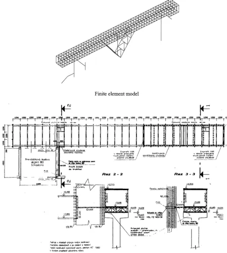
Fig 4 Bridge between Reactor Building and Administrative Building
U P G R A D I N G C O N C E P T S
The seismic strengthening concept has b e e n developed with the idea o f m a x i m a l use o f the elements of the existing building structures and short load path to the foundations. The vertical lateral force resisting systems at the beginning have to be elements with proving properties only.
A key factor for the selection of a specific upgrading concept is the customer's requirement to implement structure upgrades quickly and easily without required breaks in their technological process. That is why usually steel is preferred as material for the construction of upgrading elements.
At some places it is imposed to use both materials - steel and concrete. The application of concrete structures is connected with: longer period of construction, "wet processes", dismounting of existing equipment, influence of weather and enough place for the formwork. So, the implementation of concrete as material for upgrading steel or civil structures (predominantly new shear walls) is limited only for buildings where all these requirements can be satisfied.
M O D E L I N G OF T H E S T R U C T U R E S
The models and the spectral analysis of the structures were generated using the Structural Analysis Program (SAP 2000) computer code.
The preparation for the computer modeling starts with a thorough investigation of the existing structure. This includes study of the existing design and erection documentation and finally - comparing with the results from walkdowns.
Based on as-build documentation and the walkdowns were made computer 3-D finite element models of the structures. The models were generated for the evaluation of the seismic response of the existing structures and for the structures seismic strengthening. For each structure they are composed of two separate main models: a stick model and finite element model. Each of them includes a lot of variants for upgrading - different configuration of braces, shear walls, ties to nearby structures and strengthening of same structural elements. The Soil represented by half-space spring elements with different values. The final detailed 3-D finite element models were modified to reflect the final seismic strengthening, imposed after preliminary calculation of the D/C ratios of the structural elements and specifying of the elements.
The static loads were defined on the basis of the design information and verified by walk downs. The dead weight of the structural elements was determined on the basis of the specific weight of the structural materials specified in the drawings. The equipment was considered in the models as concentrated loads in structural nodal point or was included as additional loads at shell or frame self loads. The snow load was defined according to the design values indicated in the documentation.
The masses for the dynamic calculations were determined on the basis of the defined loads, as follows: 100% dead weight, 100% stationary equipment, 25% snow load, 25% live load.
The principal load combination that was used is:
DL + 0.25 * LL + E (1)
DL - dead load (including equipment loads) L L - live load (including snow load)
E - seismic load (combined by SRSS method)
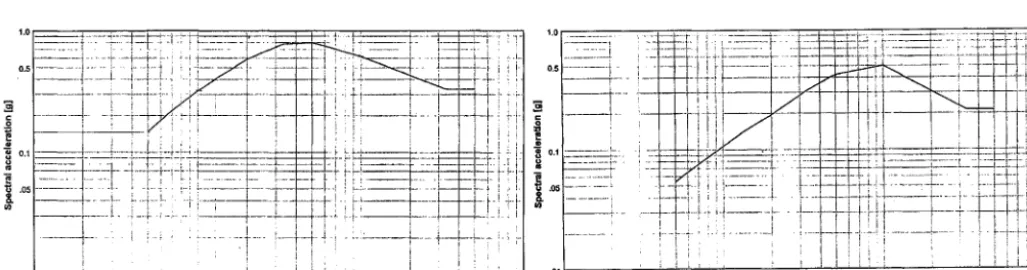
The seismic input has three components, two horizontal components along the model axes X and Y, coinciding with the structure global axes and one vertical component along the model axis Z.
Plots of the spectra are given on Figure 5.
, . 0 1 ~ . _ _ . ~ . ~ . : _ % . : . ~ = ~ : . ~ . : . ~ . ~ = : ~ : . . 1 4 . . _ _ = _ . _ _ . . ~ : _ . . ! - : : ~ i-~ ,~-I . . . _ . . . .... ~ . . . : ~ - - ~ - ~ - -' . . . ' . . . ~ - * ... '
N
' / ~ ~ - . , , : -,1 i , l [ ~ I~' ~
' H ! /
i
' ! l l l ~0.1 ~ ~
I --- ---~ . . . . ~--~~ . . . ~~-' ' :-~""l ~ .. ~ . . . . ~-~..: ... ' '- ... ÷:-:~ ... ~.-- ~-,--i---,i
.o . . . I- '~ ~ t - , ~-: . . . ~- . . . . . - - i i ~ . . . r - ' - r ' - ~ ~ : ; ^ .08
1
0 , - - ~ • ~ • . . • I ; , ' . . . • . ; , ; ~ i ; I . % ,
• 0.1 " 1 , 0 10 100 1.0 10 10(
Horizontal response spectrum Vertical response spectrum
I M P L E M E N T A T I O N SOLUTIONS OF THE SEISMIC U P G R A D I N G DESIGN
During the site visit of Bohunice, the structures were reviewed with visual inspections. The purpose of the review was to verify the as-build conditions of structures and the possibilities for upgradings. The following findings were made:
o Inadequate concrete cover was noticed at a few locations of the concrete structures. Shear ties and vertical reinforcing were exposed at these locations with signs of rust;
o The facade panel connections to the columns don't include any safety detail;
o The Stack structure undergoes continuous displacements due to local soil foundation behavior. The horizontal displacement at top of stack tube was about 58cm.
During the seismic upgrading of structures, the following problems and effects were met:
o During the strengthening of Stack and Bridge 800-801 which are nearby, due to safety reasons the works must be done during night;
o During strengthening of Stack tube with dry splash concrete, some work must be done during night because of high temperature during day;
o During strengthening of Stack foundations, the tilting of the Stack grew up to 60cm;
o During strengthening of Stack tube by new reinforced concrete ring on the outside of the Stack tube, the strengthening of concrete in zone new-old concrete was difficult to be reached;
o All upgradings have to be fulfilled in due time, depending on the deadlines given by the customer and by the plant operating department;
o Not to have any risk to be out of deadlines with upgrading a detailed expediting was installed. CONCLUSIONS
The following activities were performed to accomplish the objectives of the project: o Study of existing documentation
o Detailed walkdowns to study as-built condition and possibilities for strengthening concepts; o 3-D modeling;
o Seismic response and Time History analysis;
o Capacity evaluation of the structures and they foundations; o Development of strengthening concepts;
o Work out project for realization; o Quality control and expediting.
As a result of that project, SC2A-structures were upgraded up to an internationally acceptable Seismic Safety Level. R E F E R E N C E S
1. "Determination of the Review Level Earthquake (RLE) Characteristics for the Bohunice Nuclear Power Plant Site" RNDr. Peter Labak, Doc. RNDr. Peter Moczo, CSC. Bratislava, February 1998.
2. "Seismic Qualification and Design", part A Civil Structures, Work Report, consortium REKON Siemens-Vuje, 1996.
3. "Seismic Upgrading of Ventilation S t a c k - obj.460", Consortium REKON Siemens-Vuje, March 1999.
4. "Seismic Upgrading of Bridge between obj.800 and obj.801 -obj.804", Consortium REKON Siemens-Vuje, March 1999.
5. "Seismic Upgrading of Bridge between obj.800 and obj.803", Consortium REKON Siemens-Vuje, 1999. 6. Slovakian Seismic Standard "STN 730036, Seismic Loading of Structures" Bratislava 1997.
7. Slovakian Seismic Standard "STN 731201, "Design of Concrete Structures", Bratislava 1986. 8. Slovakian Seismic Standard "STN 731401, "Design of Steel Structures", Bratislava 1997.