Division IV
SIMULATION OF EXTERNAL FLOOD ROUTING INSIDE PLANT BUILDING USING FLUID STRUCTURE INTERACTION TECHNIQUE
Rakesh Edumukkala1, Sandeep Alajpur1, Sourav Acharya1, Ajai S Pisharady1, A. D. Roshan1 and L. R. Bishnoi1
1 Siting & Structural Engineering Division, Atomic Energy Regulatory Board (AERB), Mumbai, India
ABSTRACT
External flood pose a definitive challenge to safety of nuclear power plants (NPP), situated at coastal areas, solely due to their ability to induce common cause failures. Various flooding incidents including Fukushima event, indicated the importance of external flooding as an important contributor to nuclear plant risk. Therefore, study of plant response under extreme external flood is necessary as a part of safety assessment. AERB worked on a methodology for probabilistic safety analysis (PSA) due to coastal flood. To investigate the effect of a tsunami induced coastal flooding on NPP components, it is necessary to first route the flood to the site and then within the plant buildings. This requires simulation of tsunami propagation from source to near shore, flood inundation from near shore to plant site and routing of flood water inside the plant. The flood inundation modelling from coast to plant is carried out using MIKE (2016) software to estimate flood height and velocity time histories at entry of various plant buildings. Routing of flood water within a typical safety related building is the objective of present work. Time variation of flood height and velocity at entry to the building is obtained from flood inundation model analysis from MIKE. Flood routing within the building is solved as a fluid structure interaction (FSI) problem using Coupled Eulerian Lagrangian (CEL) technique of ABAQUS (2014) software. Numerical simulations are done for various heights and velocities of flood water at building entry point and result for one simulation is presented in this paper. The flood water is routed into the building and assessment of submergence and flow velocities is done at different floors/basements.
INTRODUCTION
Nuclear power plants are located near a body of water as they require a reliable source of water supply for core cooling purpose. Lack of core cooling in a nuclear reactor can result in accident condition leading to release of radioactivity into the atmosphere. However, due to its ability to cause common cause failure, water can quickly turn dangerous when floods occur due to cyclone, Tsunamis etc. Flooding can damage plant's electrical systems, disabling its cooling mechanisms. This is what happened at the Fukushima Dai-ichi plant in Japan as a result of the March 2011 tsunami, causing severe damage to the reactor.
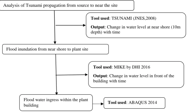
In this study, Tsunami propagation is conducted in three stages, described in Figure 1. From the source, Tsunami propagates inland as a series of waves. Modelling of Tsunami propagation from source to near shore is done in TSUNAMI (JNES, 2008) software and the results are generated at 10m depth of sea, near the shore. MIKE (2016) software is used to simulate the flood inundation from near shore to the plant site. Numerical simulations are carried out in MIKE software to transfer the wave heights obtained at 10m depth from TSUNAMI model to the plant site, also capturing in detail terrain characteristics. With different wave profiles as input from sea, water level and velocity in front of the structure identified for flood routing study, is generated using MIKE software.
propagation inside the plant building is carried out using ABAQUS CEL technique. Wave heights and velocities varying with time are generated in MIKE software in front of the building are used an input to carry out flood routing studies. Figure 1 describes general flow chart explaining step by step method followed for simulation of Tsunami from source to near shore, flood inundation from shore to plant site and flood routing inside the building. Also different tool used and output obtained from them is also mentioned in the flow chart.
Figure 1. Flow chart for tsunami water propagation from source to water ingress within a structure
FLOOD INUNDATION FROM NEAR SHORE TO PLANT SITE
A detailed assessment of tsunami hazard at Indian coast following deterministic approach conducted (Roshan et. al., 2016) considering worst-case scenario tsunamis shows that the specified grade level of the plant is much above the estimated tsunami levels. However, as the intent of the current study is to capture the tsunami propagation ranging from a scale of macro model to micro model, the tsunami scenarios are required to be arbitrarily scaled up so as to observe water flow above the grade level. 16 maximum potential waves were identified and these are scaled up to be used as input waves to carry out the simulations of flood inundation in and around plant site. A numerical model covering terrain data and bathymetry data with a mesh size of 6m-200m resolution is developed. The selected tsunami wave are used as inputs at model boundary (at 10m depth of water in sea) to carry out the simulations. MIKE software developed by DHI is used to carry out this exercise. The wave propagation in sea was also verified by comparing the MIKE model output with TSNUMI model at a depth of 5m. Towards use as input to CEL simulations, the output point is selected in front of the building, 5m away from its wall facing the sea. At this point, information on maximum water depths along with velocities are extracted and preserved for further use. In addition to outputs as required for further simulation in micro-model, the following generic observations are made from the set of simulations conducted:
1. When compared to the simulations coarse grid model of TSUNAMI, the simulations with MIKE model are able to capture realistic propagation of water around the obstructions posed by increased grade level of the plant area and its surroundings as well as around individual plant structures.
Tool used: TSUNAMI (JNES,2008)
Output: Change in water level at near shore (10m depth) with time
Flood inundation from near shore to plant site
Tool used: MIKE by DHI 2016
Output: Change in water level in front of the building with time
Flood water ingress within the plant
building Tool used: ABAQUS 2014
Figure 2 shows chronological order of tsunami water arrival at coast and inundation near plant buildings.
(a) After 55 min
(b) After 63 min
(c) After 63.5 min (c) After 65.25min
Figure 2. Snapshots of tsunami flow pattern around plant structure for a scaled up scenario using MIKE
2. For a given increase in water level, instead of overtopping of higher elevation area due to momentum from incoming water, the water flows around the higher elevation area containing the plant. Hence, the water levels as seen during MIKE simulations are lower around the plant area. Thus simulations with specialist software on a high resolution model are capable of providing better insights on flood wave propagation.
Figure 3. Variation of water depth with time
by the side facing the tsunami with other sides and back face of structure. Figure 3 shows typical water depth and velocity time history near plant building.
4. Though tsunami drawdown could be an equally damaging to structures, because of the nature of topography of the study domain, in this particular case, drawdown after first wave arrival is seen to be not of significance.
ABAQUS CEL TECHNIQUE
Once the accurate depiction of tsunami water levels and incoming velocities are known, its further interaction with building including water ingress within the building is studied using CEL technique. ABAQUS CEL technique is used to solve fluid-structure interaction problems. A fluid interacting with structure is a fluid–structure interaction (FSI) problem. FSI problems cannot be solved by using only Lagrangian or only Eulerian approach because only Eulerian approach is good for handling large deformation problems but interface tracking is not possible and only Lagrangin approach is good when handling small deformation problems and interface tracking is possible as it moves with the material. But in case of large deformation problems mesh gets tangled leading to a less precise solution. Because of these shortcomings of the above two approaches, a technique has been developed by ABAQUS (2014) to combine the advantages of both Eulerian and Lagrangian approach i.e. Coupled Eulerian Lagrangian (CEL) technique.
ABAQUS CEL technique can handle large deformation problems very easily. In coupled Eulerian-Lagrangian (CEL), a Eulerian-Lagrangian frame is used to discretize the moving structure while an Eulerian frame is used to discretise the fluid domain. The boundary of the Lagrangian domain represents the interface between the different domains. Interface models use the velocity of the Lagrangian boundary as a kinematic constraint in the Eulerian calculation and the stress from the Eulerian cell to calculate the resulting surface stress on the Lagrangian domain. CEL technique combines Eulerian and Lagrangian approach and used in solving FSI problems like tyre hydroplaning, operation of washing machine as well as high velocity impact problems, where there is a chance of material flow or large deformations. Towards gaining confidence on CEL and applicability of this in flood routing, a problem has been simulated in ABAQUS/CEL and validated with already available experimental results.
Validation Problem
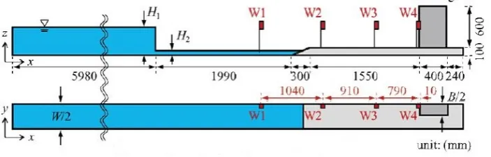
An experiment conducted by Ikeno et al. (2003), is taken for validating the CEL technique. Ikeno et al. (2003), conducted a 2-D experimental study for estimating tsunami wave pressure without soliton fission. Figure 4 shows the domain for experimental study and the instrumented locations. Wave was generated using dam break scenario with offshore depth of height H1= 40 cm and near shore depth of height H2 = 5cm. The dimensions of the structure are width of the structure: B= 10cm, height of the structure: H= 60cm, width of the channel: W= 10cm.
In the experiment, four wave gauges (W1, W2, W3 and W4) were used to measure the wave height at different locations. The measured wave heights are compared with the results of the simulated model in ABAQUS. In this simulation the structure is rigid and expected to produce good insights about flood routing capabilities of CEL.
CEL technique requires to model fluid using Eulerian element, while the structure and ground to be modelled using Lagrangian element. In Figure 5, (blue part) represents the fluid domain (Eulerian) as well as Lagrangian element of the model. The Eulerian part, i.e. wherever water can flow, is partitioned in order to provide a region for the initial location of the water material. All other partitions are assigned the void material option during the material assignment step. Water is used for material assignment in Eulerian domain. The material is an Equation of State model, with no viscosity. This material model represents an inviscid Euler fluid. Because the flow in this problem is essentially incompressible, the modelled speed of sound must only be sufficiently large relative to the flow velocities in order to accurately approximate the governing equations.
Shell rigid elements with based fixity are used to define the Lagrangian domain as routing of water is the objective. General contact is used to define the contact between Eulerian mesh and Lagrangian domain. While the general contact capability of ABAQUS explicit allows the all-inclusive general contact definition, it helps to eliminate unnecessary contact surfaces from the CEL analysis to improve the efficiency. Gravity is applied throughout the domain and disturbance is generated using dam break scenario.
Figure 5. Eulerian and Lagrangian domain at time = 0sec
Validation Results
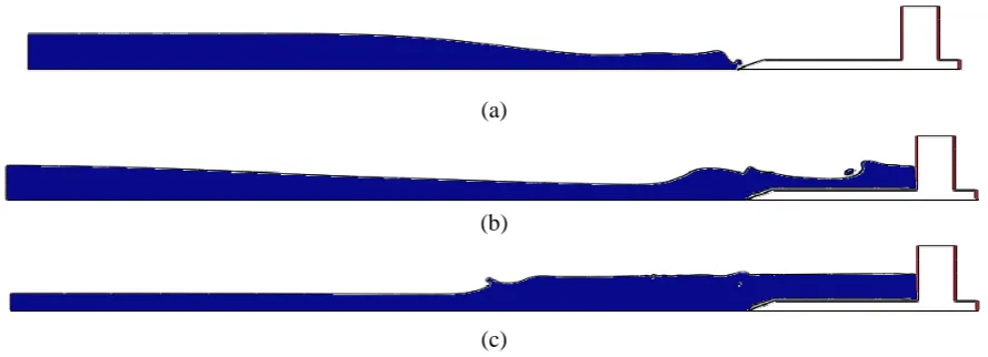
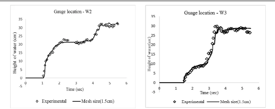
Figure 6 shows the simulated variation of water level at different time. CEL results of water heights at two different gauge locations (W2 and W3) with respect to time are compared with experimental results, Figure 7. It can be inferred from Figure 7 that the CEL having the capability of simulating flood routing. Mesh independency is also carried out considering mesh sizes of 3cm, 2cm and 1.5cm.
(a)
(b)
(c)
Figure 7: Comparison of CEL results with experimental values at gauge locations W2 and W3
FLOOD PROPAGATION INSIDE A PLANT BUILDING
Problem definition
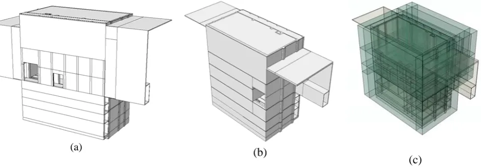
A typical building configuration of an Indian coastal NPP is considered to study the routing of flood water generated due to tsunami. This safety related building/structure have two major openings/penetrations in outer wall (facing the coast line) and can be seen in figure 7(a). The larger one is material handling door. The structure consists of two basements and three upper stories including ground floor level. Ground floor slab as well as one basement slabs at different elevations also have several openings through which each floor is communicated. Largest opening (door) of the Front wall (coast face) is connected to adjacent inner safety related structure and generally used for material handling. Another door in the front wall is connected to this safety related building directly through a common peripheral corridor. Safety related equipment is installed at basements. Inner building, connected with large door passage from front wall, housed critical equipment and doors will be opened mainly during equipment loading or unloading operations.
It is generally assumed that if the floor gets flooded or maximum water level at any location exceeds a particular value, floors below this levels including equipment present on lower floors are unavailable. This may not be true always as flooding of different floors depends on routing of flood water inside the building, which is main objective of this study. A realistic flood routing simulation will give an idea about flooding of a particular floor, time taken to flood the floor. This will help in planning the emergency measures during tsunami warning/Tsunami flooding and input for PSA studies, in view of availability of safety equipment during flood.
Numerical Model of Eulerian Domain
Entire building is covered with Eulerain domain considering initial position of water is near the outer wall. The behaviour of liquids such as water is modelled using Mie–Gruneisen equation of state (EOS) model with linear Us–Up Hugoniot form. The properties of water is tabulated in Table 1.
Table 1: Properties of water in CEL model
c0 (Reference sound speed) s (slope of Us–Up curve) Gruneisen ratio) 0 (viscocity)
The material/water in Eulerian cell elements will be occupied based on volume fraction (V/F) ratio, where V/F=1.0 means fully occupied and 0 means empty (void). Initially water is occupied volume/cells in front of the wall considering V/F=1.0 for a height of 6m. This height is the peak tsunami water height near the plant building after inundation. In Figure 7(a), blue colour portion represents the initial water position of the Eulerian domain and the grey colour portion represent building at onset of simulation, i.e. time t=0 sec.
Numerical Model of Lagrangian Domain
In this study, the structure/plant building is modelled as rigid (non-deformable) in FE simulation. Because main objective of this study is to assess the flood routing. Therefore, structure of the plant building will act as obstruction or non-flow domain.
Finite Element Technique
A horizontal velocity of 6 m/s is applied to the water volume, which is the peak velocity output from MIKE analysis for inundation. Gravity is also applied throughout the domain to allow water to flow to the basement due to gravitational force along with horizontal force. General contact algorithm is used for interacting water with structure, where interaction will happen only when V/F is more than 0.5. Simulation is done using ABAQUS/Explicit (2014) technique considering CEL methodology for this fluid structure interaction study. Continuous ‘inflow’ with same velocity is applied to rear face of water volume. The simulation is done for 300 sec or 5 min as peak flow duration is 5min based on results from MIKE analysis. Figure 7 shows the front view (sea facing), side view of plant building and structure with Eularian domain.
(a)
(b)
(c)
Figure 7. (a) and (b) Front and side view of plant structure and (c) structure with Eularian domain
Results of Simulation
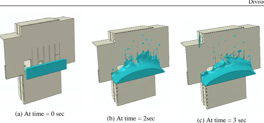
(a) At time = 0 sec
(b) At time = 2sec (c) At time = 3 sec
Figure 8. Flood water entry at different interval at entry of the building
Within 3 sec water enters to the ground floor through smaller door entry, Figure 9(a). Water enters to adjacent safety building through material transfer door (larger door) simultaneously, Figure 9(c). Figure (b) shows water starts flooding the ground floor within 5 sec.
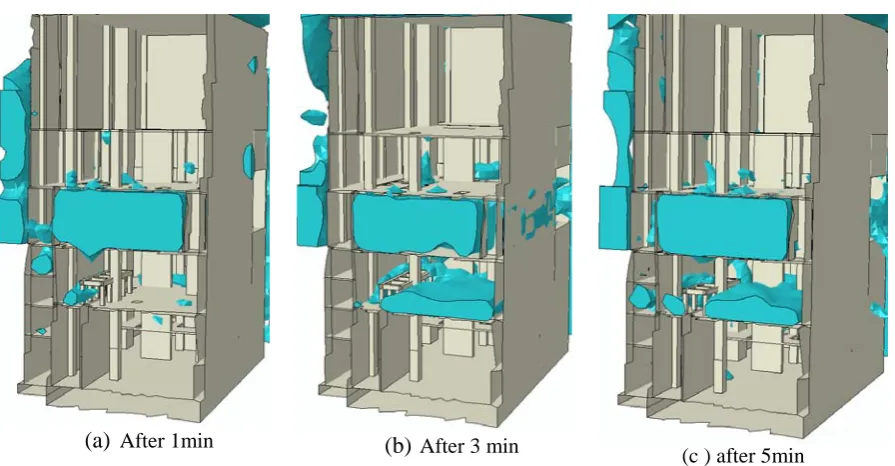
Chronological flooding of basements are shown in Figure 10. Simulation shows that it takes 1 min to fully flood the ground floor, Figure 10(a). Subsequently, water starts flowing to 1st basement, Figure 10(b). Water does not reach the 2nd or lowest basement even after 5min, Figure 10(c) (maximum duration of peak height of water obtained from MIKE output).
Simulation shows that immediate floor of entry is flooded once tsunami water reaches near the plant structure. Subsequently, basements are flooded and lastly lower most basement are flooded. Before simulation it is assumed that water will reach to lowest basement immediately after entering to the building as there are co-linear openings in ground floor and basements. But the flood routing simulation shows that flood water jumps over the floor opening because of high velocity and floods/fill the immediate floor and subsequently reaches to lower floor. Therefore, it takes larger time to flood the lowest basement.
(a) At time =3 sec (b) At time =5 sec (c) At time = 3 sec
(a) After 1min (b) After 3 min
(c ) after 5min
Figure 10. Cross-sectional view of the flow ingress in the building
CONCLUSION
Safety of coastal NPP against external flood is utmost challenge that too flood due to tsunami, like Fukushima. AERB taken up an exercise of external flood PSA. Initially various synthetic scaled up tsunamis are generated and these tsunamis are allowed to propagate to near coast. Considering wave height time history of tsunami at near shore, inundation study is conducted using MIKE software. In this study, various plant buildings are simulated to assess the flooding, i.e. arrival of inundated water, water depth/height and velocity. Considering this input, flood water routing is simulated inside the plant building.
Initially, it is expected that lowest basement will be flooded immediately once water enters the building as there are large openings on floors. Simulation shows that water floods the immediate floor and subsequently, basements are flooded. From simulation it is seen that flood water jumps over the floor opening because of high velocity and floods the immediate floor. Therefore, there is considerable time to flood the lowest basement. This is an important finding of this study.
Flood routing study also shows that water enters to the adjacent building through material transport door almost immediately once water strikes the front wall. Therefore, it is advisable to close the door of material transport and no material handling should be allowed in case of tsunami warning. All the coast facing doors, those are probable entry of flood water, should be replaced with water leak-tight door and sufficiently strong enough to withstand tsunami water impact loading.
REFERENCES
Abaqus-6.10, 2010. Abaqus 6.10 User Documentation – User Manual. Dassult Systems Simulia Crop, Providence, RI, USA.
A. D. Roshan, P. C. Basu (2016). “Tsunami hazard assessmnet of Indian coast”. Natural Hazards. 82, 733.
Ikeno, M. and H. Tanaka. (2003). “Experimental study on impulse force of drift body and tsunami running up to land”, Proceedings of Coastal Engineering, JSCE, 50, 721-725
JNES (2008) Japan Nuclear Energy Safety Organization (JNES), Tsunami Simulation Code ‘‘TSUNAMI’’ Manual, Japan Nuclear Energy Safety Organization (JNES)