Modeling and Analysis of V6 Engine Mount
Bracket
P.Lakshmi Kala
1, V.Ratna Kiran
2P.G. Scholar, Department of Mechanical Engineering, VNR Vignana Jyothi Institute of Engineering and Technology,
Hyderabad, Telangana, India1
Assistant Professor, Department of Mechanical Engineering, VNR Vignana Jyothi Institute of Engineering and
Technology, Hyderabad, Telangana, India2
ABSTRACT: Engine is one of the most important components of a road vehicle such as bus. High performance vehicles has their engine supported by bracket. The engine mounting plays an important role in reducing the noise and vibrations, improving the comfort and work environment of a bus. Engine mounting bracket has been designed as a framework to support engine. The first and foremost function of engine mounting bracket is to properly balance the power pack (engine and transmission) on the vehicle chassis for good motion control as well as good isolation. Present work deals with FE analysis of engine mounting bracket. It includes the modeling of engine mount bracket using CAD software. FE analysis of a typical engine mount bracket of a bus will be carried out and natural frequency will be determined.
KEYWORDS: Engine mounting bracket, Modeling, Modal analysis, Frequency.
I. INTRODUCTION
The main objectives of his paper are modelling in CAD software and modal analysis of the engine mount bracket to find the natural frequency.
II.BRIEF OVERVIEW OF LITERATURE
A. Prasad Babu et al. [1], presented the topology optimization approach to create an innovative design of an engine mount bracket using Altair Opti-struct software. Materials selected were aluminium alloy, aluminium silicon carbide and grey cast iron. The structural analysis of the basic model has done by using Radioss tool and weight reduction through the usage of Altair Opti-struct software. The results obtained from the structural and modal analysis have shown that the weight is reduced by 54% through the usage of optimized aluminium silicon carbide MMC composite material.
V. Ratna Kiran [2], optimized the weight of V6 engine mount bracket by varying the rib thickness. Material selected is aluminium alloy. The bracket is modelled by 6mm, 7mm and 8mm rib thickness. Analysis of engine mount bracket is done and the results obtained from static structural and modal analysis have shown that the model with 7mm rib thickness is best suitable. The weight of the component is optimized up to 50-60% with 7mm rib thickness.
Umesh S.Ghorpade et al. [3],proposed the analytical method to determine the non-linear vibrations for Magnesium, Aluminum &GCI and to reduce the excessive computation time. In this paper 3D model of non-linear materials is analyzed. Some simplification with an appropriate idealization process including changing material and reduced mesh size in the FE model is done. Meshing of different material mount brackets is done at the mid-surface using Hex Dominant Quadrilateral and Triangular elements. By this experimental process and comparisons it is concluded that Magnesium alloy is best suitable and exhibits better damping characteristics than Aluminum alloy
Sahil Naghate et al.[4], used finite element analysis tool to analyze the engine mounting bracket using FEA Package. Materials selected were aluminium alloy and magnesium alloy. The results obtained from the static and dynamic analysis have shown that the magnesium is better than aluminium. The main advantage of the magnesium engine mounting bracket was its light weight, which can increase fuel efficiency. The main problem of using magnesium instead of aluminium was its higher cost. Thus, it can be concluded that magnesium and aluminium both preferred as a material for an engine mounting bracket.
Mr. Pramod Walunje et al.[5], proposed the algorithm known as Fast Fourier Transform (FFT) to find the natural frequency for different material mount brackets and compared with the Ansys software. Materials considered were grey cast iron, aluminium and magnesium. The results obtained from static structural and modal analysis have shown that aluminium alloy is best suitable for engine mount bracket and has mass of 0.55kg. Further the weight optimization has done by reducing the thickness of 2mm. Thus, it can be concluded that by using light weight material aluminium weight has been reduced up to 0.43kg.
III. LOCATION OF BRACKET INSTALLATION
Fig.2 (a)
Fig.2 (b)
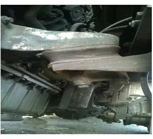
Fig. 2(a), 2(b). Location of Engine Mount Bracket
temperature, and corrosion as the essential product, requirements), and are not to decrease the mount performance thus meet first mode resonance and stiffness requirements.
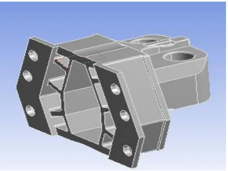
Fig.1. Engine Mount Bracket
Figure 1 shows the shape of engine mount bracket of a V6 engine.The retaining bracket is mounted on the vehicle body. In such an automobile engine supporting structure, a cut-out portion is formed at either a bolt insertion-hole of the supporting bracket or a bolt insertion-hole of the retaining bracket for permitting the engine to be turned on an axis extending in a transverse direction of the vehicle in proportion with impact loads. The impact loads are imposed on the engine upon a collision of the vehicle. As a result, the engine is prevented from horizontal movement in a rearward direction of the vehicle upon a frontal collision of the automobile.
IV. PROPOSED METHODOLOGY
At first the theoretical study of bracket is done. The overall purpose of engine mounting bracket is to support the engine and sustain the vibrations caused by engine as well as bumps from tires due to uneven road surfaces.
The analysis for the engine mount bracket will be done as follows:
1. CAD model was generated with the help of reverse engineering (i.e.,) through manual measuring instruments of engine mounting bracket (physical part).
2. Pre-processing in a CAE software
Discretization and meshing of the geometry.
Application of the boundary conditions (taken from standard testing conditions in the automotive industry).
3. Solution for normal modes and frequency response analysis.
V.OBJECTIVE
VI. MODELING OF ENGINE MOUNT BRACKET
The base model is designed in Creo software for creation of 3d model, and then it is converted to the intermediate file
formats such as STEP, IGES which are essential for importing in to the other meshing software.
A. Reverse engineering
As computer-aided design (CAD) has become more popular, reverse engineering has become a viable method to create a 3D virtual model of an existing physical part for use in 3D CAD, CAM, CAE or other software. The reverse-engineering process involves measuring an object and then reconstructing it as a 3D model.The physical object can be measured by using 3D scanning and manual measuring.
Reverse engineering of the engine mounting bracket, shown in Fig. 1, is done by using manual measuring devices. CREO is a powerful software used to create complex designs with great precision. The design intent of any three-dimensional (3D) model or an assembly is defined by its specification and its use. The parametric nature of this software helps preserve the design intent of a model with tremendous ease.
B. Steps in Modeling of Engine Mount Bracket
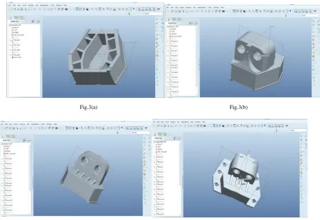
Fig.3(a) Fig.3(b)
Fig.3(c) Fig.3 (d)
The above figures shows the step by step modeling of engine mount bracket in Creo software. The 3D modelled engine bracket is then analyzed.
VII. ANALYSIS OF ENGINE MOUNTING BRACKET
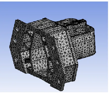
Finite element analysis (FEA) is one of the most popular engineering analysis methods for Non-linear problems. Aluminum alloy material is selected from the engineering data sheet of the FEA package software. FEA requires a finite element mesh as a geometric input. This mesh can be generated directly from a solid model for the detailed part model designed in a three-dimensional (3D) CAD system. The importance of the meshing in the whole process of analysis is very important from the point of result implementation. By size and shape of the meshing accurate results can carry out.
Aluminum alloy under consideration has the following material properties:
Young’s modulus – 7.1e+10 N/m2,
Poisson’s ratio – 0.33,
Density – 2770 Kg/m3,
Yield strength in tension & compression – 2.8e+8 N/m2.
A. Modal analysis
The modal analysis of the engine mounting bracket is carried out for determining natural frequencies and shapes of the natural vibration modes. These frequencies are the outputs given by the analysis of the engine mounting bracket. The frequency range of engine is 0-1500 Hz.
Fig.4. Meshed Model
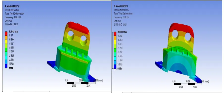
Fig.5. First mode of vibrationFig.6. Second mode of vibration
Figure 5 and figure 6 shows the natural frequency with first mode and second mode of vibrations. From the above plot of the total deformation of the engine mounting bracket we can conclude that maximum value of deformation is taking place at the place that is connected to the engine. The frequency of vibration is 1181.5 Hz. The values of deformation increasing from minimum to maximum from the bottom which is connected to the vehicle structure to the end of engine.
VIII. RESULT AND CONCLUSION
From the modal analysis results of Engine Mounting Bracket of V6 engine made of Aluminum alloy has the natural frequency of 1181.5 Hz. Thus, the use of CAE tools leads to an easy visualization and thereby helping in the detection of problems early in the design cycle, reduced number of physical prototypes resulting in significant saving of time and cost and last but not the least, more design iterations by incorporating simulation techniques.
Future Scope
The proposed analysis procedure will be used to study the effects of different materials and features like ribs
in the bracket for improvements like increasing the natural frequency and lowering the stress levels.
Mass optimization of the mounting bracket and cost reduction of the material.
ACKNOWLEDGEMENT
We would like to thank the Volvo bus servicing centre management and management of VNR Vignana Jyothi Institute of Engineering and Technology, Hyderabad for their consistent support in execution of this work.
RERERENCES
[1] Prasad Babu, Y.Vijaya Kumar and Dr.C.Udaya Kiran, “Topology optimization in design of engine mounting bracket”, International Conference on Emerging Trends in Mechanical Engineering, Vol. 1, 2014.
[2] V. Ratna Kiran, “Design optimization for engine mount bracket for V6 engine”, Proceedings of 2nd International Conference on Advances in Mechanical and Building Sciences, V.I.T.U., India, pp. no 814-819.
[5] Mr. Pramod Walunje and Prof. V.K.Kurkute, Optimization of Engine Mounting Bracket Using FEA, PARIPEX-Indian Journal of Research, Vol. 2,2013.
[6] Yunhe Yu, Nagi G.Naganathan, and Rao V.Dukkipat, A Literature review of automotive vehicle engine mounting systems, PERGAMON-Elsevier, Mechanism and Machine Theory, 2001, pp.123-142.
BIOGRAPHY
Ms P.Lakshmi Kala received her B.Tech in Mechanical Engineering from PRRM Engineering College, India, in 2013. She is currently an M.Tech student at VNRVJIET, Hyderabad, India. Her research interests include CAD/CAM, Modeling and Finite Element Analysis (FEA).