Effect of Load Distribution on Dynamic
Response of Double Layer Grids Space Steel
Frames
Dr. Ihab Sabri 1, Zeinab Abdulzahra 2
Lecturer, Department of Civil Engineering, Basrah Engineering College, Basrah, Iraq1 M.Sc. Student, Department of Civil Engineering, Basrah Engineering College, Basrah, Iraq2
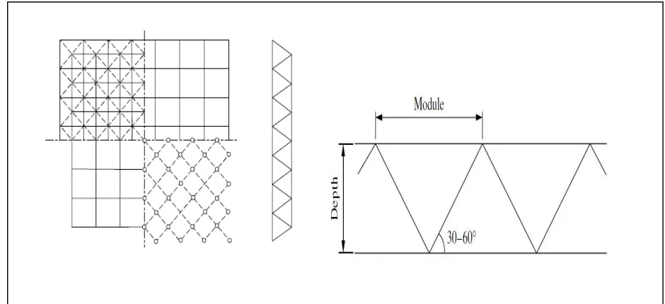
ABSTRACT: Double layer grids is a space frame consisting of two planar networks of members forming the top and bottom-layers parallel to each other and interconnected by vertical and inclined members. There are many types of pace frames. The most popular is orthogonal square pyramid space grids shown in Fig.(1-1). Space frames are rigid, light weight, flexible and a valuable tool for engineers in the search for new forms of construction. This paper represent the response of space steel double layers frames with different positioning of point loads using Time History Analysis. Two different models, one with modular angle 45°and the other with modular angle of 30 Which is subjected to dynamic wave load is studied. This study also incorporate how the maximum displacement reduced by the change of loading condition.
KEYWORDS: Double layer grids, Space steel frame, Orthogonal square pyramid space grids, Modular angle, Dynamic analysis, Load distribution.
I. INTRODUCTION
The definition of space frame can quoted from working group on spatial steel structure of International Association on Shell and Spatial structure in 1984 : "Space frame is structural system assembled of linear elements, so arranged that the forces are transferred in a three dimensional manner". In some, the constituent element may be two dimensional. Macroscopically a space frame often takes the form of flat or curved surface [1]. Space frames provided what engineers and architects looking for, because they are Long span structure with few or no internal supports, light weight, economical, high speed construction structure and aesthetically pleasing. The advantages of space frame are[2]: light, elegant and economical means of covering large column free spaces, three dimensional action, small deflection, save construction time and assembled and erected by unskilled labour. The space frame type depends mainly on the type of connection used and on range of geometries associated with the space frame system. Choosing the type of double layer grids depends on the shape of the building plan, size of span, supporting conditions, magnitude of loading, roof construction and architectural requirement [4] There are two type of space frames according to the geometry properties : latticed shell and double layer grids.
Double layer grids is a space frame consisting of two planner networks of members forming the top and bottom layers parallel to each other and interconnected by vertical and inclined members. Double layer grids are characterized by hinged joints. All members can only resist tension or compression. Orthogonal square pyramid space grids is the most commonly used frame patterns with top layer square grids offset over bottom layer grids and the top and bottom chord members have equal length.
The collapse patterns of double layer grids was investigated by Madi and EL-Tayem [5]. Square on square, square on diagonal, diagonal on square and diagonal on diagonal were used with varying side dimensions, depth, module, supports and number of member types and their response to vertical loading was traced to collapse. It was observed that double layer grid have a similar failure patterns of the flat concrete slab and factors affect the patterns were the number of the supports, the grid depth and relative strength of the member while the grid module or configuration have no or little effect and increasing the number of support increase the economy of the double layer grid. While, the effect of horizontal seismic action on the double layer space grid was studied by A.S. Karamanos and S.A. Karamanos[6]. It was found that grid frameworks are parts of larger structural systems and their seismic response depend on their interaction with the substructure, the double layer grid design must primarily ensure the seismic energy dissipation through the formation of dissipative zone, and the hysteretic response can be improved by using tubular members.
Figure (1-1) : Double layers grid space frame
II. MATERIALANDMETHODS
For the analysis a double layer grids space frame of type square on square space grid under dynamic load. After choosing the type of model, the depth and module size were determined.
A finite element analysis package SAP2000 V.15.01 Ultimate was used to carry out the linear dynamic analysis. The member of the space frame is consisted of standard round shape section cold folded steel. One element per member was considered in this study.
The model members defined as a steel frame under the specification of ASTM (American Society of Testing and Material) A500 Grade B, Fy42 (HSS round) for cold folded steel. Frame sections used in the model was a round pipe of a 3 inch diameter.
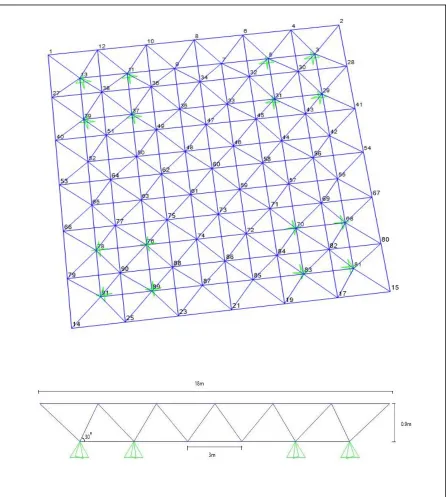
Two models were used, model one is double layers grid space frame type orthogonal square pyramid space grids as shown in Fig. (1-2). It has a dimension of 18×18m , module angle of 30˚ , module length of 3m and 0.9m total depth.
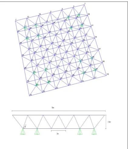
The second model is a double layers grid space frame type orthogonal square pyramid space grids shown in Fig.(1-3), same as the first model with changes in module angle and depth. Model dimension is 18 × 18 m, module angle of 45˚, module length of 3 m and the total depth is 1.5 m.
III.ANALYSISOFRESULTS
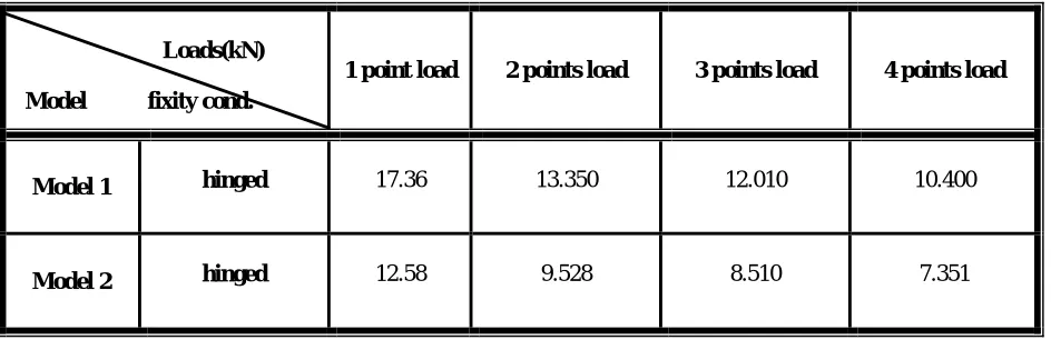
After applying the dynamic load , the maximum displacement is obtained from the time history diagram as shown in Table (1-1).
Table (1-1) The maximum displacement (mm) at maximum loading for different loading condition
Loads(kN)
Model fixity cond.
1 point load 2 points load 3 points load 4 points load
Model 1 hinged 17.36 13.350 12.010 10.400
Model 2 hinged 12.58 9.528 8.510 7.351
Model one, it can be noticed that the maximum displacement reduced by 23.09%, 30.8% and 40%, when the wave force was applied at two, three and four nodes respectively as shown in Table (1-2).
The maximum displacement of model two shown also in Table(1-2). It’s clear that maximum displacements reduced by 24.2%, 32.3% and 41.5%, when the wave force was applied at two, three and four nodes respectively. Also, it can be seen that the reduction in maximum displacement for model two is 1% higher than the reduction percentage of model one because of the module angle changes from 30˚ to 45˚.That’s mean the module angle 45˚is the best module angle in distribution of internal forces in the space frame members.
The reason of these reductions in the maximum displacement was due to the space frame characteristic of distributing the load in three dimensions. From the results it can be indicated that the change of joints connection type have almost no effect on reduction percentage of maximum displacement. Also, it’s clear that the module angle has a notable effect on the reduction percentage of maximum displacements.
Table (1-2) The redaction percentage (%) of maximum displacement at different loading condition
Loads(kN)
Model fixity cond.
1 point load 2 points load 3 points load 4 points load
Model 1 hinged 0 23.099 30.817 40.092
Model 2 hinged 0 24.260 32.352 41.565
Figure (1-4): Vertical displacement under different loading condition for node 60 of model 1
From the figure it can be noticed that for node 60, The highest value of vertical displacement was observed when the total load applied at one node. Other loading conditions show decreasing in the values of vertical displacements because of load distribution on the structural element.
Figure (1-5): Vertical displacement under different loading condition for node 58 of model 1
For node 58, The highest value of vertical displacement was registered in the second loading conditions. This is because one of these loads was applied directly on node 58. In the other loading conditions, the values of vertical displacements were decreased because of load distribution and the decreasing the value of load which applied directly on this node.
-20 -15 -10 -5 0 5 10 15 20
0 50 100 150 200 250
D is p la ce m en t U Z (m m ) Time (sec) Joint 60
1 point load
2 point loads
3 point loads
4 point loads
-15 -10 -5 0 5 10 15
0 50 100 150 200 250
D is p la ce m e n t U Z (m m ) Time (sec) Joint 58
1 point load
2 point loads
3 point loads
Figure (1-6): Vertical displacement under different loading condition for node 73 of model 1
The maximum value of displacements for node 73 was observed under the third loading condition (Total load divided on three and applied on three nodes). This is because one of these loads applied directly applied on this node. The values of the vertical displacement under the first load conditions were similar to those values of vertical displacement under third loading conditions. Similar behaviour between node 73 and node 58 were observed.
Figure (1-7): Vertical displacement under different loading condition for node 71 of model 1
While for node 71, The value of maximum displacement was registered in the fourth loading condition (Total load divided on four and applied on four nodes). This is because one of these loads was applied directly on this node. The first loading condition gave the lowest values of vertical displacements. This is due to the three dimensions load distribution characteristic of space frame.
-15 -10 -5 0 5 10
0 50 100 150 200 250
D is p la ce m e n t U Z (m m ) Time (sec) Joint 73
1 point load
2 point loads
3 point loads
4 point loads
-8 -6 -4 -2 0 2 4 6 8
0 50 100 150 200 250
D is p la ce m e n t U Z (m m ) Time (sec) Joint 71
1 point load
2 point loads
3 point loads
Figure (1-8): Vertical displacement under different loading condition for node 54 of model 1
An alternative response was observed at node 54,upward displacements were observed at the beginning time of loading because of this node located after the supports in the extreme line of space frame. The highest value of vertical displacement was observed when the total load applied at one node. Other loading conditions show decreasing in the values of vertical displacements because of load distribution on the structural element.
It can be noticed that nodes of model two have the same behaviour of model one but with lowest value of maximum displacement.
Figure (1-9): Vertical displacement under different loading condition for node 60 of model 2
The highest value of vertical displacement under different loading conditions on node 60 was perceive when the total load applied at one node. The values of vertical displacements in other loading conditions decreased because of load distribution on the structural element.
-4 -3 -2 -1 0 1 2 3
0 50 100 150 200 250
D is p la ce m en t U Z (m m ) Time (sec) Joint 54
1 point load
2 point loads
3 point loads
4 point loads
-15 -10 -5 0 5 10 15
0 50 100 150 200 250 300
D is p la ce m e n t U Z (m m ) Time (sec) Joint 60
1 point load
2 point loads
3 point loads
Figure (1-10):Vertical displacement under different loading condition for node 58 of model 2
The highest value of vertical displacement of node 58 was registered in the second loading conditions (Total load divided on two and applied on two nodes). This is because one of these loads was applied directly on node 58. In the other loading conditions, the values of vertical displacements were decreased because of load distribution and the decreasing the value of load which applied directly on this node.
Figure (1-11):Vertical displacement under different loading condition for node 73 of model 2
The maximum value of displacements of node 73 was observed under the third loading condition (Total load divided on three and applied on three nodes). This is because one of these loads applied directly applied on this node. The values of the vertical displacement under the first load conditions were similar to those values of vertical displacement under third loading conditions. Similar behaviour between node 73 and node 58 were observed.
-10 -5 0 5 10
0 50 100 150 200 250 300
D is p la ce m e n t U Z (m m ) Time (sec) Joint 58
1 point load
2 point loads
3 point loads
4 piont loads
-8 -6 -4 -2 0 2 4 6 8
0 50 100 150 200 250 300
D is p la ce m e n t U Z (m m ) Time (sec) Joint 73
1 point load
2 point loads
3 point loads
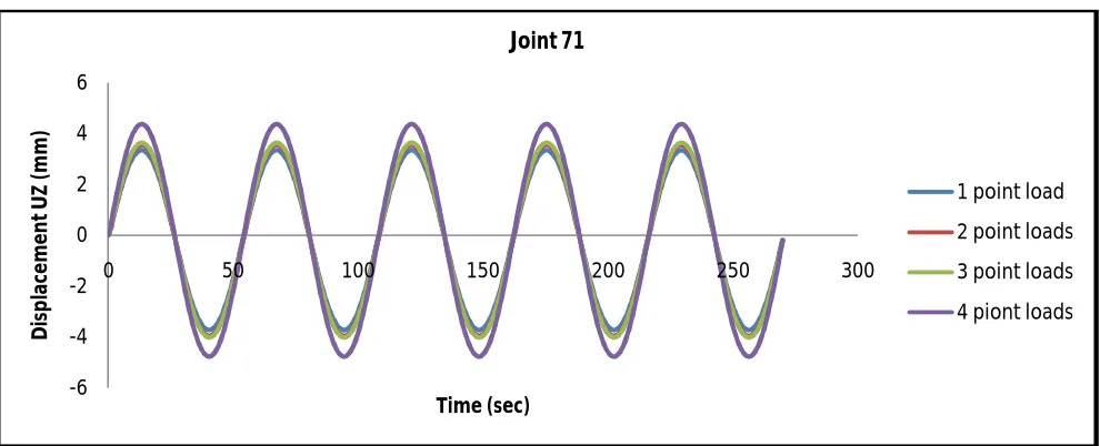
Figure (1-12):Vertical displacement under different loading condition for node 71 of model 2
The value of maximum displacement of node 71 was registered in the fourth loading condition (Total load divided on four and applied on four nodes). This is because one of these loads was applied directly on this node. The first loading condition gave the lowest values of vertical displacements. This is due to the three dimensions load distribution characteristic of space frame
Figure (1-13):Vertical displacement under different loading condition for node 54 of model 2
An alternative response was observed at this node, upward displacements were observed at the beginning time of loading because of this node located after the supports in the extreme line of space frame. The highest value of vertical displacement was observed when the total load applied at one node. Other loading conditions show decreasing in the values of vertical displacements because of load distribution on the structural element
-6 -4 -2 0 2 4 6
0 50 100 150 200 250 300
D is p la ce m e n t U Z (m m ) Time (sec) Joint 71
1 point load
2 point loads
3 point loads
4 piont loads
-2.5 -2 -1.5 -1 -0.5 0 0.5 1 1.5 2
0 50 100 150 200 250 300
D is p la ce m e n t U Z (m m ) Time (sec) Joint 54
1 point load
2 point loads
3 point loads
IV. CONCLUSION
This paper represent a numerical study on double layers space steel frames under dynamic wave load. This type of space frame is very popular in many countries but it is behaviour has not completely understood. The main concluding that have been achieved from the finite element analysis may be summarized as follows
1. The best modular angle in double layers grid space frame is 45˚.This angle gives lowest value of maximum displacement.
2. Space frame of type orthogonal square pyramid space grids with modular angle 45˚ gives the highest value of reduction factor in maximum displacement at different loading condition.
3.Space frame of type orthogonal square pyramid space grids with modular angle 45˚ gives larger values of reduction factor in maximum displacement at different loading condition.
4. Loading conditions have a big effect on the nodes which is under or near to the loading location, While this effect decrease in the nodes which is far from the loading location, specially the nodes which located near to the supports.
REFERENCES
[1] IASS(International Association for Shell and Spatial Structure) Working Group on Spatial Steel Structures, "Analysis, design and realization of space frame", IASS No.84/85, XXV(1/2), pp.1-114, 1984.
[2] Ramaswamy, G.S., Eekhout, M. and Suresh, G.R., "Analysis, Design and Construction of Steel Space Frames", Thomas Telford, ISBN 0727730142, 2002.
[3] Lan, T.T, Hand Book of Structural Engineering, CRC Press, second edition, ISBN 0849315697, 2005.
[4] Razwan, S.A. and Bhatti, A.A. , ''On the performance of double layer square on square grids'', Space structure 4th , International conference space structures 4, V. 1, pp. 614-621, 1993.
[5] Madi, U.R. and El-Tayem, A., ''Collapse patterns for double layer grids'', Space structure 4th , International conference space structures 4, V. 1, pp. 631-639, 1993.