SRINIVASARAO, KOUNDINYA B. Traffic Grooming in Translucent Optical Ring
Net-works. (Under the direction of Dr. Rudra Dutta).
The exponential growth of the Internet has resulted in an ever increasing
de-mand for bandwidth. Carrier networks which form the backbone of the Internet, have
been designed to carry only voice signals with predictable traffic patterns and anticipating
slow growth of the network. With the advances in fiber optics and wavelength division
multiplexing (WDM) optical networking is the key to satisfy the data-driven bandwidth
demand. These technologies enable simultaneous transmission of signals on separate
high-speed channels at different wavelengths. While the bandwidth provided by these channels
is very high, individual traffic demands are at the sub-wavelength level. This mismatch can
be overcome by multiplexing several lower rate connections onto the high-speed channels in
a cost-effective manner. This technique is referred to as traffic grooming. Traffic grooming
in WDM networks has been a widely addressed problem in recent years. Traffic grooming
and its constituent subproblems have been proven to be NP-complete for even the most
elemental of network topologies. The ring topology has been the target of a large number
of the studies because of its practical relevance. However, most existing studies concentrate
on some objective function that is aggregated over all the network nodes, such as the total
number of ADMs used or the total amount of opto-electro-optical (OEO) routing performed.
From a practical point of view, it is likely that every network node would be provisioned
similarly. Hence a min-max objective, seeking to minimize the OEO equipment needed at
the node which needs the maximum of such equipment is more appropriate. Such objectives
are usually harder to optimize than aggregate objectives which are themselves known to be
computationally intractable. In this thesis, we study traffic grooming in a unidirectional
ring network under different traffic patterns for the min-max objective. We define two
heuristic approaches based on decomposition; one is based on grouping the nodes, and the
other on partitioning the traffic matrix. We show that the second approach is more general,
but is costlier in terms of computation; further, we indicate traffic families for which the
first approach may be expected to perform nearly as well as the more complex one. We also
investigate several variations of these two main approaches. We present numerical results
by
Koundinya B Srinivasarao
A dissertation submitted to the Graduate Faculty of North Carolina State University
in partial satisfaction of the requirements for the Degree of
Master of Science
Department of Computer Science
Raleigh
2003
Approved By:
Dr. Peng Ning Dr. George N. Rouskas
To my parents,
B V Srinivasa Rao, Shakunthala S Rao
and my sister,
Biography
Koundinya Srinivasarao was born in Mysore, India, in 1977. He received his Bachelor’s
degree in Computer Science and Engineering from R V College of Engineering, Bangalore,
India in 1999. From 1999 to 2001 he worked for IBM India as a software engineer in various
e-Business projects. At IBM India, he was a member of theTechnology Incubation Center, a
core group that identifies and incubates key emerging technology areas and also participated
in the activities of several special interest groups. Since 2001, he has been a Masters student
Acknowledgements
I acknowledge the efforts of Dr. Rudra Dutta, my thesis advisor, in providing me direction
and guidance when required. He helped me remain focused and persistent. Working with
him has been a pleasure and honor. I am also grateful to him for the financial support he
accorded.
I thank Dr. Rouskas and Dr. Ning for serving on my thesis advisory committee
and providing me with invaluable advice.
I acknowledge the immense help I received from Bensong Chen, one of my
col-leagues at the department. I am grateful to him for having shared his code and research
data.
I thank my family for encouraging me to take up graduate studies. In this endeavor,
they have put in just as much effort as me.
I thank my friends—Bhasker, Naveen, Prashant, Pushkin and Vishwas, for making
Contents
List of Figures viii
List of Abbreviations x
1 Introduction 1
2 Context 4
2.1 Architecture of Optical Networks . . . 4
2.1.1 Introduction . . . 4
2.1.2 Translucent Optical Networks . . . 8
2.2 Virtual Topology Design . . . 10
2.3 Traffic Grooming . . . 11
2.3.1 Grooming Cost Functions . . . 13
2.4 Traffic Grooming Literature Survey . . . 14
2.4.1 General Approaches . . . 14
2.4.2 Decomposition Approaches to Traffic Grooming . . . 15
3 Problem Definition 18 3.1 Traffic Grooming with Min-Max Objective . . . 18
3.2 Assumptions . . . 20
3.2.1 Traffic Pattern Characterization . . . 21
4 Node Grouping 24 4.1 Description and Rationale . . . 24
4.2 Applicability to CD/NCD Traffic Matrices . . . 29
4.2.1 Grouping techniques . . . 37
4.3 Applicability to Source-wise Uniform Traffic . . . 38
4.3.1 Grouping technique . . . 38
4.3.1.1 Constant and Falling Strictly Source-wise Uniform Traffic Matrices . . . 38
4.3.1.2 Rising Strictly Source-wise Uniform Traffic Matrices . . . . 42
4.4 Time Complexity Analysis . . . 45
5 Decomposition through Traffic Matrix Slicing 46 5.1 Rationale . . . 46
5.2 Grooming the Sliced Traffic Matrix . . . 48
5.2.1 Transformation to a Path Grooming Problem . . . 48
5.2.2 Path Grooming Algorithms . . . 49
5.3 Traffic Matrix Slicing . . . 50
5.3.1 Placement of Quasi-opaque Nodes . . . 51
5.3.2 Uniform and Non-uniform Slicing . . . 52
5.4 Time Complexity Analysis . . . 53
5.5 Traffic matrix slicing of node-grouped traffic matrices . . . 54
6 Numerical Results 55 6.1 Traffic Matrix Generation . . . 56
6.2 Node Grouping . . . 57
6.2.1 Localized Traffic . . . 57
6.2.1.1 CD Traffic . . . 57
6.2.1.2 NCD Traffic . . . 63
6.2.2 Source-wise Uniform Traffic . . . 63
6.2.3 Discussion . . . 67
6.3 Traffic Matrix Slicing . . . 70
6.3.1 Traffic Slicing . . . 70
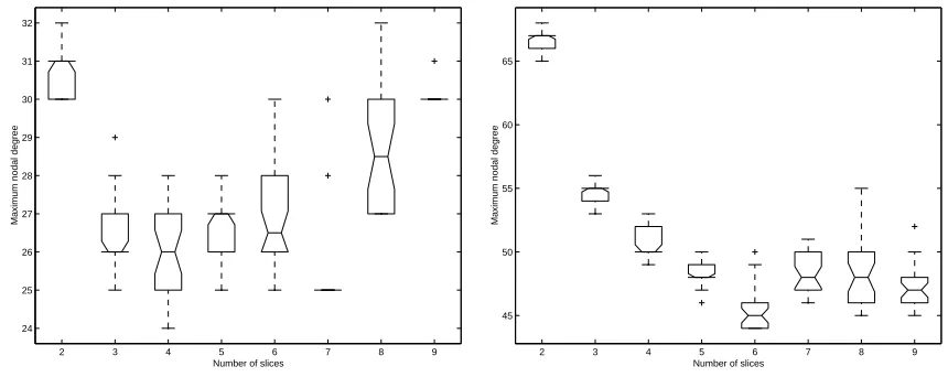
6.3.2 Effect of Number of Slices . . . 71
6.3.3 Placement of Quasi-opaque Nodes . . . 71
6.3.4 Discussion . . . 73
6.4 Relative Performance of Node Grouping and Traffic Matrix Slicing . . . 73
6.4.1 NCD Traffic Matrices . . . 73
6.4.2 Source-wise Uniform Traffic . . . 73
6.4.3 Random Traffic . . . 79
6.4.4 Optimal Solutions for Small Ring Networks . . . 84
6.4.5 Scalability of Node Grouping and Traffic Matrix Slicing . . . 86
6.4.6 Discussion . . . 88
6.5 Traffic Matrix Slicing of Node-grouped Traffic Matrices . . . 90
6.5.1 Recursive Application of Node Grouping to Source-wise Uniform Traffic 90 6.5.2 CD/NCD Traffic Matrices . . . 91
6.5.2.1 CD Traffic . . . 91
6.5.2.2 NCD Traffic . . . 94
6.5.3 Discussion . . . 97
6.6 Summary of Results . . . 97
7 Conclusion and Future Work 99 7.1 Future Work . . . 99
A TPABLO Algorithm 106
List of Figures
2.1 Wavelength Division Multiplexing in a Fiber Link . . . 5
2.2 Wavelength Add/Drop Multiplexer . . . 6
2.3 An all-optical OXC with local add/drop . . . 8
2.4 A typical optical network . . . 9
3.1 An N-node unidirectional ring network . . . 19
4.1 Node grouping example . . . 30
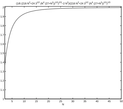
4.2 Maximum Nodal Degree (approximate) for several instances of strictly source-wise uniform falling traffic matrices . . . 41
4.3 Solution for optimal number of interleaved groups . . . 41
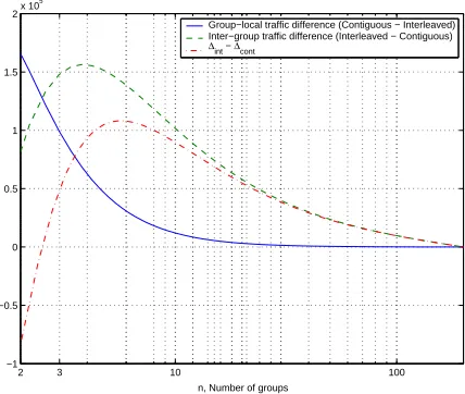
4.4 Difference of group-local and inter-group traffic between interleaved and con-tiguous partitions for strictly source-wise uniform rising traffic and its effect on the maximum nodal degree . . . 44
5.1 Traffic Matrix Slicing Example . . . 47
6.1 Performance of node grouping for low load CD traffic - Set 1 . . . 58
6.2 Performance of node grouping for low load CD traffic - Set 2 . . . 59
6.3 Performance of node grouping for moderate load CD traffic - Set 1 . . . 60
6.4 Performance of node grouping for moderate load CD traffic - Set 2 . . . 61
6.5 Performance of node grouping for high load CD traffic . . . 62
6.6 Performance of node grouping for low load NCD traffic - Set 1 . . . 64
6.7 Performance of node grouping for low load NCD traffic - Set 2 . . . 65
6.8 Performance of node grouping for moderate load NCD traffic - Set 1 . . . . 66
6.9 Performance of node grouping for moderate load NCD traffic - Set 2 . . . . 67
6.10 Performance of node grouping for high load NCD traffic . . . 68
6.11 Interleaved vs Contiguous grouping for statistically source-wise uniform traf-fic with low granularity (C = 16) . . . 69
6.12 Interleaved vs Contiguous grouping for statistically source-wise uniform traf-fic with high granularity (C= 64) . . . 70
6.14 Comparison between performance of node grouping and traffic slicing for low
load NCD traffic . . . 74
6.15 Comparison between performance of node grouping and traffic slicing for low load NCD traffic . . . 75
6.16 Comparison between performance of node grouping and traffic slicing for moderate load NCD traffic . . . 76
6.17 Comparison between performance of node grouping and traffic slicing for moderate load NCD traffic . . . 77
6.18 Comparison between performance of node grouping and traffic slicing for high load NCD traffic . . . 78
6.19 Comparison between performance of node grouping and traffic slicing for moderate load statistically source-wise uniform traffic with low granularity (C= 16) . . . 80
6.20 Comparison between performance of node grouping and traffic slicing for high load statistically source-wise uniform traffic with low granularity (C= 16) . 81 6.21 Comparison between performance of node grouping and traffic slicing for statistically source-wise uniform traffic with high granularity (C = 64) . . . 82
6.22 Comparison between performance of node grouping and traffic slicing for random traffic . . . 83
6.23 Comparison between performance of node grouping and traffic slicing with optimal solution for source-wise uniform constant traffic . . . 85
6.24 Comparison between performance of traffic slicing with optimal solution for source-wise random traffic . . . 86
6.25 Comparison between performance of traffic slicing with optimal solution for 3-hop falling traffic . . . 87
6.26 Scalability of node grouping and traffic slicing with increasing load . . . 89
6.27 Recursive decomposition of statistically source-wise uniform constant traffic 92 6.28 Recursive decomposition of statistically source-wise uniform falling and rising traffic . . . 93
6.29 Recursive decomposition of random traffic . . . 93
6.30 Benefits of slicing node-grouped CD traffic . . . 95
6.31 Benefits of slicing node-grouped NCD traffic . . . 96
List of Abbreviations
CD - Completely Decomposable
ILP - Integer Linear Program
LSP - Label Switched Path
LSR - Label Switching Router
LTE - Line Terminating Equipment
NCD - Nearly Completely Decomposable
OAM - Operations, Administrations and Management
OEO - Opto-electro-optical
OTDM - Optical Time Divivion Multiplexing
OXC - Optical Cross-connect
RWA - Routing and Wavelength Assignment
SDH - Synchronous Digital Hierarchy
SONET - Synchronous Optical Network
TPABLO - Threshold Parameterized Block Ordering
WADM - Wavelength Add/Drop Multiplexor
Chapter 1
Introduction
Telecommunication networks recently have seen a large increase in traffic demands,
especially data traffic as compared to voice traffic. The evolution of optical networking
tech-nologies has resulted in the realization of high bandwidth and high availability networks
not just in the research laboratories but also in commercial environments; see [2] for a list
of optical networking and switching vendors. The main breakthrough was in implementing
opticalwavelength division multiplexing (WDM). WDM is the process of transmitting data
simultaneously at multiple carrier wavelengths over an optical fiber cable keeping the
wave-lengths sufficiently far apart so that they do not interfere with each other. Thus, a single
strand of fiber can be thought of as a collection of high capacity virtual fibers. A single
strand of optical fiber has the potential bandwidth of 50 THz. This bandwidth can be split
across multiple WDM channels with each channel being capable of carrying several Gbps of
data (e.g. Lucent’s offering of 160 wavelengths of 10Gbps capacity [30]). Over the last few
years we have witnessed a wide deployment of point-to-point WDM transmission
technol-ogy in the Internet infrastructure. Today, WDM systems are widely deployed in long-haul
(wide-area) networks. They also have a major presence in the metro-area networks as well.
The corresponding massive increase in bandwidth due to WDM has heightened the need for
faster switching at the core of the network. This coincides with a growing desire to support
different levels of Quality of Service (QoS), which makes it necessary to not only efficiently
utilize the greatly increased available bandwidth, but to manage it with high
are being deployed to address the dual issues of faster switching and QoS support. On
one hand, LSRs simplify the forwarding function, thereby making it possible to operate
at higher data rates. On the other hand, MPLS enables the Internet architecture, built
upon the connectionless Internet Protocol, to behave in a connection-oriented fashion that
is more conducive to QoS and traffic engineering [1].
While current technologies can provide such huge bandwidth, a network would
typically need to support sub-wavelength traffic connections as well. In order to utilize
efficiently the capacity of each lightpath, a number of independent lower-rate traffic streams
must be multiplexed into a single lightpath. These observations give rise to the concept of
traffic grooming, which refers to the techniques used to combine lower speed traffic flows onto available wavelengths in order to meet network design goals such as cost minimization.
With the deployment of commercial WDM systems, it has become apparent that
the cost of network components, especially line terminating equipment (LTE), is a dominant
cost in building optical networks, and is a more meaningful metric to optimize than, say,
the number of wavelengths. In the existing literature, LTE cost minimization is addressed
by formulating the problem so that its objective reflects either the number of LTEs directly,
or in a more indirect way by minimizing the amount of electronic (as opposed to optical)
routing performed. However, most existing studies only concentrate on some aggregate
representation of these i.e., the total number of LTEs (or the total amount of electronic
routing performed) over all of the network nodes is minimized. While these are important
metrics, a metric far more important from a practical point of view is the min-max objective
of minimizing the number of LTEs at the node which has to use the most LTEs. A node at
which an LTE is placed on every wavelength of an incoming fiber has been called “opaque”,
because it performs no optical switching i.e. no light passes through it. Such a node is
obviously the most costly node in the network. If a node has less than the full number
of LTEs, it is called “translucent”, and we can think of such a node as one whose opacity
has been reduced. From a network designer’s point of view, an approach that minimizes
the maximum opacity at any network node is likely to be more attractive, because from
practical design considerations all the network nodes are likely to be provisioned with
iden-tical equipment. Thus effectively all nodes will have a cost which is dictated by the node
with maximum opacity. Additionally, opaque nodes are impractical to deploy due to high
interconnection costs, power consumption and space requirements. Previous studies [15]
of traffic demands may be far from optimal for a slightly different set of traffic demands.
Thus, using such solutions which are highly sensitive to assumptions about the traffic
pat-tern, makes dimensioning the network an arduous task unless the network operator can
predict the traffic demand very precisely. A practical approach would be to provision each
node identically with equipment that the node with greatest opacity would require. With
such an approach the cost of the node with the greatest opacity directly reflects the cost of
the whole network.
In this thesis we consider the design of grooming solutions for WDM ring networks
with sub-wavelength traffic, with the objective of minimizing the maximum opacity of any
node in the network. Our design approaches are based on the idea of decomposition,
in two different ways. The first approach is based on partitioning the nodes of the ring
network, and has attractive simplicity from computational as well as practical operations
and management points of view. The second approach is based on partitioning the traffic
between the nodes rather than the set of nodes, and is more general. We also investigate
several variations of these two main approaches. A comparison of the two methods allows
us to gain insight on patterns of traffic that are more amenable to one approach or another.
The rest of this thesis is arranged as follows. In the next chapter we briefly describe
the context in which this thesis and other related work is relevant. In Chapter 3 we present
a formal definition of the problem. The two decomposition approaches - node grouping and
traffic slicing are presented in the Chapters 4, 5 respectively. Numerical experimentation
validating the performance of the design algorithms are presented in Chapter 6. Chapter 7
Chapter 2
Context
2.1
Architecture of Optical Networks
2.1.1 Introduction
Computer networks have evolved from transmission links made of copper
(Ether-net) to the copper being replaced by fiber (SONET, Gigabit Ether(Ether-net) to today’s optical
networks. The architecture of current day optical networks has been designed to exploit the
unique features of optics and provides functionality beyond point-to-point optical
transmis-sion.
One of the most significant features of current optical networks iswavelength
divi-sion multiplexing (WDM). A single fiber has enormous usable bandwidth (nearly 50 THz).
Exploiting all of this bandwidth using a single very high capacity is impossible and
imprac-tical. It is essential to divide this bandwidth into channels of lower capacity and WDM
essentially achieves this. WDM involves transmitting several signals simultaneously on
dif-ferent wavelengths. Each wavelength runs at the peak rate that the electronic devices at
the endpoints can handle. While conceptually optical time division multiplexing (OTDM)
is also an option it is yet to mature as a technology [32], especially when compared to WDM
systems which have already had presence in the marketplace for quite some time now.
LTE
LTE
OEO Conversion OEO Conversion
Fiber link with WDM
Figure 2.1: Wavelength Division Multiplexing in a Fiber Link
of transmission between two endpoints was interrupted at intermediate nodes, converted to
the electronic form, processed, converted back to the optical form and then transmitted on
the outgoing link to the next intermediate node or the destination node. This conversion
process is referred to as opto-electro-optical (OEO) conversion. In such opaque networks
the buffering and routing (more precisely, switching) is handled by the electronic equipment
and consequently, the OEO conversion points become the bottleneck in such networks. The
other undesirable side effect of OEO conversion is that it introduces dependencies on data
rate and data format. Figure 2.1 shows WDM in an optical fiber link. Each wavelength
transmitted requires line terminating equipment (LTE) to convert the signal from the optical
form in which it is transmitted, to the electronic form suitable for use by today’s computers.
On the other extreme is a transparent optical network architecture. There exists
no electronic routing in such networks; all the signals are switched in the optical form at the
intermediate nodes. Some of the advantages of transparency is that the throughput of the
fiber can be exploited to the fullest without any restrictions on data rates and data formats.
Transparency also makes architecture of the optical nodes and network control simple.
Transparency also has some disadvantages and undesirable properties. Transparency results
in the accumulation of impairments such as noise, switch crosstalk and dispersion. Since
the signal remains in the optical form processing functions common to packet-switched
and TDM networks (like SONET) cannot be performed in transparent networks. Hence,
functions such as fault management become more complex. From a network design point
of view, both opaque and transparent networks can be just as costly, as illustrated in an
example in [16]. Consequently, the hybrid or “almost all-optical” network which combines
the features of both the worlds has been accepted to be the candidate for next generation
Demux
Drop
Add
Mux
λW
, ...
λ1
2
2 λ2 1
λ
1
λ
λ
... ,
W
λ
2
λ
1
λ
λ
Figure 2.2: Wavelength Add/Drop Multiplexer
Ahybrid network may comprise of a fewopaque nodes andtransparent nodes (e.g.
the architecture proposed in [15] in the context of traffic grooming). However, due to several
reasons enumerated in Section 2.1.2, it is desirable to build networks comprising of
translu-cent nodes, in that such nodes are transparent with respect to some of the wavelengths
and opaque with respect to others. A node can be made transparent with respect to some
of the wavelengths by making such nodes optically bypass any signal transmitted on these
wavelengths using wavelength add/drop multiplexers (WADM). A WADM passes traffic on
certain wavelengths through without interruption or optoelectronic conversions. Figure 2.2
shows a WADM that supports W wavelengths. In the figure, the wavelengths λ1 and λ2
are dropped (terminated) and added whereas the other wavelengths pass through optically.
A more powerful component in optical networks is theoptical cross-connect (OXC)
which can optically switch a signal from a particular input port (and hence, a fiber) to a
particular output port, independent of the other wavelengths. There are several types
of OXCs. The main characteristics distinguishing the different OXC architectures is the
switching fabric and the need for conversion of the signal to electronic form for switching.
The switching fabric can be either electronic or optical. An all-optical OXC is one whose
switching fabric is optical and does not require OEO conversion of the incoming signals.
All-optical OXCs operate completely in the All-optical domain and have higher capacity and lower
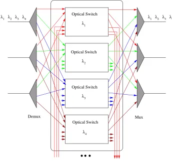
all-optical OXC. The signals coming in over different fibers are first demultiplexed. All the
signals at a particular wavelength are sent to an optical switch dedicated for that wavelength.
The signals from the outputs of the optical switches are multiplexed back together onto the
outgoing fibers. If W is the number of wavelengths each fiber carries and P the number
of incoming/outgoing fibers,W mux-demux pairs andW 2P ×2P switches are required to
implement the OXC shown in the figure. The 2P ×2P optical switches can be configured
such that any wavelengths can be added or dropped locally from and to any fiber. With
this configuration most of the switching is in the optical domain, minimizing the cost and
maximizing the capacity of the network, while allowing us to route the signals down to the
electronic layer for the purposes of low-speed grooming, wavelength conversion and signal
regeneration. It should be noted that what has been presented is a functional description
of the working of an OXC. An optical cross-connect may be implemented differently (for
example, using MEMS mirrors), but the essential function remains the same.
The rapid advancement and evolution of optical technologies makes it possible to
move beyond point-to-point WDM transmission systems to an all-optical backbone network
that can take full advantage of the available bandwidth by relaxing the need for per-hop
packet forwarding. Typically, the backbone network comprises of several high-speed routers
interconnected as SONET ring networks and such rings themselves interconnected to form
rings of rings. However, with the advent of the optical cross-connect slowly the trend is
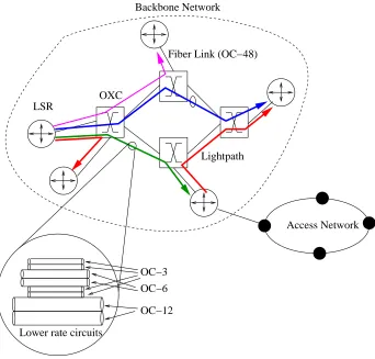
shifting towards a generalized arbitrary mesh topology as shown in Figure 2.4. Such a
network consists of a number of optical cross-connects (OXCs) arranged in some arbitrary
topology. Each OXC can switch the optical signal coming in on a wavelength of an input
fiber link to the same wavelength in an output fiber link. The OXC may also be equipped
with converters that permit it to switch the optical signal on an incoming wavelength of
an input fiber to some other wavelength on an output fiber link. The main mechanism of
transport in such a network is the lightpath, which is a communication channel established
between two LSRs (or other edge devices) over the network of OXCs, and which may
span a number of fiber links. A lightpath is a generalization of the MPLS concept of a
label-switched path (LSP) with the wavelength color corresponding to the label and the
cross-connect matrix corresponding to the label forwarding table [11, 22]. Lightpaths are
setup between different LSRs by appropriately configuring the LSRs and the OXCs in the
network. The lightpaths usually carry several lower rate circuits so that its bandwidth is
1
λ λ2 λ3 λ4 λ4
λ3 λ2 λ1
Demux
wavelength conversion and regeneration Local add/drop for low−speed grooming,
Mux Optical Switch
λ
4
λ
3
λ
2
λ
1
Optical Switch Optical Switch Optical Switch
Figure 2.3: An all-optical OXC with local add/drop
access networks sink and source traffic to and from the backbone network. To the backbone
network it appears as if the LSR is generating all the traffic. Thus, in the current context
a ‘node’ usually refers to the LSR and the access network it is connected to. Since the
abstraction does not alter the problem, such an assumption is made for the purpose of
succinctness.
2.1.2 Translucent Optical Networks
Opaque nodes are known to have several problems associated with them. The
OXC LSR
Fiber Link (OC−48)
Access Network Lightpath
Lower rate circuits
OC−3 OC−6
OC−12
Backbone Network
Figure 2.4: A typical optical network
deploy due to high interconnection costs, power consumption and space requirements. As
illustrated in [16] having none of the nodes perform any electronic routing is also not a viable
solution. Thus, the networks need to be equipped withtranslucent nodes. These nodes from
operations, administration and management (OAM) perspective should be as identical in
capability as possible. Also, as observed in [15] network configurations comprising of opaque
nodes tend to be optimal in terms of cost for a given set of traffic demands but not for a
different set. From a reconfiguration viewpoint, each node must be equipped to handle the
worst routing load of any node. A practical approach to address all these issues would be
to design networks so that cost of the node equipped with most LTE is minimized, thus
relieving the most loaded node in the network and then equipping each node with the same
Translucence can be considered to have several dimensions to it; the number of
lightpaths a node terminates, referred to as the nodal degree of opacity (or simply, nodal
degree), is one such dimension. Very few studies consider nodal degree constraints in its
research [35]. In topologies more connected than the simple path and ring networks, nodes
may have several input ports and output ports. For such nodes, the nodal degree alone is
not an indicator of the node’s translucence; the number of wavelengths terminated must
be as balanced as possible across the different ports and not concentrated at a few ports.
Studies in translucent network design are relatively few [4] and research in the area is very
nascent.
2.2
Virtual Topology Design
Often computer networks are viewed from a graph theoretic viewpoint as a graph.
The vertices of such a graph typically represent routers, switches etc., and the graph edges
the physical links. The graph equivalent of a computer network denotes the physical
topol-ogy of the network. In optical WDM networks, the graph denoting the physical topoltopol-ogy of
the network has an edge between nodes if there exists an optical fiber connecting the nodes.
Selectively optically bypassing certain wavelengths at certain nodes in optical networks,
in-troduces the concept oflogical orvirtual connectivity between the endpoints of a lightpath;
while the two nodes are not physically connected directly, the absence of any interruption
or electronic conversion in the channel between the nodeslogically connects them. A graph
connecting nodes that are logically or virtually connected can be obtained for a configured
optical network. A graph thus obtained is said to denote the logical or virtual topology of
the network. The logical topology hides the details of the physical topology. A given
phys-ical topology can be used to realize several logphys-ical topologies and similarly, a given logphys-ical
topology can realized using several different physical networks.
One of the major concerns for service providers has been to build a logical topology
(or stated differently to determine what lightpaths need to be set up) that can satisfy the
requirements of the upper layers. The virtual topology design problem has similarities with
several topology design problems [14]. An elaborate survey of research in the area of virtual
topology design can be found in [14]. In general, the virtual topology design problem can
metric of interest such as throughput, amount of electronic routing or the amount of LTE
used.
The fact that a given physical topology can be used to realize several logical
topologies, implies that optical networks lend themselves very well to reconfigurability.
Indeed, reconfigurability is seen as one of the salient strengths of optical networks. A
virtual topology is designed on the basis of observed patterns in traffic for a given physical
topology. Being able to realize a different virtual topology on the same physical topology
provides adaptability (when traffic patterns change), self-healing capability (when physical
topology changes due to failure of components) and upgradability. The virtual topology
design problem is known to be NP-complete because it is in essence an m-commodity flow
problem. Hence, several heuristic solutions have been proposed in literature.
2.3
Traffic Grooming
With the deployment of commercial WDM systems, it has become apparent that
the cost of network components, especially line terminating equipment (LTE), is a dominant
cost in building optical networks, and is a more meaningful metric to optimize than, say,
the number of wavelengths. Furthermore, with currently available optical technology, the
data rate of each wavelength is of the order of 2.5-10 Gbps, while channels operating at
40 Gbps will be commercially available in the near future. In order to efficiently utilize
the capacity of each lightpath, a number of independent lower-rate traffic streams must be
multiplexed into a single lightpath. These observations give rise to the concept of traffic
grooming, which refers to the techniques used to combine lower speed components onto available wavelengths in order to meet network design goals such as cost minimization.
Traffic grooming has received considerable attention recently, and due to the widespread use
of SONET/SDH networks, much of the early work on WDM traffic grooming has focused
on ring topologies [3, 6, 15, 17, 19, 21, 27–29, 37, 41, 42, 46, 47]. For reviews of the traffic
grooming problem area, see [16, 33, 50]; [16] also provides a detailed example and a precise
formulation.
An instance of the traffic grooming problem is specified by, one, the traffic demand
matrix specifying the amount of traffic that flows between all nodes in the network, two, the
grooming factor and finally, a relevant objective (typically cost) function. The elements of
the traffic demand matrix represent aggregate traffic between the various source-destination
pairs in multiples of some base rate and the grooming factor represents the bandwidth of a
single wavelength in multiples of the same unit. An instance of the traffic grooming problem
can conceptually be considered to comprise of the following three subproblems (SPs):
1. Virtual topology SP: The SP comprises of determining a set of lightpaths that need to be set up to satisfy the given traffic requirements. The set of lightpaths
determine the virtual topology to be realized and can be represented as a directed
graph, Gv(V, Ev) with Ev comprising of unweighted edges between nodes that are
connected by a lightpath and V comprising of vertices each of which corresponds to
a node in the network.
2. Lightpath routing and wavelength assignment SP: The RWA SP concerns assigning a path of links and a wavelength on each of the links for each of a multiset
of lightpaths. One version of the RWA SP assigns the same wavelengths in all the
links of a lightpath. Such an assignment is said to obey the wavelength continuity
constraint. The version of RWA SP that does not enforce the constraints requires the
nodes to be equipped with wavelength converters to convert signal on wavelength to
another. The RWA SP is NP-hard in general network topologies [24]. Polynomial
time algorithms exist to solve the RWA SP for simpler elemental topologies such as
the path [23], star [44] and spider networks [45]. The RWA SP is known to be
NP-hard for tree networks though the routing aspect of the SP is solvable in polynomial
time [9]. The RWA SP in ring networks is NP-hard [45].
3. Traffic routing SP: The traffic routing SP concerns routing the sub-wavelength traffic demands of a source-destination pair to one or more lightpaths set up. This
problem too is inherently hard. Even in the simplest physical topology, the path
net-work, in which the RWA SP can be solved in polynomial time, the traffic grooming
problem is NP-hard even when a candidate virtual topology is provided [13]. The
fact that even when two of the SPs of traffic grooming are eliminated (virtual
topol-ogy design and RWA) traffic grooming is hard, implies the traffic routing problem is
inherently hard, even in its simplest form.
can be obtained only by considering all the three SPs in an integrated manner. However,
due to the inherent hardness of the problem the practical approach taken is to solve the
SPs separately and then combine the sub-solutions to obtain a feasible solution. Note that
arbitrarily solving the three SPs separately and then trying to combine may not in general
provide feasible solutions.
Traffic grooming has been studied for several different objective functions. Below,
we discuss some of the practically relevant cost functions.
2.3.1 Grooming Cost Functions
In the existing literature, LTE cost minimization is addressed by formulating the
problem so that its objective reflects either the number of LTEs directly, or in a more indirect
way by minimizing the amount of electronic (as opposed to optical) routing performed.
However, most existing studies only concentrate on some aggregate representation of these.
That is, the total number of LTEs (or the total amount of electronic routing performed)
over all the network nodes is minimized. Listed below are three cost functions that are
relevant and minimization of these have been considered in literature:
1. Total number of lightpaths: Each lightpath endpoint requires a transceiver at its origin and terminal node. Thus, the fewer the total number of lightpaths in the whole
network, the fewer the number of transceivers in the whole network which translates
to a reduced total network cost. An alternative measure is the total amount of LTE
(SONET ADMs while considering SONET ring networks) used. This is the cost
function used in [3, 26, 41].
2. Total amount of electronic switching: This cost model tries to reduce the total electronic routing in the network. Each time a lightpath is terminated, the model
accounts for the number of traffic streams the lightpath carried, as the amount of
electronic routing the lightpath termination resulted in. This model also indirectly
captures the total LTE cost. This has been studied in [15]. The advantages of
in-troducing electronic switching within the network is twofold: it increases the virtual
connectivity between the various nodes in the network while reducing the wavelength
requirements within the network; the trade-off is increased cost due to the introduction
3. Maximum number of wavelengths added/dropped by a network node: This cost model sets a limit on the cost of any single node in the network. For this and
several reasons cited in Section 2.1.2, this of greater practical interest than others. The
only known study that has previously considered this cost function in the context of
traffic grooming is [4].
While the first two cost functions are important metrics, they result in solutions
comprising of opaque nodes or nodes with high nodal degree. Such nodes are undesirable
for several reasons discussed in Section 2.1.2. As suggested in [16] a more relevant cost
function/objective that needs to be optimized is the cost of the node equipped with the
most LTE or more simply, to minimize the maximumnodal degree of the network.
In this thesis we consider the problem of grooming solutions for WDM rings
net-works with subwavelength traffic, with the objective of minimizing the maximum opacity
of any node in the network.
2.4
Traffic Grooming Literature Survey
In this section we briefly review and survey recent literature in the area of traffic
grooming in general. We then briefly discuss some decomposition approaches that have been
employed for traffic grooming and how these approaches are special cases of our approaches.
2.4.1 General Approaches
The static version of the problem is a network design problem—a problem of
how best to configure the network to support the estimated traffic matrix. Typically, an
estimated traffic matrix is itself obtained from several different estimates of traffic in the
network. The dynamic version of the problem, on the other hand is mostly one of how
best to set up connections (lightpaths) so as to cause the least average blocking probability.
Most of the research considers the network design aspect of grooming rather than blocking
characteristics for dynamic traffic. Most studies have considered the static version of the
problem [6, 8, 15, 17, 18, 20, 27, 29, 37, 38, 41, 42, 47, 48]. There have been a few studies that
The grooming problem being NP-complete, all solutions proposed in the literature
are sub-optimal, in general but for specific scenarios (however unrealistic) optimal solutions
are obtainable and have been proposed [5]. The approaches in literature are mainly one
of three kinds: heuristics specific to traffic grooming, decomposition based approaches and
solutions based on transforming the grooming problem to a different well known problem
and then employing heuristic solutions proposed in those contexts.
Several heuristic solutions that specifically address grooming (as opposed to those
that employ meta-heuristics like genetic programming etc.) [3, 5, 20, 42, 49] have been
pro-posed in literature. Typically, the performance of the heuristics is studied for different
traffic patterns and compared with theoretical bounds. A few of the studies have accorded
a rigorous theoretical analysis of the heuristic solutions proposed [25, 41] and provided
ap-proximation ratios for the heuristic algorithms.
As stated earlier the grooming problem comprises of three other hard problems
which need to be considered in an integrated manner to obtain the optimal solution. The
decomposition based approaches, break down the grooming problem by ignoring some of
the constraints of the problem and considering the three problems in isolation. This
signif-icantly reduces the complexity of the problem but at the cost of sub-optimality. Some of
the constraints become trivial or computationally tractable for certain topologies e.g. the
routing constraints in the RWA SP for the unidirectional ring or path network. Wavelength
assignment is solvable in polynomial time in path networks [23]. Thus, the RWA SP is
completely eliminated in path networks. One of the approaches in literature has been to
consider complex topologies as consisting of simpler topologies (solving which is relatively
easier) and to combine solutions to several instances of the simpler topology to obtain an
approximate solution for the more complex topology. Finally, some of the studies employ
meta-heuristics such as simulated-annealing and genetic algorithms to solve the grooming
problem [42]. Since our approaches are based on decomposition , in Section 2.4.2 we discuss
in greater detail similar approaches that can be found in literature.
2.4.2 Decomposition Approaches to Traffic Grooming
There have been a few studies looking at more generalized (in terms of the
topolo-gies and technolotopolo-gies involved) [32,36,43,49] and practical problems [4]in the traffic
addresses the specific problem we have addressed in this work [4]. In fact, one of the
approaches presented here transforms the ring traffic grooming problem into several path
grooming problems and employs the path grooming algorithm proposed in [4] to solve them.
The solution techniques we have proposed are decompositional in nature. Broadly
speaking, the decomposition techniques comprise of approximating the original harder
prob-lem into several smaller probprob-lems that are relatively easier to solve. In this sense, our work
bears similarity with several others found in literature [3,15,21,37,48] but is novel in that it
is a generalization of these decomposition approaches and is being presented in a different
context with an objective very different from those addressed by these works.
Berry and Modiano’s [3] work wherein each wavelength is dropped by a given set
of nodes, reduces the problem to one of determining how the nodes should be grouped
and what wavelengths they should be assigned. Chiu and Modiano [6] have presented an
heuristic algorithm to minimize the total number of LTEs used in the network when all the
nodes have the same amount of traffic to each other. This technique involves grouping nodes
and then grooming traffic between nodes belonging to same groups and traffic between the
groups independently. Simmons et al [37] introduce the concept of super-node which is a
collection of several contiguous nodes chosen such that traffic between super-nodes is as
close as possible to the bandwidth of a single lightpath. The algorithm of [37] groups only
contiguous nodes while this is not always beneficial (as has been shown in Section 4.3.1).
Thus, the idea of grouping nodes has been proposed in contexts related to traffic grooming
and in fact, other contexts [34] too. However, these other works in literature are special
cases of the first decomposition approach we have proposed, node grouping. We present
an intuitive argument and theoretical analysis for some specific traffic patterns, outlining
the benefits of such grouping techniques. While none of these studies examine the min-max
objective, they are also restrictive in that they explore traffic patterns which are a subset
of the ones we consider.
Ghafouri-Shiraz et al [21] and Zhang and Qiao [48] have studied grooming traffic
to reduce the total network cost by reducing the number of LTE used. Both works use
the concept ofcircles which are non-overlapping connections that are grouped together and
then grooming several of these circles together onto a given set of nodes while attempting
to reduce the number of SONET ADMs used. These approaches are again special cases
of our second decomposition approach—traffic slicing. Grooming traffic belonging to each
Qiao and Ghafouri-Shiraz et al but is different in the objective, the actual technique used
and also in that the two works tackle wavelength assignment by treating it independently
of grooming whereas our approach is to trivialize wavelength assignment by transforming
the ring into a path instance.
The technique of transforming an instance of ring grooming into one of solving
several path grooming instances and then combining these has also been explored by Dutta
and Rouskas [15] in the context of traffic grooming with the objective of reducing total
electronic routing in the network. However, our approach results in several path instances
each of which contains exactly one node more then the original ring problem as compared
to their approach which contains several small path segments which together form the ring.
Our approach is to transform a ring instance into several path instances of almost the same
size, solving for the path instances heuristically and then combining the results whereas their
approach is to decompose the ring into several smaller path segments, solve them optimally
(using mixed integer linear programming techniques) and combine these results to obtain
solutions for larger and larger path networks that more closely resemble the original ring
instance.
Our node grouping technique is a generalization of several algorithms presented
in literature. Our traffic slicing technique has some similarity with other works presented.
The traffic slicing technique is in fact a generalization of the node grouping technique as
illustrated in Chapter 5. These decomposition techniques are general in nature and have
Chapter 3
Problem Definition
3.1
Traffic Grooming with Min-Max Objective
Below we define precisely the problem that we consider, using notation generally
consistent with [16], explaining where necessary.
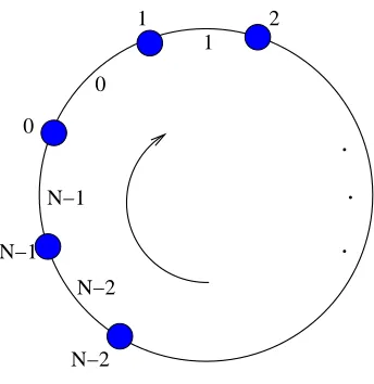
We consider a unidirectional ringRwithNnodes, numbered from 0 toN−1. (This
is a practically important case because even if fiber links exist in the reverse direction, they
may be reserved for protection purposes, or an OAM policy decision such as shortest path
routing might decompose a bidirectional ring problem to two unidirectional ring problems.)
The fiber link between each pair of nodes can support W wavelengths, and carries traffic
in the clockwise direction; in other words, data flows from a node ito the next nodei+ 1
modulo-N on the ring. The links ofRare numbered from 0 toN−1, such that the link from
nodeito node i+ 1 modulo-N is numberedias shown in Figure 3.1. Each node in the ring
is equipped with a wavelength add/drop multiplexer (WADM) (similar to the one shown in
Figure 2.2), which can pass each wavelength through optically, or add/drop it from/to an
electronic cross-connect. Each add/drop wavelength requires an LTE. We assume that the
wavelength continuity constraint applies, that is each lightpath is constrained to use the
same wavelength over each physical link it traverses.
The problem we consider is that of grooming low speed traffic components onto
.
.
.
N−2 0
1
N−2 N−1
N−1 0
1 2
Figure 3.1: AnN-node unidirectional ring network
among all the nodes in the network. We consider the static traffic scenario, that is it is
assumed that the traffic demand from each node to each node of the network is known
or estimated a priori and a static virtual topology and grooming solution is desired to be
designed to carry this traffic. The traffic demands between pairs of nodes in the ring are
given in the traffic matrixT = [t(sd)]. We assume that the network supports traffic streams
at rates that are a multiple of some basic rate (e.g., OC-3). We letC denote the capacity
of each wavelength expressed in units of this basic rate. Thus, C denotes the maximum
number of traffic units that can be multiplexed on a WDM channel (wavelength). For
example, if each wavelength runs at OC-48 rates and the basic rate is OC-3, thenC = 16.
Each quantityt(sd)∈ {0,1,2,· · · }is also expressed in terms of the basic rate, and it denotes
the number of traffic units that originate at node sand terminate at node d.
We define nodal degree as the maximum of the number of wavelengths that a
node adds or drops and the maximum nodal degree of a network as the maximum of the
nodal degrees of all the nodes. The maximum nodal degree of a network is interchangeably
referred to as itsmaximum nodal opacity. An instance of the grooming problem is specified
by specifying N, W, C and T, and the goal is to obtain the virtual topology and traffic
routing minimizing the maximum nodal degree.
Traffic grooming problems are in general hard, and many variants are NP-Complete.
networks, and therefore for ring networks [4]. Thus for practical purposes good heuristic
algorithms are necessary. In subsequent chapters we describe two heuristic solutions to this
end.
3.2
Assumptions
In this thesis we have assumed the following:
• Each node is equipped with WADMs to selectively optically bypass signals of certain
wavelength(s).
• Each node is equipped with digital cross-connects so that a traffic component arriving
at a node on one wavelength may be switched electronically to a different one as it is
routed to its destination.
• No traffic component traverses all the links in the network i.e. no traffic is carried
beyond the destination node or all around the ring. A more generalized version of
the problem that would allow traffic to be carried around the ring would result in
solutions that use up a lot of bandwidth. In most cases such an assumption will not
make a difference as far as the opacity is concerned. Thus, it is reasonable to assume
no traffic will be routed all around the ring. Many other studies make a similar
assumption [4, 15].
• Wavelength continuity constraint is assumed to hold i.e. a lightpath should be
as-signed the same wavelength on all the links between its endpoints. From a practical
perspective, this means we assume wavelength converters are absent in the network.
While it is generally believed that wavelength conversion provides benefits to
groom-ing, it does add to the cost of the network and in the current context, distributing the
converters among all the nodes in the network so that no single node ends up having
too many converters also becomes a part of the problem. To focus on the grooming
problem, we assume absence of wavelength converters in the network.
In this thesis, one of the heuristic approaches we present is specifically applicable
to certain families of traffic matrices. We characterize a family of matrices bearing some
matrices alone; the second approach is a more generalized one and can be used for any
arbitrary traffic. For the sake of numerically obtaining arbitrary traffic matrices, we say
such matrices possess atraffic pattern: the random traffic pattern. Below we provide formal
definitions of the traffic patterns.
3.2.1 Traffic Pattern Characterization
For the purpose of this study we characterize traffic matrix into the following:
Completely Decomposable/Nearly Completely Decomposable: The defi-nitions of completely decomposable/nearly completely decomposable traffic matrices is
bor-rowed from a similar definition of nearly completely decomposable Markov chains [40, pp.
285 ff.]. A traffic matrixT is considered to be completely decomposable (CD) if the nodes
can be partitioned such that the partition of T can be expressed in the block form where
the elements of the off-diagonal blocks are all zero and not all the elements in each of the
diagonal block are zero. A completely decomposable traffic matrix is consideredmaximally
completely decomposable if none of its diagonal blocks are themselves completely
decom-posable. Nearly completely decomposable (NCD) traffic matrices are similar to completely
decomposable matrices with the difference being that the off-diagonal blocks are nearly
zero. NCD and CD traffic matrices have an inherent locality in that such matrices have
most of traffic flowing between subset of nodes and very little traffic between nodes
belong-ing to different subsets. Henceforth, any reference to localized traffic should be understood
as referring to either CD/NCD traffic matrices. Often it is observed in some networks,
nodes have a lot of traffic destined to a subset of the nodes and relatively little traffic to the
remaining nodes. This traffic pattern is used to capture this property of locality. It should
be noted that by definition this traffic pattern does not restrict traffic locality to nodes that
are placed closely. For example, two nodes placed diametrically apart could exchange a lot
of traffic.
Strictly/Statistically Source-wise Uniform: A traffic matrixT is considered to be strictly source-wise uniform if all the amount of traffic originating from and destined
to all the nodes is the same. There exist three types of strictly source-wise uniform traffic
• Constant strictly source-wise uniform traffic matrices:
t(pq)=
b ∀p, q∈ {0,1· · ·N−1}and p6=q,
0 otherwise. (3.2.1)
whereb is some positive integer.
• Falling strictly source-wise uniform traffic matrices:
t(pq) =
b+ (N −1−(q−p))·d ∀p, q∈ {0,1· · ·N −1} and p < q, b+ (p−q−1)·d ∀p, q∈ {0,1· · ·N −1} and p > q,
0 otherwise
whereb, dare positive integers.
• Rising strictly source-wise uniform traffic matrices:
t(pq) =
b+ (q−p−1)·d ∀p, q∈ {0,1· · ·N −1} and p < q, b+ (N −1−(p−q))·d ∀p, q∈ {0,1· · ·N −1} and p > q,
0 otherwise
whereb, dare positive integers.
While, the three traffic patterns seem to be very different from the other, there
is a commonality between them. Traffic matrices of these patterns have the property that
these matrices result in uniform loading of each of the links in a unidirectional ring network.
For example, consider the following three matrices:
0 1 1 1
1 0 1 1
1 1 0 1
1 1 1 0
,
0 3 2 1
1 0 3 2
2 1 0 3
3 2 1 0
and
0 1 2 3
3 0 1 2
2 3 0 1
1 2 3 0
.
The amount of traffic flowing through each of the links for the three matrices are
6, 10 and 14 respectively. The falling and rising pattern though they give an impression
of non-uniformity in observed traffic they do exhibit uniformity in the sense just discussed.
Thus, we refer to all the three traffic patterns collectively as source-wise uniform traffic.
These traffic patterns distribute the load evenly among all the physical links in
the network. These patterns are relatively simpler to study and analyze than arbitrary
traffic patterns. They are desirable from a practical perspective too. The network can be
Statistically source-wise uniform traffic matrices are similar to strictly source-wise
uniform traffic matrices with the difference being that the matrix elements represent the
mean of the traffic between the source-destination pairs rather than the actual amount of
traffic.
Random Traffic Not all traffic matrices can be classified into one of the above mentioned classes. We classify traffic which cannot be considered either localized or
source-wise uniform as being random. We assume such matrices can be thought of as being
sta-tistically source-wise uniform but with a very high variance. We characterize such matrices
using two parameters: the mean of all the traffic components and the standard deviation
of the traffic components from the mean.
While it is desirable to have traffic demand distributed evenly this is not always
the case. With more and more web applications, data-based and multimedia-based,
com-ing to the fore in the future, traffic demands may become not only non-uniform but also
Chapter 4
Node Grouping
In this chapter we present the first decomposition technique based on grouping
nodes. The approach in the text is interchangeably referred to as either thenode grouping
or the nodal decomposition approach. We describe the approach and how it is applicable
to families of traffic matrices for which the approach performs well. We present a few
theoretical results which support our observations about the node grouping approach.
4.1
Description and Rationale
This approach is based on a simple idea motivated by the CD/NCD traffic patterns:
if the entire set of nodes is composed of some groups that are each composed of nodes that
have a high amount of traffic to each other, but there is comparatively less traffic between
nodes belonging to different such groups, then the opacity (nodal degree) of the nodes can
be reduced considerably simply by dedicating distinct wavelengths to groups, and having
nodes of a group optically pass through wavelengths belonging to other groups. In other
words, a property of locality in the traffic pattern is leveraged. Naturally, we may expect
even more benefit if further grooming is performed so that all nodes of a group need not even
terminate all wavelengths assigned to that group. However, the simple grouping already
has a beneficial effect on the nodal opacity, and it has a very attractive simplicity from
The solution proposed comprises of partitioning the set of nodes with indices
0,1· · ·N −1 into ndisjoint sets/groups G1,G2 · · · Gn. For a given partition, we define the following classes of traffic:
Group-local traffic of group i: All the traffic originating from and destined to nodes
belong to group i.
Group-external traffic of group i: All traffic that either originate from nodes belonging
to group i but are destined to nodes outside the group or traffic originating from nodes
outside the group destined to nodes belonging to group i.
Inter-group traffic: All traffic between nodes belonging to different groups.
Every node terminates two sets of wavelengths - one, the set of wavelengths
re-quired to carry the group’s group-local traffic and the other, the set of wavelengths rere-quired
to carry all the inter-group traffic. Each node can be considered to be opaque with respect to
its group-local traffic. However, the nodes do optically route all group-local traffic of other
groups. This contributes to reducing the opacity/maximum nodal degree (as compared to
the completely opaque case).
LetT = [t(sd)] of orderN×N, represent the traffic matrix whose elements specify
the amount of traffic that flows between the N nodes in the unidirectional ring. Let P =
{G1, G2· · ·Gn} represent a partition of the N nodes of the unidirectional ring. Given a
partitionP and traffic matrixT, we define a set of matrices{H1, H2· · ·Hn}where eachHi
represents the group-local traffic of groupiwhose rows and columns are ordered such that
indices of the nodes whose traffic profile the rows and columns represent are in increasing
order. Hi is a square sub-matrix can be expressed as
Hi=
Hi(11) Hi(12) · · ·
Hi(21) Hi(22) · · ·
. . · · ·
. . · · ·
where the elements Hi(11), Hi(12)· · · of the sub-matrix representing the traffic
be-tween two nodes belonging to the same group, correspond to the respective t(sd) from the
original traffic matrix T.
While considering the group-local traffic of some group i, the nodes of the group
sequence of one or more consecutive physical links. Logical link l of groupiis assumed to
connect thelthnode of the group to the ((l+ 1) mod|G
i|)thnode of the group. The amount
of group-local traffic determines the number of group-local wavelengths required to support
the traffic and is given by
Wi= |Gi|−1
max j=0
& l(j)i
C '
(4.1.1)
where C is the capacity of a single wavelength expressed in the same units as the
traffic components of the traffic matrix andl(j)i is the amount of group-local traffic of group
iflowing through groupi’s logical linkj and is given by
l(j)i =
|Gi|
X
k=2 k−1
X
l=1
H((j+k) mod|Gi|,(j+l) mod|Gi|)
i (4.1.2)
The inter-group traffic determines the number of inter-group wavelengths and is
given by
W0= N−1 max j=0
& l(j)0
C '
(4.1.3)
where C represents the capacity of a single wavelength and l(j)0 represents the
amount of inter-group traffic flowing through the physical linkj and is given by
l0(j)= N
X
k=2 k−1
X
l=1
f((j+k) modN,(j+l) modN) (4.1.4)
where f is given by
f(p, q) =
0 p, q∈Gi for somei,1≤i≤n,
t(pq) otherwise
The maximum nodal degree obtained by employing the decomposition technique
outlined here is given by
∆ =W0+
n max
i=1 (Wi) (4.1.5)
Also, we define the critical group of a particular partition of T as that group
partition of T is defined as the link which has the highestl(j)i and the inter-group critical
link of a particular partition of T is defined as the link which has the highest l(j)0 .
The traffic grooming problem as described earlier comprises of three subproblems
(SPs): the virtual topology design SP, the routing and wavelength assignment SP and the
traffic routing SP. Using the node grouping approach, the solution to the virtual topology
design problem consists of setting up lightpaths between the ‘adjacent’ nodes of a group (i.e.
two nodes that have no nodes belonging to their group in between them). For the
inter-group traffic lightpaths are setup between physically adjacent nodes of the ring. The virtual
topology thus obtained for each group’s group-local traffic and the inter-group traffic is
combined together. The routing part of the RWA SP gets eliminated due to our assumption
of unidirectional rings and shortest path routing. Since we assume the group-local and
inter-group traffic is not groomed, the traffic routing SP also gets eliminated. While wavelength
assignment is in general an NP-Complete problem for the ring topology, in this case we
are guaranteed that the lightpaths we form have a valid coloring by the nature of the way
we form them, as long as the total number of lightpaths traversing each link is within the
number of allowed wavelengths.
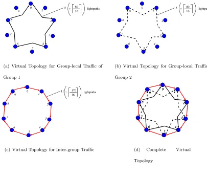
Example: Figures 4.1(a)-4.1(d) show an example of the virtual topology resulting by employing the node grouping approach. The ring comprises of 10 nodes that are grouped
into 2 groups of 5 nodes each with alternate nodes belonging to the same group. It should
be noted that such a decomposition would require more wavelengths than the opaque case.
When the load on the network is very high, the decomposition may yield infeasible solutions.
The group-local and inter-group traffic may each require less thanW wavelengths but when
put together may end up requiring greater thanW wavelengths. Therefore, precaution must
be taken to examine if the decomposition does indeed yield a feasible solution.
Texample =
0 18 16 14 12 10 8 6 4 2
2 0 18 16 14 12 10 8 6 4
4 2 0 18 16 14 12 10 8 6
6 4 2 0 18 16 14 12 10 8
8 6 4 2 0 18 16 14 12 10
10 8 6 4 2 0 18 16 14 12
12 10 8 6 4 2 0 18 16 14
14 12 10 8 6 4 2 0 18 16
16 14 12 10 8 6 4 2 0 18
18 16 14 12 10 8 6 4 2 0
These traffic demands need to be groomed onto the network. The traffic demands
result in 330 units of traffic flowing through each link. For the completely opaque case,
the maximum nodal degree turns out to be 21 (d330/16e, assuming C=16). If the node
grouping approach is employed and adjacent nodes are placed into two different groups, the
traffic grooming problem can be addressed independently for the group-local traffic of the
two groups and the inter-group traffic. The resulting subproblems comprise of grooming
three traffic matrices: two matrices of order 5 representing the group-local traffic of the
two groups, respectively and one matrix of order 10 representing the inter-group traffic.
Specifically, the three matrices are:
H1=
0 16 12 8 4
4 0 16 12 8
8 4 0 16 12
12 8 4 0 16
16 12 8 4 0
H2=
0 16 12 8 4
4 0 16 12 8
8 4 0 16 12
12 8 4 0 16
16 12 8 4 0
F =
0 18 0 14 0 10 0 6 0 2
2 0 18 0 14 0 10 0 6 0
0 2 0 18 0 14 0 10 0 6
6 0 2 0 18 0 14 0 10 0
0 6 0 2 0 18 0 14 0 10
10 0 6 0 2 0 18 0 14 0
0 10 0 6 0 2 0 18 0 14
14 0 10 0 6 0 2 0 18 0
0 14 0 10 0 6 0 2 0 18
18 0 14 0 10 0 6 0 2 0
Using a naive approach (i.e. the no optical routing or the opaque approach)
to groom these matrices and (4.1.1), (4.1.3) results in virtual topologies shown in
Fig-ures 4.1(a)-4.1(c) for the group-local traffic of the two groups and the inter-group traffic,
respectively. Since wavelength assignment for each of the subproblems is carried out
inde-pendently, the three topologies can be combined to obtain the virtual topology shown in
Figure 4.1(d).
4.2
Applicability to CD/NCD Traffic Matrices
The decomposition technique we employ is as described above—of forming groups
of nodes that terminate group-local traffic of only groups they belong to and the
inter-group traffic. While this approach is expected to perform well if the traffic matrix has
the CD/NCD characteristic, we must still decide whether a given traffic matrix has this
characteristic and if so what the appropriate grouping is. To this end, we adapt an idea
from Markov chain theory [40, pp. 285 ff.], namely that of utilizing the coupling information
between states to split the Markov chain into smaller chains that are each strongly coupled
but have little coupling with each other. Simon and Ando [39] were the earliest to employ
these techniques while investigating the dynamics of certain economic models. Courtois [10]
later extended the technique to analyze the performance of computer systems.
In solving Markov chains with huge state space, these techniques partition the