1
Stability Control of a Rotational Inverted Pendulum using
Augmentations with Weighting Functions Based Robust
Control System
Mustefa Jibril1, Messay Tadese2, Eliyas Alemayehu Tadese3
1 Msc, School of Electrical & Computer Engineering, Dire Dawa Institute of Technology, Dire
Dawa, Ethiopia
2 Msc, School of Electrical & Computer Engineering, Dire Dawa Institute of Technology, Dire
Dawa, Ethiopia
3 Msc, Faculty of Electrical & Computer Engineering, Jimma Institute of Technology, Jimma,
Ethiopia
Abstract
This paper mainly analyzes the design and control of the rotational inverted pendulum, and presents a state space expression. Since the system is highly unstable a feedback control system is used. Augmentations with weighting functions based mixed sensetivity and H2 optimal control methods are used to make the system stable for uprise position. The rotational inverted pendulum have been simulated and compared with the proposed controllers and a promising results have been analyzed sussesfuly.
Keywords: inverted pendulum, Augmentation, Mixed sensetivity, H2 optimal 1. Introduction
Inverted pendulum system is a typical multivariable nonlinear strong coupling unstable system. Inorder to control this system, the theory of controlling the system stability, controllability, robustness and tracking the system. Its control method are widly used in military, industry, robot and in the field of general industrial process control, such as the balance in the process of the robot control and satellite attitude control in flight, Inverted pendulum system which is more ideal experimental apparatus control theory is often used to test the effect of the control strategy. This article aims at single stage of nonlinear rotational inverted pendulum control problem, the design has realized the single inverted pendulum with robust control based theory.
2. Mathematical Modelling of the Rotational Pendulum
Figure 1 shows the structural design of the rotational pendulum
2
Figure 1 Rotational Pendulum 2.1 For the DC Motor
Assume
The stator current is constant therefore the magnetic flux is constant
t K If f
1
The motor torque is proportional to the armature current and the flux
1
2m m a a
T t K i t K i
The voltage vb is proportional to the angular speed of the motor
2
3b m
V t K t
Applying KVL to the motor circuit neglecting the coil inductance
4m a b a
R i t V t V t
Substituting Equation (3) in to Equation (4) yields:
2
5m a m a
R i t K t V t
The rotational equation of the motor is
2
1
2 6
m m
m m m a
d t d t
J B T t K i t
dt dt
3
2 2 1 1 7 m m m m ad t d t
J B
i t
K dt K dt
Substitution Equation (7) into Equation (5)
2 2 2 1 1 8m m m
m m
m a
d t d t d t
J B
R K V t
K dt K dt dt
Rearranging Equation (8) becomes
2
2 9
m m
m m a
d t d t
a b V t
dt dt Where 1 2 1 1 m m m m m m m B K a K
R J K
K b R J
2.2For the pendulum
The rotational equation of the pendulum is
2
2 10
P P
P P T
d t d t
J B T t
dt dt
Where
T mP P
T t T t T t
mP
T t Torque of the motor based on the pendulum
P
T t Torque of the pendulum
Torque of the motor based on the pendulum is
3 2 2
11m mP
d t
T t K
dt
Note that the sign of K3 depends on whether the pendulum is in the inverted or non-inverted position.
The torque of the pendulum is
sin
12P P
4
Substituting Equation (11) and Equation (12) into Equation (10) and rearranging yields
2 2 3 2 2 sin 13P P P P m
P P
d t B d t mgl d t
K
dt J dt J dt
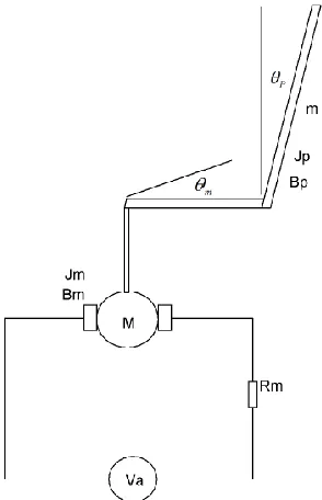
Linearization of these equations about the vertical position (i.e., P= 0), results in the linear, time-invariant state variable model
3 3
0 1 0 0 0
0 0 0
0 0 0 1 0
0
0 0 1 0
m m m m m m a P P
m P m
P P
P P P P
m m P P a b V
K a mgl B K b
J J J J
y
The Values of the parameters of the system is shown in Table 1 below Table 1 System parameters
No Parameter Symbol Value
1 Motor torque constant K1 22.5 Nm/A
2 Motor speed constant K2 0.43 Vs^2/rad
3 Armature resistance Rm 10 ohm
4 Motor damping friction Bm 0.05 Nms/rad
5 Motor inertia Jm 0.03 Nms^2
6 Pendulum inertia JP 0.0013 Nms^2
7 Pendulum damping friction BP 0.003 Nms/rad
8 Torque constant K3 0.0019412
9 Mass of the pendulum m 0.086184 Kg
10 Length of the pendulum l 0.113 m
11 Acceleration due to gravity g 9.8 m/s^2
5
0 1 0 0 0
0 33.04 0 0 74.89
0 0 0 1 0
0 49.3 73.41 2.29 111.74
0 0 1 0
m m m m a P P P P m m P P V y
And the transfer function of the system becomes
3 2-111.7 s + 0.18
35.33 2.252 242
4 5 7
P
a s s s
s G s
V s
3. Proposed Controllers Design
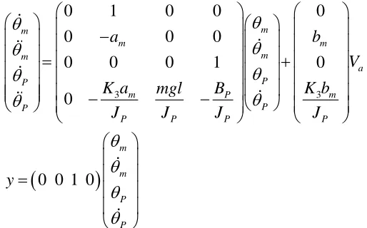
3.1Augmentations of the Model with Weighting Functions
In this section, we will focus on the weighted control structure shown in Figure 2, where W1(s),
W2(s), and W3(s) are weighting functions or weighting filters. We assume that G(s), W1(s), and
W3(s) G(s) are all proper; i.e., they are bounded when s →∞. It can be seen that the weighting
6
Figure 2 weighted control structure with the proposed controllers The weighting function W1(s), W2(s), and W3(s) are chosen as
1 2 3
3 5 2
5 1 10 15 25
s s s
W s W s W s
s s s
The H 2 optimal controller become
2
5 4 3 2
6 5 4 3 2
325.4 2.23 04 4.691 05 2.952 06 1.894 06 2.662 05
100.8 4132 4.724 04 1.72 05 3.395 05 6.066 04
cH
s e s e s e s e s e
s s s e s e s e s e
G
The Mixed sensitivity controller become:
5 4 3 2
6 5 4 3 2
736.2 5.031 04 1.052 06 6.473 06 3.024 06 2.179 04
119 5830 6.344 04 6.39 05 1.197 06 2.133 05
cMix
s e s e s e s e s e
s s s e s e e s
G
s e
4. Result and Discussion
4.1Open Loop Response of the Rotational Pendulum
7
Figure 3 Open loop impulse response of the rotational pendulum
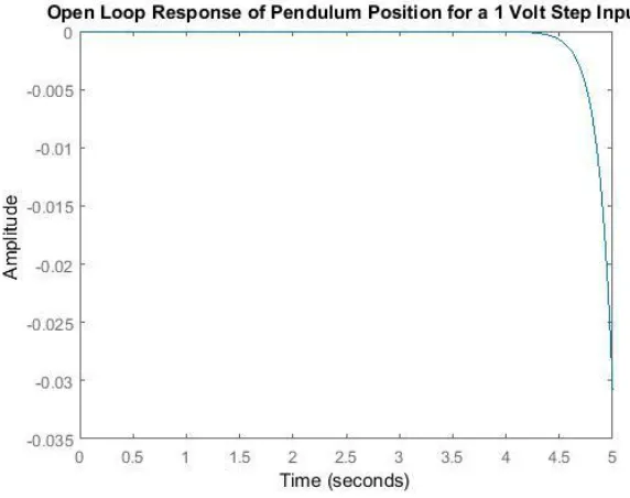
The open loop response for a step input of the rotational pendulum is shown in Figure 4 below.
Figure 4 Open loop step response of the rotational pendulum
The simulation results of the open loop system shows that the rotational pendulum is unstable so the need of feedback control system is essential.
8
The simulation result of the rotational pendulum with mixed sensitivity and H2 optimal controllers for an impulse input voltage signal is shown in Figure 5 below.
Figure 5 Impulse response of the rotational pendulum
The simulation result shows that the rotational pendulum with H2 optimal controller improve the settling time and the overshoot and the angular position returns to zero means the rotational pendulum is in upward stable position.
4.3Comparison of the Rotational Pendulum with Mixed Sensitivity and H2 Optimal Controllers for a Step Input Voltage
9
Figure 6 Step response of the rotational pendulum
The simulation result shows that the rotational pendulum with H2 optimal controller improve the settling time and the overshoot and the angular position returns to zero means the rotational pendulum is in upward stable position.
5. Conclusion
In this paper, modeling, simulation and comparison of the rotational inverted pendulum have been done using Matlab/Script Toolbox. Augmentations with weighting functions based mixed sensitivity and H2 optimal controllers have been used to control the system instability. The open loop response of the system for a step and impulse voltage input shows that the system is unstable. Comparison of the rotational inverted pendulum with mixed sensitivity and H2 optimal controllers have been done for a step and impulse voltage input and the simulation results prove that the rotational inverted pendulum with H2 optimal controller improves the settling time and overshoot and the angular position returns to its position successfully.
Reference
[1].Mustefa Jibril et al. “Robust Control Theory Based Performance Investigation of an Inverted Pendulum System using Simulink” International Journal of Advance Research and Innovative Ideas in Education, Vol. 6, Issue 2, pp. 808-814, 2020.
[2].Omer Saleem et al. “Robust Stabilization of Rotary Inverted Pendulum using Intelligently Optimised Nonlinear Self Adaptive Dual Fractional Order PD Controllers” International Journal of Systems Science, Vol. 50, Issue 7, pp. 1399-1414, 2019.
10
[4].Neha Gupta et al. “Modeling and Simulation of Rotary Rotary Planer Inverted Pendulum” Journal of Physics Conference Series, Vol. 1240:012089, 2019.
[5].Jie Wen et al. “Stabilizing a Rotary Inverted Pendulum Based on Logarithmic Lyapunov Function” Journal of Control Science and Engineering, Vol. 2017, 11 pages, 2017.
[6].J L Duart et al. “Dynamic Modeling and Simulation of a Rotational Inverted Pendulum” Journal of Physics: Conference Series, Vol. 792, VIII, 2016.