OPTIMIZING AND PREDICTING SURFACE ROUGHNESS ON MILLING MACHINE BY USING TAGUCHI &
ANN ON D2 STEEL
Er. Alamdeep Cheema*, Er. Rajiv Kumar**
* Post Graduate student in Industrial and Production Engineering at GIMT, Kurukshetra.
** Assistant Professor in Mechanical engineering department at GIMT, Kurukshetra.
ABSTRACT
Optimization means to find best value of input. For this Taguchi method gives the best output result.
ANOVA is the most effecting parameter. This parameter affects the most among all the input
parameters. Modeling is done by ANN. It is best network model which gives minimum error between
network output and real output. Prediction is done by both methods. Result of both methods is
compared. Best method is used which gives the minimum error. Milling process is used here because
milling is most commonly used in industries. It can perform many tasks. D2 steel is used here. Various
parameter are considered in this are taken from the previous papers. Taguchi and ANN methods are
used because these are the most famous and developing methods. Taguchi method is used for
optimization. It is done by studying the mathematical relation between input and output. Signal to noise
ratio is basically considered in the optimization process. Signal should be large and noise should be less.
ANN method is used for prediction. It shows that for any value of input data we can easily predict the
output with minimum error.
I. INTRODUCTION
Recent functionality requirements have led to development of components with varying free-form
features. Sculptured surfaces have free-form features with both convex and concave regions that can be
geometrically fitted by ball-end cutter. The parts with free from geometric features are generally
machined using ball-end cutters, which are used to manufacture parts in die/mould, aerospace,
biomedical and automotive industries where both part quality and manufacturing time are metrics for
high productivity. The ultimate goal of virtual machining process research is to identify process related
issues and solve them before the costly physical trials in the shop. Modeling the process mathematically
is necessary to achieve that goal in a Reasonable amount of time and the first step of process modeling
is to model the mechanics of the operation that leads to the prediction of the cutting forces experienced
by the cutting tool and the work-piece.
II. LITERATURE REVIEW
R. Peres et.al. (1999) proposed that process optimization is a very important subject to several
industrial sectors in confronting the growth on markets competition. However, due to the complexity of
some processes, their optimization is not an easy task; therefore, to accomplish this objective,
intelligent techniques should be used. We are working on end-milling process optimization through
combining analytic and fuzzy techniques.
J. F. Briceno et.al. (2002) proposed that two supervised neural networks are used to estimate the forces
developed during milling. These two Artificial Neural Networks (ANNs) are compared based on a cost
function that relates the size of the training data to the accuracy of the model.
H. E. Mounayri et.al. (2005) proposed an integrated product development system for optimized CNC
ball end milling is presented. First, the developed model is extended from flat end milling to ball end
milling. Second, the optimization is extended from 2D (speed and feed) to 3 (1/2) D (speed, feed, radial
and axial depths of cut).
K.Kadirgama et.al. (2008) is concerned with optimization of the surface roughness when milling Mould
Aluminum alloys (AA6061-T6) with carbide coated inserts. Optimization of milling is very useful to
reduce cost and time for machining mould. The approach is based on Response Surface Method (RSM)
S.Brevern et.al. (2009) proposed that the world of manufacturing has shifted its level to the era of
space age machining. The purpose of this investigation is to develop Fuzzy based Graphical User
Interface (GUI) for modeling of laser machining conditions.
M.S. Yazdi et.al. (2010) studied that the selection of optimal machining parameters (i.e., spindle speed,
depth of cut and feed rate) for face milling operations was investigated in order to minimize the surface
roughness and to maximize the material removal rate. Effects of selected parameters on process
variables (i.e., surface roughness and material removal rate) were investigated using Response Surface
Methodology (RSM) and artificial neural networks.
S.Moshat et.al. (2010) proposed that End milling is the most important milling operation, widely used in
most of the manufacturing industries due to its capability of producing complex geometric surfaces with
reasonable accuracy and surface finish. However, with the inventions of CNC milling machine, the
flexibility has been adopted along with versatility in end milling process.
B. S.Reddy et.al. (2011) proposed that Pre-hardened steel (P20) is a widely used material in the
production of moulds/dies due to less wear resistance and used for large components. In this study,
minimization of surface roughness has been investigated by integrating design of experiment method,
Response surface methodology (RSM) and genetic algorithm.
A. K.Gupta et.al. (2011) proposed that the optimum combination of machining parameters has been
analyzed for maximizing the tool life with the constraints of material removal rate (MRR) and surface
finish. To optimize these parameters the correct relationship of process parameters with tool life has
been found. Mathematical relations have been developed for predicting the objectives with different
combinations of parameters under the specified constraints. As there is a variety of milling processes,
cutting tool geometries, cutting tool material, work piece material and machine tool conditions, hence
difficult to develop a single robust analytical relation for tool life.
P.Maurya et.al. (2012) studied on CNC end milling, influence of various machining parameters like, tool
feed (mm/min),tool speed (rpm), tool diameter (mm) and depth of cut (mm). In the present study,
experiments are conducted on AL 6351 –T6material with three levels and four factors to optimize
process parameter and surface roughness
S. Hossain et. al. (2012) proposed that Surface roughness is an index which determines the quality of
roughness (Ra) value for Aluminum after ball end milling operation has been measured. 84 experiments
have been conducted varying cutter axis inclination angle (φ degree), spindle speed (S rpm), feed rate
(mm/min), radial depth of cut (feed f mm), and axial depth of cut (t mm) in order to find Ra. This data
has been divided into two sets on a random basis; 68 training data set and 16 testing data set.
A.Behera et. al. (2012) proposed that Plasma spraying technique has become a subject of intense
research in many industrial structural/functional applications because its peculiarity surface properties.
This investigation explains about plasma sprayed copper surface property. Here industrial waste and low
grade ore (i.e. Flay-ash+ quartz+ limonite), used as deposit material which is to be coated on copper
substrates. In many applications, it is found that for structural modification, surface roughness &
porosity parameters are very important. To decrease both surface roughness and coating porosity by
optimizing other necessary properties, different soft computing methods like Artificial Neural Network
(ANN) and Least Square support vector machine techniques used.
III. EXPERIMENTAL DETAILS
End Milling
Among different types of milling processes, end milling is one of the most vital and common metal
cutting operations used for machining parts because of its capability to remove materials at faster rate
with a reasonably good surface quality. Also, it is capable of producing a variety of configurations using
milling cutter. In end milling, the cutter, called end mill, has a diameter less than the work piece width.
The end mill has helical cutting edges carried over onto the cylindrical cutter surface. End mills with flat
ends (so called squire-end mills) are used to produce pockets, closed or end key slots, etc.
In end milling an end mill makes either peripheral or slot cuts, determined by the step-over distance,
complex surface contour. The depth of the feature may be machined in a single pass or may be reached
by machining at a smaller axial depth of cut and making multiple passes.
Material Used
In this work hardened AISI D2 steel (hardness 50-70 HRC) will be used as the work piece material
and Tungsten carbide preferably coated will be used as the tool material. Because increasing tool life is
main concern of hard machining to decrease the cost of the machining process. A particular amount of
maximum flank wear say 0.2 to 0.3 µm can be used as the tool life failure criterion. Flank wear can be
measured using toolmaker’s microscope. The chemical composition of AISI D2 tool steel is given in
below Table 3.1.
Table 3.1 Chemical Composition of Steel
Carbon Silicon Manganese Chromium Molybdenum Vanadium
1.55 % 0.30 % 0.35 % 12 % 0.75 % 0.90%
AISI D2 is recommended for tools requiring very high wear resistance, combined with moderate
toughness (shock-resistance). AISI D2 can be supplied in various finishes, including the hot-rolled,
pre-machined and fine pre-machined condition forming Dies, Punches, Forming Rolls, Knives, Slitters, Shear
blades.
Machine Used
Machining was carried out in CNC machine at CTR, Ludhiana.
Table 3.2 Specification of CNC Milling Machine
Table Size 915 * 356 mm
Table Load 341 KG
Power 3 phase, 60 Hz
Control GE FANUC 211
X Axis Travel 560 mm
Y Axis Travel 406 mm
Z Axis Travel 508 mm
Spindle Speed 100 RPM Direct Drive
Spindle Diameter 65 mm
Spindle Taper ISO-40
Tool Taper BT-40
Magazine Capacity 22 Tools
Maximum Wt. of Tool Holder
50 KG
Maximum Tool Length 254
Table 3.3 Levels of Input Control Parameters
Factors Levels Factor Level values
Speed (rpm) 3 500,750,1000
Depth of Cut (mm) 3 0.75,0.50,0.25
Feed (mm/min) 3 750,1000,1250
The optimum condition is identified by studying the main effects of each of the parameters. The main
effects indicate the general trend of influence of each parameter. The knowledge of contribution of
individual parameters is a key in deciding the nature of control to be established on a production
process. Orthogonal Array is a statistical method of defining parameters that converts test areas into
factors and levels. Test design using orthogonal array creates an efficient and concise test suite with
fewer test cases without compromising test coverage. An orthogonal array is a "table" (array) whose
entries come from a fixed finite set of symbols (typically, {1,2,..., n}), arranged in such a way that there
is an integer t so that for every selection of t columns of the table, all ordered t-tuples of the symbols,
formed by taking the entries in each row restricted to these columns, appear the same number of times.
The number t is called the strength of the orthogonal array. The Table 3.4 shows the design matrix used
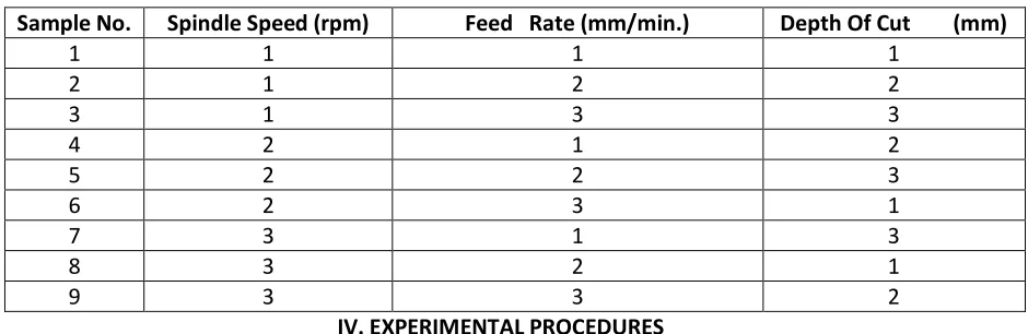
Table 3.4 Orthogonal Array L9
Sample No. Spindle Speed (rpm) Feed Rate (mm/min.) Depth Of Cut (mm)
1 1 1 1
2 1 2 2
3 1 3 3
4 2 1 2
5 2 2 3
6 2 3 1
7 3 1 3
8 3 2 1
9 3 3 2
IV. EXPERIMENTAL PROCEDURES
Checking and preparing the Centre Lathe ready for performing the machining operation. Firstly, the work-piece was cut according to above mentioned dimension i.e. 100*100*25 mm by
cutter of diameter 32 mm.
For developing models on the basis of experimental data three main machining parameters are
considered to predict surface roughness of D2 material using carbide tool. Among the range of
spindle speed, feed, and depth of cut available possible in the machine the following three levels
are considered as shown in Table 3.3.
The machining was carried out on end milling machine, the material work piece is clamped on
vice mounted on the table of the machine. The machining process and work tool motion of the
end milling process respectively.
The machining is carried out by selecting proper spindle speed and feed rate during each
experimentation. Experiment was carried out by varying the depth of cut.
Taguchi's designs aimed to allow greater understanding of variation than did many of the
traditional designs. Taguchi contended that conventional sampling is inadequate here as there is
no way of obtaining a random sample of future conditions. Taguchi suggests a three-stage process: System design,
Parameter design, Tolerance design.
System design is the conceptualization and synthesis of a product or process to be used. In
parameter design the system variables are experimentally analyzed to determine how the product or
approach. The final step in Taguchi’s robust design approach is tolerance design; tolerance design occurs
when the tolerances for the products or process are established to minimize the sum of the
manufacturing and lifetime costs of the product or process.
Taguchi proposed extending each experiment with an "outer array" or orthogonal array should
simulate the random environment in which the experiment would function. Here we use L9 orthogonal
array with 3 levels. In this work, L9 Orthogonal Array design matrix is used to set the control parameters
to evaluate the process performance. Taguchi orthogonal array is designed with three levels of turning
parameters with the help of software Minitab. Orthogonal Array design of experiment has been found
suitable in the present work.
V. RESULTS AND DISCUSSION
End milling is one of the most fundamental and commonly encountered chip removal operations
occurring in a real manufacturing environment. In this machining process, the surface finish is a key
factor in evaluating and determining the quality of a part. In practice, a desired surface roughness value
is usually designated, and the appropriate cutting parameters are selected to achieve the desired quality
of a specified part. The single point incremental forming (SPIF) process is performed on three-axis CNC
machine.
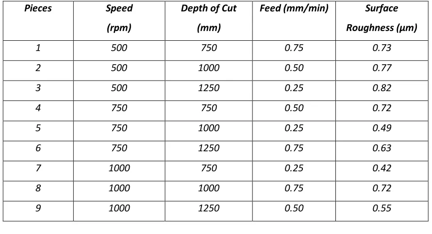
Table 5.1 Measured Surface Roughness
Pieces Speed
(rpm)
Depth of Cut
(mm)
Feed (mm/min) Surface
Roughness (µm)
1 500 750 0.75 0.73
2 500 1000 0.50 0.77
3 500 1250 0.25 0.82
4 750 750 0.50 0.72
5 750 1000 0.25 0.49
6 750 1250 0.75 0.63
7 1000 750 0.25 0.42
8 1000 1000 0.75 0.72
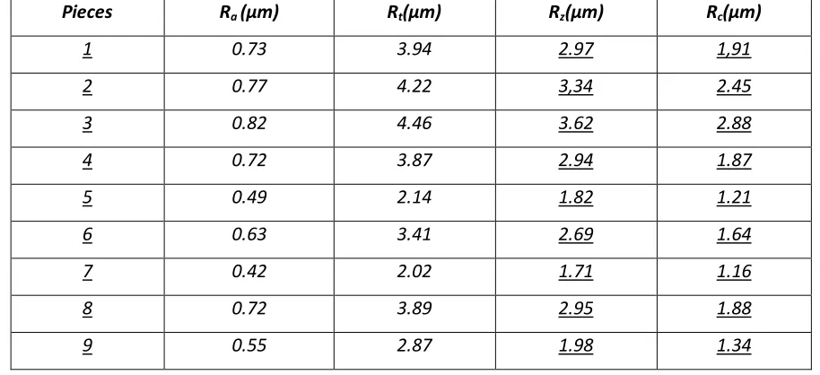
Table 5.2 Measured Roughness Parameters
Pieces Ra (µm) Rt(µm) Rz(µm) Rc(µm)
1 0.73 3.94 2.97 1,91
2 0.77 4.22 3,34 2.45
3 0.82 4.46 3.62 2.88
4 0.72 3.87 2.94 1.87
5 0.49 2.14 1.82 1.21
6 0.63 3.41 2.69 1.64
7 0.42 2.02 1.71 1.16
8 0.72 3.89 2.95 1.88
9 0.55 2.87 1.98 1.34
The main objective of the thesis is to optimize the milling parameters (spindle speed, feed rate, depth of
cut and cutting tool grade) to achieve low value of the surface roughness. The experimental data for the
surface roughness values is shown in Table 5.1.
6.1.2 Optimization by Taguchi Method
Since 1960, Taguchi methods have been used for improving the quality of Japanese products with great
success. During the 1980’s, many companies finally realized that the old methods for ensuring quality
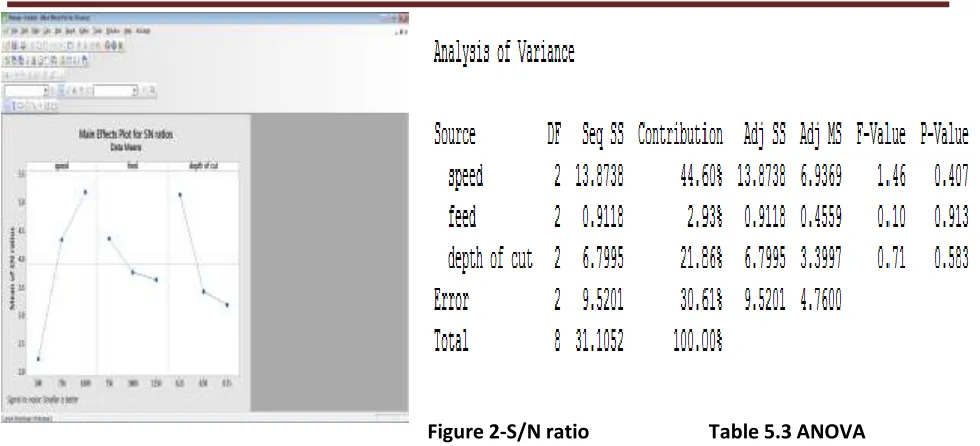
were not competitive with the Japanese methods. Performance characteristics are first converted into
the S/N ratio using the Taguchi method. Using S/N quantity, optimal performance and minimal variance
can be designed. The SR value is calculated for each trial from the basic data collected . The signal
to-noise ratios of each experimental run are calculated based on the following equation, which are listed in
corresponding tables with the data.
𝑆𝑁𝑅 = −10𝑙𝑜𝑔1 𝑛 𝑦
Figure 2-S/N ratio Table 5.3 ANOVA
Table 5.4 Comparison of Taguchi and ANN
Output Comparison of Taguchi Method and ANN Technique
Pieces SR PSR
(Taguchi)
Error
(Taguchi)
Output
(ANN)
Error
(ANN)
1 0.73 0.79 0.06 0.73 0
2 0.77 0.81 0.04 0.77 0
3 0.82 0.71 -0.11 0.75 -0.07
4 0.72 0.61 -0.11 0.62 -0.1
5 0.49 0.55 0.06 0.49 0
6 0.63 0.67 0.04 0.63 0
7 0.42 0.46 0.04 0.42 0
8 0.72 0.61 -0.11 0.72 0
VI. CONCLUSION
1.
The higher the cutting speed, the lower is the surface roughness.2.
The experimental results show that average surface roughness is low at lower depth of cut.3.
For achieving good surface finish on the D2 work piece, higher cutting speed, lower feed andlower depth of cut are preferred. The optimal parametric combination for AISI D2 Steel is
speed3-feed1- depth of cut1.
4.
ANOVA shows that the cutting speed is the most influencing parameter for surfaceroughness.
5.
Mean Absolute Percentage Error is calculated in Taguchi method is 10.77% and MeanAbsolute Percentage is Calculated in MATLAB is 2.90% so ANN technique gives us better
results than Taguchi method .Error is minimized by ANN technique.
6.
Best Model achieved in ANN is with feed forwarded back propagation neural network withLevenberg-Marquardt training function with three layers.
VII. REFERENCES
1. A.Behera, S.Behera, R.K Tripathy, S.C Mishra, “Least Square Support Vector Machine Alternative
To Artificial Neural Network For Prediction Of Surface Roughness And Porosity Of Plasma Sprayed
Copper Substrates”, December, 2012.
2. A.Jameel, M. Minhat, Md. Nizam, “Using Genetic Algorithm to Optimize Machining Parameters in
Turning Operation: A review”, Volume 3, Issue 5, May 2013.
3. A.Joshi & P.Kothiyal, “Investigating Effect of Machining Parameters of CNC Milling on Surface
Finish by Taguchi Method”, Volume-2, Issue-2, 2013.
4. A.K Sahoo, “Application of Taguchi and regression analysis on surface roughness in machining
hardened AISI D2 steel”, International Journal of Industrial Engineering Computations 2014.
5. A.K Gupta, P.Chandna, P.Tandon, “Tool Life Optimization in 2.5d Milling By Coupling Regression
Model And Genetic Algorithm”, International Journal of Engineering and Technology Volume 1 No.
1, October, 2011.
6. A. Aggarwal and H. Singh, “Optimization Of Machining Techniques – A Retrospective and
7. B.C Routara, S.D Mohanty, S.Datta, A. Bandyopadhyay and S.SMahapatra, “Optimization in CNC
end milling of UNS C34000 medium leaded brass with multiple surface roughness characteristics,”
Vol. 35, Part 5, October 2010.
AUTHORS BIOGRAPHIES
ALAMDEEP CHEEMA Passed his diploma in Mechanical engineering In
2008 from haryana state board of technical education and B.tech In 2008 From kurukshetra universitsy
kurukshetra and pursuing M.tech from kuk.
RAJIV KUMAR passed his B.tech from JIET, jind in 2005 and M.tech from GJU Hisar in 2010. Presently he