UNIVERSITI TEKNIKAL MALAYSIA MELAKA
DEVELOPMENT OF WIRELESS VOICE ACTIVATED ROBOT
SYSTEM
This report submitted in accordance with requirement of the Universiti Teknikal
Malaysia Melaka (UTeM) for the Bachelor Degree of Manufacturing Engineering
(Robotics & Automation) (Hons.)
by
MOHD AIDIL BIN OTHMAN B051110274
890421085995
FACULTY OF MANUFACTURING ENGINEERING
DEVELOPMENT OF WIRELESS VOICE ACTIVATED
ROBOT SYSTEM
MOHD AIDIL BIN OTHMAN
B051110274
i
ABSTRAK
Tujuan projek ini adalah untuk membangunkan satu sistem suara robot
diaktifkan tanpa wayar. Teknik panduan yang dicadangkan adalah sistem kawalan
robot mudah alih tanpa wayar yang menggunakan sistem pengenalan suara untuk
mencetuskan dan mengawal pergerakannya. Robot mudah alih bertindak balas
kepada arahan suara dari pengguna untuk melaksanakan apa-apa fungsi pergerakan.
Sistem kawalan suara tanpa wayar yang diaktifkan berkomunikasi dengan
menggunakan dua peranti tanpa wayar yang dibahagikan kepada unit pemancar tanpa
wayar dan unit penerima tanpa wayar. Dengan melaksanakan sistem itu, pengguna
boleh mengendalikan robot mudah alih dengan hanya bercakap melalui mikrofon
tanpa wayar. Fungsi pergerakan robot mudah alih termasuk depan dan belakang,
belok kiri dan ke kanan, dan berhenti. Pengguna perlu melatih perkataan yang
dituturkan bagi memastikan pemproses pengenalan boleh mengenali perkataan yang
dituturkan. Perlaksanaan unit pengenalan suara untuk mencetuskan dan mengawal
pergerakan robot dapat menggantikan kaedah navigasi konvensional. Robot dapat
melakukan pergerakan yang dikehendaki ketika menjawab arahan suara dari
pengguna melalui mikrofon yang mengurangkan keperluan aktiviti tangan. Sistem
pengecaman suara telah direka sebagai perseorangan dan boleh digunakan oleh
seorang pengguna sahaja. Keputusan daripada satu siri ujian telah membuat
kesimpulan bahawa sistem pengawal suara diaktifkan tanpa wayar adalah kaedah
navigasi yang boleh dipercayai. Analisis fungsi keseluruhan menunjukkan prestasi
ii
ABSTRACT
The purpose of this project is to develop a wireless voice activated robot
system. The proposed guidance technique is a wireless mobile robot control system
which employs a voice recognition system for triggering and controlling all its
movements. The mobile robot responds to the voice command from its user to
perform any movements functions. The wireless voice activated controller system is
communicating using two wireless devices which are divided into wireless
transmitter unit and wireless receiver unit. The wireless transmitter unit was a
combination between a microphone, a voice recognition unit, a microcontroller unit
and a wireless module; while the wireless receiver unit was a combination between
another one microcontroller unit and a wireless module. By implementing the
system, the users are able to operate the mobile robot by simply speak through the
wireless microphone. The movement functions of the mobile robot includes forward
and reverse, turn left and turn right, and stop. The user need to trained the word
spoken out in order to make sure the recognition processor can recognize the spoken
words. The implementations of voice recognition unit for triggering and controlling
the mobile robot movement can replace the conventional navigation method. The
mobile robot can perform the desired movement when responding to the voice
command from its user through a microphone that reduces the need of hand
activities. The voice recognition system was designed to be dependent and can be
used by one user only. The results from a series of testing have concluded that the
wireless voice activated controller system is a reliable method of navigation. The
overall function analysis shows the performance of the controller system when
navigating the mobile robot through a path line.
iii
DEDICATION
This report is lovingly dedicated to my respective parent, Othman Bin Burhan and
Chek Gayah Binti Nuri. An appreciation to my Supervisor, Dr. Fairul Azni Bin Jafar,
lecturers and friends that have been my constant source of inspiration. They have
given me the drive and discipline to tackle any task with enthusiasm and
determination. Without their love and support this project would not have been made
iv
ACKNOWLEDGEMENT
All Praise to ALLAH and prayers and peace be upon Muhammad Rasulullah S.A.W.
I would like to acknowledge the contributions of the individuals to the development
of this report. I am also heartily thankful to my supervisor, Dr. Fairul Azni Bin Jafar,
whose encouragement, guidance and support from the initial to the final level
enabled me to develop an understanding of the subject. To my truly great family who
has made available their support in a number of ways. Lastly, I offer my regards and
blessings to all of those who supported me in any respect during the completion of
v
TABLE OF CONTENT
Abstrak i
Abstract ii
Dedication iii
Acknowledgement iv
Table of Content v
List of Tables ix
List of Figures x
List Abbreviations, Symbols and Nomenclatures xiii
CHAPTER 1: INTRODUCTION 1
1.1 Background 1
1.2 Motivation 2
1.3 Problem Statement 3
1.4 Project Objectives 4
1.5 Project Scopes 4
1.6 Report Structure 4
CHAPTER 2: LITERATURE REVIEW 6
2.1 Vehicle Guidance Technology of Mobile Robot 6
2.2 Traditional Navigation of Mobile Robot 8
2.2.1 Wire Guidance 8
2.2.2 Laser Guidance 9
2.2.3 Tape Guidance 10
2.2.4 Inertial Guidance 11
2.2.5 Problem in Navigation of Mobile Robot 12
2.3 Current Navigation Method of Mobile Robot 13
2.3.1 Wi-Fi or Wireless LAN Remote Control 13
2.3.2 Bluetooth 14
2.3.3 3G 16
vi
2.5 Summary 20
CHAPTER 3: METHODOLOGY 21
3.1 Introduction 21
3.2 Overall Method 22
3.3 Design and Planning (Part A) 23
3.3.1 Understanding the System Design and Operation 23
3.3.2 Selection of Hardware and Software 24
3.3.2.1 Microcontroller Unit 24
3.3.2.2 Voice Recognition Unit 26
3.3.2.3 Wireless Transmitter and Receiver Unit 27
3.3.2.4 Arduino IDE Software 29
3.3.2.5 X-CTU Software 29
3.3.2.6 EasyVR Commander Software 29
3.4 Development Process (Part B) 30
3.4.1 Microcontroller Unit Setup and Test 30
3.4.2 Voice Recognition Unit Setup and Test 31
3.4.3 Wireless Transmitter and Receiver Unit Setup and Test 31
3.4.4 Interface All Units 31
3.4.5 Testing 32
3.4.6 Troubleshooting 32
3.5 Analysis and Testing (Part C) 32
3.5.1 Overall Function Test 32
3.5.2 Experimental Design 33
3.5.3 Performance Analysis 34
3.5.4 Troubleshooting 35
3.6 Summary 35
CHAPTER 4: RESULT & DISCUSSION 36
4.1 Design and Planning Result 36
4.1.1 Wireless Transmitter Unit 36
4.1.1.1 Selected Hardware for Wireless Transmitter Unit 37
vii
4.1.2 Wireless Receiver Part 39
4.1.2.1 Selected Hardware for Receiver Part 39
4.1.2.2 Circuit Design for Wireless Receiver Part 41
4.1.3 Selected Software’s 41
4.2 Development Result 43
4.2.1 Arduino UNO Microcontroller Unit Setup and Test Result 43
4.2.1.1 Using Example Code to Blinking “L” LED on 43
Arduino UNO
4.2.2 Voice Recognition Unit Setup and Test Result 47
4.2.2.1 Train EasyVR Voice Recognition Module Using 48
EasyVR Commander
4.2.3 XBee Wireless Unit Setup and Test Result 51
4.2.3.1 XBee Shield Transmitter Module 51
4.2.3.2 XBee Shield Receiver Module 59
4.2.4 Interfacing All Modules 60
4.2.4.1 Wireless Transmitter Module Assembly 61
4.2.4.2 Wireless Receiver Module Assembly 65
4.3 Analysis and Testing Result 66
4.3.1 Preliminary Test 66
4.3.1.1 Result for Preliminary Test 67
4.3.1.2 Analysis for Preliminary Test 67
4.3.2 “Forward and Reverse” Test 69
4.3.2.1 Setup for “Forward and Reverse” Test 70
4.3.2.2 Results for “FORWARD and REVERSE” Test 71
4.3.2.3 Analysis for “FORWARD” and “REVERSE” Test 76
4.3.3 “RIGHT” Turn and “LEFT” Turn Test 77
4.3.3.1 Setup for “RIGHT” Turn and “LEFT” Turn Test 77
4.3.3.2 Results for “RIGHT” Turn and “LEFT” Turn Test 79
4.3.3.3 Analysis for “RIGHT” Turn and “LEFT” Turn 81
4.3.4 Overall Function Test 82
4.3.4.1 Results for Overall Function Test 83
4.3.4.2 Analysis for Overall Function Test 89
viii
4.5 Summary 92
CHAPTER 5: CONCLUSION & FUTURE WORK 93
5.1 Conclusion 93
5.2 Future Work 94
REFERENCES 95
ix
LIST OF TABLES
3.1 Arduino UNO features 25
4.1 Bill of material (BOM) for wireless transmitter unit 37
4.2 Bill of material (BOM) for wireless receiver part 40
4.3 Selected software’s 42
4.4 List of voice commands and its function 50
4.5 Parameter for XBee transmitter module 58
4.6 Parameter for XBee receiver module 59
4.7 Result of voice commands testing 68
4.8 Result of displacement error for “FORWARD” test 76
4.9 Result of displacement error for “REVERSE” test 77
4.10 Degree of turning for “RIGHT” turn test 82
x
LIST OF FIGURE
1.1 An example of Automated Guided Vehicle (AGV) 1
(www.wheelomania.com, 2013).
2.1 Sketch of a basic AGV system using fixed path guidance 6
technology (Kelly et al., 2011).
2.2 The control system of an AGV based on wire guidance. 9
The dotted blue lines represent wire guides mounted in the floor.
Solid blue lines represent information relays (Lindkvist, 1985).
2.3 Rotating laser beam and reflectors determine the AGV path. 10
This new navigation technique has expanded the flexibility of AGV
(Davich T., 2010).
2.4 Front view of SmartCaddy vehicle showing the sensors 11
and floor markings (Rosandich et al., 2002).
2.5 Bridge Connection Pattern WLAN (Feng Cui et al., 2006). 14
2.6 The e-puck robot (Mondada et al., 2009). 15
2.7 System Structure (Jincun et al., 2009). 16
2.8 OTELO Mobile Robotic System (Garawi et al., 2006). 17
2.9 Structure of a standard speech or voice recognition system 18
(http://easi.cc, 2004).
2.10 Example of the RF remote control system 18
(www.projectpiles.com, 2013).
3.1 Mobile robot controller system block diagram. 21
3.2 Overall method for design and development of the controller system 22
3.3 Flowchart of design and planning process for hardware and software
of the controller system 23
3.4 Arduino UNO microcontroller unit (www.gammon.com.au, 2011) 25
3.5 EasyVR Arduino Shield (www.astanadigital.com, 2013) 26
3.6 XBee 1mW Wire Antenna - Series 1 (www.cytron.com.my, 2013) 27
3.7 XBee Shield (without module) (www.cytron.com.my, 2013) 28
3.8 Flowchart of development process 30
xi
4.1 Transmitter circuit design 39
4.2 Receiver circuit design 41
4.3 Interfacing Arduino UNO to a computer 43
4.4 Arduino IDE sketch 44
4.5 Codes examples in Arduino IDE 44
4.6 “Blink” code 45
4.7 Compiling sketch 46
4.8 Uploading sketch 47
4.9 Assembly of EasyVR and Arduino Uno 48
4.10 PC mode 48
4.11 Wordset Command 49
4.12 Group Command 50
4.13 SW mode 51
4.14 XBee module 52
4.15 XBee Shield with XBee module 52
4.16 XBee Shield mounted to Arduino UNO 53
4.17 XBee configure code 54
4.18 X-CTU test 55
4.19 Communication Success 56
4.20 Modem configuration. 57
4.21 Terminal Setup (transmitter) 58
4.22 Terminal Setup (receiver) 60
4.23 Arduino UNO for transmitter 61
4.24 Jumper wire 61
4.25 Jumper wires connected on Arduino UNO 62
4.26 EasyVR Shield mounted on Arduino UNO 62
4.27 Microphone plugged on EasyVR Shield 63
4.28 XBee module mounted on XBee Shield 63
4.29 XBee Shield connected to jumper wires 64
4.30 Complete wireless transmitter module. 64
4.31 Arduino UNO microcontroller board for receiver 65
4.32 XBee module with XBee Shield 65
xii
4.34 Mobile robot platform 69
4.35 “FORWARD” and “REVERSE” test setup 70
4.36 “FORWARD” and “REVERSE” of Test 1 71
4.37 “FORWARD” and “REVERSE” of Test 2 72
4.38 “FORWARD” and “REVERSE” Test 3 73
4.39 “FORWARD” and “REVERSE” of Test 4 74
4.40 “FORWARD” and “REVERSE” of Test 5 75
4.41 Method for measuring displacement error 76
4.42 “RIGHT” turn and “LEFT” turn of test setup 78
4.43 “RIGHT” turn and “LEFT” turn of test 1 and 2 79
4.44 “RIGHT” turn and “LEFT” turn test 3 and 4 80
4.45 “RIGHT” turn and “LEFT” turn of test 5 81
4.46 Method to measures the degree of turning 82
4.47 Navigation experiment setup 83
4.48 Navigation experiment 1 84
4.49 Navigation experiment 2 85
4.50 Navigation experiment 3 86
4.51 Navigation Experiment 4 87
4.52 Navigation Experiment 5 88
xiii
LIST OF ABBREVIATIONS, SYMBOLS AND
NOMENCLATURE
AGV - Automated Guided Vehicle
LED - Light Emitting Diode
3G - Three Generation
FM - Frequency Modulation
RF - Radio Frequency
LGV - Laser Guided Vehicle
AGC - Automated guided carts
IEEE - Institute of Electrical and Electronics Engineers
WLAN - Wireless local area network
PC - Personal computer
PDA - Personal digital assistant
OS - Operating system
MBM - Map based mode
xiv GPS - Global Positioning System
GIS - Geography Information System
IR - Infrared
RFID - Radio-frequency identification
1
This report presents the development and performance analysis of the wireless
voice activated controller system for mobile robot, which is the main project
proposed in this report.
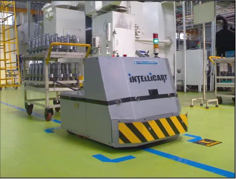
[image:17.595.201.438.408.588.2]1.1 Background
Figure 1.1: An example of mobile robot or Automated Guided Vehicle (AGV) (www.wheelomania.com, 2013).
A mobile robot is manually or automatically controlled by programming the
robot to follow wires in the floor, markers, uses vision or laser as a navigation device
for the robot. They are widely used in industrial applications for transporting
materials around a warehouse or a manufacturing facility.
INTRODUCTION
2
A mobile robot have many advantages compared to other types of material
handling systems, including reliable, flexibility to changes in the material handling
requirements, automatic operation, improved positioning accuracy, easily expandable
layout and system capacity, reduced handling damage, and automated interfaces with
other systems.
The first mobile robot was carried out to market in the 1950s, by Barrett
Electronics of Northbrook, Illinois, where at that time it was simply a tow truck that
navigating to follow a wire in the floor. The technology is now has become more
sophisticated and today automated vehicles are mainly laser navigated, LGV (Laser
Guided Vehicle) (Sharma M., 2012).
A mobile robot uses vehicle guidance technology to define path ways and to
control it movement to follow the pathway. Based on latest technology, there are
some example of guidance technology such as laser guidance system (LGVs), wire
guidance, magnetic guidance, tape guidance or line follower, and etc. The example
of a mobile robot is shown in Figure 1.1.
1.2 Motivation
The rapid growth of technology has introduced the voice recognition system
that has been implemented in many applications. Nowadays, the voice recognition
system became more popular in use as voice based remote control to control various
mobile robot and home appliances.
The wireless voice activated controller system is a new vehicle guidance
technology that has been proposes to improve the mobile robot control. Before this, a
mobile robot uses laser guidance system (LGVs), wire guidance, magnetic guidance,
tape guidance or line follower, and etc. to control its own movement. However, this
guidance system has some disadvantages. For example, the use of line follower
guidance system to follow the tape or paint strips have weaknesses where the tape or
paint strips can easily get dirty or damage when being embedded in high traffic areas.
3
Based on the problem, a new controller system which employs a voice
recognition system is to be designed for triggering and controlling all the mobile
robot movements. The mobile robot responds to the voice command from its user
through a wireless transmission to perform any movement functions. This control
system integrates a microcontroller, voice recognition processor, wireless
communication unit and microphone to control the mobile robot according to the
user command. The user can simply speak to the microphone to operate the mobile
robot from a distance.
1.3 Problem Statement
The first problem is the use of line follower to control the mobile robot by
navigating the mobile robot to follow a tape or paint strips that have a draw back
where the tape or paint strips may become damaged or dirty when the mobile robot is
being embedded in high traffic areas. This may affect the sensitivity of the line
follower sensor to follow the line accurately and may resulting lost track. The line
need to be clean or repaint frequently to maintain the mobile robot movement. With
the presence of the wireless voice activated controller system, the mobile robot can
be control by simply using voice command wirelessly without following any line or
paint strips. The user can choose any available route to navigate the mobile robot to
any location.
Second problem is the use of human body (hand) to operate the conventional
remote controller is an old navigation method that needs a lot of hand activities.
Furthermore, each human has their own capabilities and limitation that makes them
difference with each other’s. This dissimilarity produces difference efficiency
between human in operating the conventional remote control. When operating
conventional remote control, a human need a lot of hand activities to control the
mobile robot efficiently. Thus, it is believed that the mobile robot can be controlled
without any assistance of hand activities when using the wireless voice activated
4
1.4 Project Objectives
To develop a wireless voice activated controller system for a mobile robot.
To analyse the performance of the wireless voice activated controller system.
1.5 Project Scopes
The basic functions of the wireless voice activated controller system for
mobile robot includes, Forward and Reverse Movements, left and right turns,
as well as STOP function.
The mobile robot will be controlled wirelessly through a microphone.
The voice recognition system is designed for speaker dependent (one user)
applications. This means the mobile robot can be controlled by one user only.
If the users change, the system need to be reprogramming based on the new
users voice.
The connectivity range between transmitter and receiver of the wireless voice
activated controller system will not be covered in this project.
The ability of the wireless voice activated controller system to recognize the command word even in the presence of the background noise will not be
discussed in this project.
1.6 Report Structure
This report consists of five chapters.
Chapter 1 shows the introduction of mobile robot and its vehicle guidance
technology, background and brief history, the problem statement of the project,
project objectives and scopes.
Chapter 2 explain the literature review of this project, includes the current and
5
Chapter 3 propose some ideas on how the project will be implemented. The chapter
will lists out the steps and methods involved in each process of the project. This
methodology includes the software and hardware design and explanation on overall
system theory of operation for the development of the wireless voice activated
controller system for the mobile robot.
Chapter 4 provides the result and analysis of data based on system evaluation. It
discusses on how the data are taken in order to analyse the performance of the
wireless voice activated controller system.
Chapter 5 expresses the conclusion of the whole project and gives suggestions for
6
This project is focusing on the development of wireless voice activated
controller system for mobile robot. Section 2.1 of this report will explain the
introduction of vehicle guidance technology of mobile robot, section 2.2 will
explain about traditional navigation method and problem in navigation of mobile
robot; section 2.3 will explain about the current navigation method of mobile
robot, section 2.4 will explain about the propose project of wireless voice
recognition based remote control for mobile robot, and lastly, section 2.5
summary of this chapter.
[image:22.595.200.476.506.655.2]2.1 Vehicle Guidance Technology of Mobile Robot
Figure 2.1: Sketch of a basic mobile robot system using fixed path guidance technology (Kelly et al., 2011).
LITERATURE REVIEW
7
K. Anitha et al. (2013) states that Vehicle Guidance Technology (VGT)
shows the path ways and guide vehicles to follow the pathway.
AGV guidance systems have been growing for about 50 years. Kelly et al.
(2011) defined that there are three guidance methods that have been popular over the
time. Wire guidance is one of the guidance technologies which use wires embedded
in the floor that are sensed inductively to determine vehicle position with the help of
the wire. This in an oldest technology that is not used much today. Other guidance
technology is inertial guidance that uses gyroscope and wheel odometer
(measurement of distance travelled). This navigation technique is used to implement
very accurate dead reckoning. Magnets are placed in the floor at regular intervals to
be used to reset the unavoidable drift of the dead reckoning system. Laser guidance is
the latest guidance technology that uses a spinning laser emitter- receiver that is
mounted on the vehicle. It sense the bearings to retro reflective landmarks placed
accurately in the facility and then it triangulates an accurate solution. Examples of
fixed path guidance technology include rail tracks, embedded wires or other type of
guide-ways (see Figure 2.1).
Today modern AGV systems do not use fixed guide-paths. The guide-paths
may be computer-programmed and transferred to the vehicle’s controllers. These
vehicles are free-ranging and can find their path using optical (laser), magnetic,
odometer, gyroscope, vision, or radio- frequency techniques (Tompskins et al.,
2003).
An issue problem in the guide-path design is selecting a suitable type of
guide-path system, but a guideline to select an appropriate guide-path system is not
available yet. The conventional guide-path system can be seen regularly in
warehouses and distribution centres (Koster et al., 2004).
AGV navigation methods include tape guide path, wire guide path, optical
guide path, and off-wire guidance. In the wire navigation technique, wires with
varying frequencies are buried in the floor. AGV choosing a path at a control point
by referring to the assigned frequency. In the optical navigation technique, an AGV
focuses a beam of light on a reflective tape or a painted strip and follows the path by
8
2.2 Traditional Navigation of Mobile Robot
The guidance technique can be selected based on the type of mobile robot
selected, its application, requirement and environmental limitation. Some of the
significant guidance techniques include:
2.2.1 Wire Guidance
In wire navigation, a wired sensor is placed on the bottom of the AGV by
facing to the ground. Then, a slot is cut in the ground approximately about 1 inch
below the ground to place an energized wire. A radio frequency will be transmitted
from the rooted wire and allows the sensor to detect the wire and then follows the
path. This guidance technique is an earlier technology which is not used much today
(Kelly et al.,2011).
Davich T. (2010), states that the key to an AGV lies within the guidance
system. Methods in tracks or floor markings, such as painted lines or glued on
reflective tape, can be used as a guidance system for AGV. The method that cause
permanent track is not desirable and continuous wear on markings can cause system
reliability issues.
Clayton (1983) explained in detail the methods of wire guidance. Firstly, the
suitable route for the automated guided vehicles is selected and a groove
approximately 2mm/3mm wide and 15 to 20mm deep is cut by using a circular disc
cutter. Then, a plastic coated copper wire is place inside the groove and grouted in. A
high frequency transmitter will feed the wire with a 10 KHz alternating current
which produces a magnetic field that measured by the AGVs controller and then
defined its route instructions. The control system for an AGV based on wire