IJISET - International Journal of Innovative Science, Engineering & Technology, Vol. 2 Issue 4, April 2015. www.ijiset.com
ISSN 2348 – 7968
1015
Reduction in charging current of Super capacitor by series
Parallel connection
Er. P. R. Sawarkar
Abstract
High farad values of Ultra Capacitors (UC) are associated with very large current during charging. This paper proposes proper switching for re-configuration within ultra capacitor bank for reducing charging current. Proposed scheme is simulated using MATLAB Simulink and results were confirmed by mathematical calculation, which indicate that during charging process using similar re-configuration charging current can be reduced. Proposed work show that charging time can be reduced to 330 sec. from 480 sec. in constant current charging method & it is 31.35% faster. In constant voltage method charging time reduced to 96 sec. from 120 sec. & process is20% faster.
Keywords: Super capacitor, Charging , Energy
exchange
Introduction
An electric double-layer capacitor (EDLC) has relatively very high energy density. It is also known as super-capacitor, super-condenser, pseudo-capacitor, electrochemical double layer capacitor, or ultra capacitor. Compared to normal capacitors of low farad value, the energy density of super capacitors is typically thousand times greater. In comparison with conventional batteries or fuel cells, EDLCs have a much higher pulse power density.
For efficient charging of super capacitors Li et al [1] have reported an application using feedforward boost converter, which eliminates the need to use voltage feedback or current feedback. H. Polbck [2] reported in 1999 that resonant converter-operation at high frequency, (typically 80 kHz), offers a cost effective solution to charging when super capacitor and battery work in coherence, for feeding high power to load. A low cost solution has been suggested by Chen and Lai [3], for designing a charger wherein switch-over takes place from constant current charging to constant voltage charging, by the microcontroller unit. Case of
Large energy capacitor units rated at higher voltage has been dealt with by Jeong et al [4] who claim the charging scheme reported by them to be efficient. While dealing with a unit employing a super capacitor and a fuel cell, Kotsopoulos et al dealt with small stand alone system [5]. For electric vehicles, motor starting and regenerative braking involve high rates of discharging and charging. Chan Chau and Chan [6] suggested effective charging methods for super capacitors. For efficiency as well as for longer battery life, such hybrid system needs constant current charger and controlled isolation of battery during the process. This has been described by Kim et al [7].
Proposed Scheme
By using series / parallel combinations, charging times are reduced. Charging process become faster. This paper discusses the charging process of super capacitors at constant current and at constant voltage. As a typical case, a bank with four identical UC is dealt with. Although, the proposal can be readily extended to suitably cover different number of units in any other bank of capacitor. The comparison is to be done in two cases:
Charging process
The Charging process is possible in two different modes.
1.Constant Current Charging. 2.Constant Voltage Charging.
In each of these modes, it is found that if the network of capacitor to be charged is reconfigured as suggested in the proposed scheme, the total charging time can be reduced.
1.1 Constant current charging.
Analysis is done under following two methods in constant current charging.
IJISET - International Journal of Innovative Science, Engineering & Technology, Vol. 2 Issue 4, April 2015. www.ijiset.com
ISSN 2348 – 7968
1016 1.1.1 Without Reconfiguration
Let single equivalent capacitor of 20 F or four identical capacitor of 5F is connected for charging on constant current source of 0.5 Amp 12V. Time required for increase in voltage from 0V to12 V will be Tseconds.
CV
Q
(1)
idt
C
1
C
Q
V(t)
(2)
T0
0.5dt 20
1
12 (3)
s
480
T
(4) Time required to increase the voltage of 20 Fcapacitor from 0Vto 12V without reconfiguration will be 480 seconds with constant current source.
1.1.2 With reconfiguration
Reconfiguration of capacitors will be performed in three actions.
1. Action 1:- All the four uncharged capacitors will be in series up to capacitor voltage reaches to 12V.
2. Action 2:- All four partially charged capacitor from action 1 will be reconnected like, two capacitors will be in series and such two combinations will be in parallel and connected to source up to capacitor voltage reaches to 12V.
3. Action 3:-All partially charge capacitor from action 2 will be reconnected in parallel and charged through the source up to capacitor voltage reaches to 12V.
Action 1
Four uncharged capacitors are connected in series Ceq= (5F)/4=1.25F. Considering 0.5 amp constant
current for charging. Time required for increasing voltage from 0V to 12V is to be calculated as follows. Initial voltage across the capacitor after second action (Vi)=0V (5)
0.5dt 1.25
1 V 12
1 T
0
i
(6)
s
30
T
1
(7)Time required for increasing the voltage of series connected capacitor from 0V to 12V is 30 s.
Action 2
Two partially charged capacitors are connected in series and such two combinations are connected in parallel. Charging will start from Vi = 6V till the voltage reaches 12 V. Here, Ceq= 5 F. Consider 0.5
amp as the constant current for charging. Time required for increasing voltage from 6V to 12V is to be calculated as follows. Initial voltage across the capacitor after second action. . (Vi)=6V (8)
2T
0
0.5dt
5
1
6
12
(9)s
60
T
2
(10)Time required for increasing the voltage of series parallel connected capacitor from 6V to 12V is 60 s.
Action 3
Four partially charged capacitors are connected in parallel. Charging will start from Vi = 6V till the voltage reaches 12 V. Here Ceq= 20 F. Considering 0.5 amp constant current for charging. Time required for increasing voltage from 6V to 12V is to be calculated as follows.
Initial voltage across the capacitor after second action (Vi)=6V (11)
T3
0
0.5dt 20
1 6
12 (12)
s 40 2
T3 (13) Time required for increasing the voltage of parallel connected capacitor from 6V to 12V is 240 s. Total times required in all the three actions will be as follows.
T=T1+T2+T3=30+60+240=330s. (14)
3.1.3 Comparison of charging time in constant current charging method
Comparison of charging time in both the cases i.e. with and without reconfiguration in constant current charging method.
Time consumed in without reconfiguration = 480 s. from eq. (4)
Time consumed in with reconfiguration = 330 s. from eq. (14) From above calculations, it is seen that time saving in percentage for charging with constant current source will be as follows.
[1-(330/480)]×100 = 31.35%, faster. (15) Charging of capacitor will be 31.35 % faster in case of constant current source method with series parallel reconfiguration.
1.2 Constant voltage charging
Analysis is done under following two methods in constant current charging.
1. id co re sh vo cu
R
R
T
Ti ca be 1. th re so A in F. Ti w &In
R
R
V
V
V
V
V
Th ca.2.1Without r
Let single e dentical capac onstant voltag esistance for a hould supply oltage from urrent limiting
Vuc
-(12
R
1.5
20
RC
4(RC)
T
ime required apacitor from e 120 seconds
.2.2With reco
Reconfigurat hree actions econfiguration ource will con
Action1
In action 1 fo n series equiv
. Considering ime required will be T1 and c & R can
voltage
nitial
Vuc
-(12
R
6
1.25
RC
12[1
V(t)
7.58
V(7.5)
10.37
V(15)
11.
V(22.5)
11.78
V(30)
he total vo apacitor with
IJISET - Intern
reconfigurat
equivalent ca citor of 5F is ge source of a limit of 2 A
8 Amp. Tim 0V to12 V w g resistance w
1.5
Ω
c)/8
s
30
5
s
120
d to increas 0Vto 12V w s with constanonfiguration
tion of capac s same as n in constant nstant voltage
our uncharged valent capacit g 2 amp charg
for increasin current limiti n be ca
capa
across
e
6
Ω
c)/2
s
7.5
6
]
e
(t/RC)
85V
76V
.40V
8V
oltage acros time is graphational Journal of
tion
apacitor of 2 connected for 12V with cur Amp per cap me required fo will be as fo will be R.
se the voltag
ithout reconfi nt voltage sou
itors will be s performed t current sour e source.
d capacitors a tance (Ceq) = ging current p g voltage fro ng resistance alculated a
be
will
acitor
s the serie hically shownInnovative Scienc w
20 F or four r charging on rrent limiting pacitor source or increase in follows. The
(16)
(17)
(18)
ge of 20 F figuration will urce. performed in d in with rce. But now are connected = 5 F/ 4=1.25 per capacitor m 0V to 12V will be R. T1 as follows
0V
(Vuc)
e
(19) (20) (21) (22) (23) (24) (25) es connected in Fig.1 ce, Engineering & www.ijiset.com r n g e n e F l n h w d 5 . V 1 . ) d Figu acro duri From 15 se this, will acro (10.3 T1 = Volt Whe and total seco Acti In conn conn (Ceq capa capa and conn actio from resis Initia after VucR
RC
Vol
V(t
V(8
V(1
V(2
V(3
Th conn Fig.2 Technology, Vol. ure. 1 Grap oss the serie ing action 1 m Fig 1 better ec. total volta change in vo be very less. ss series conn 37/12)×100=8 15 s tage per capac en four capac charged thro l voltage acr onds from eq. ion 2: action 2 tw nected in se nected in par q) = 5 F. Con acitor, so sour acitor after fi voltage acr nected capaci on 2. Time r m 5.18V to 12 stance R. T2 & al voltage ac r action 1 = 5.185V5.185)
-(12
8
1.7
5
C
differen
ltage
6
5.18
t)
9.49V
8.5)
11.07V
17)
11.66
25.5)
11.80V
30)
he total vol nected capacit 2 2 Issue 4, April 2 ph for varia es connected r time for chan age across the oltage with re Percentage o nected capaci 86.41 % citor = (10.37 citors of 5F a ough a consta ross the strin (21). wo partially eries, and su rallel. Then nsidering 2 am rce should sup irst action w ross the bra itor will be required for 2V will be T & R can be ca cross two seri1.7
Ω
)/4
s
8.5
5.
-(12
nce
e
6.82[1
(V
6V
V
tage across tor with time 015. ISS ation of tota d capacitor nge over is id e string is 10. espect to chan of total voltag tor is given b 7/4) = 2.59V are connected ant voltage so ng will be 10 charged capa uch two bra equivalent c mp charging c pply 4 amp. V will be (10.37 anch the t (2.59+2.59)= increasing th T2 and. Curre lculated as fo ies connected6.81
.185)
]
t/RC) the series is graphically N 2348 – 7968 1017 al voltage with time dentified as 37V. After nge in time ge build up below. (26)(27)
(28)
d in series ource. The 0.37 at 15 acitors are anches are capacitance current per Voltage per 7/4)=2.59V two series =5.18V for he voltage nt limiting ollows. d capacitor (29) (30) (31)
5V
(32)Fi ac tim as co vo le co (1 T2 V co pa th ac (3 A co (C ca ca =5 ca fo T3 ca af
R
R
VV
V
V
V
V
Th caigure. 2 Gr cross the ser me during ac
From Fig 2 b s 25.5 sec. t onnected capa oltage with r
ss. Percentag onnected capa 11.66/12)×100
2 = 25.5 s Voltage per cap
When two p onnected in arallel. This s hrough a cons cross the strin 33).
Action 3
In action 3 onnected in p Ceq) =20F. C apacitor, so so apacitor afte
5.83V and vo apacitors for or increasing 3 and. Curren alculated as f fter action 2 (
5.83
-(12
R
0.7
20
RC
differe Voltage
5.83
V(t)
9.51V
V(16)
10.92
V(32)
11.42
V(48)
11.62
V(64)
he total vo apacitor with
IJISET - Intern
raph for va ies/parallel c ction 2
better time fo total voltage
acitor is 11.6 espect to cha ge of total vol
acitor is given 0=97.16 %
pacitor = (11. partially char series and tw series / parall stant voltage ng will be 11
four partial parallel. Now Considering 2
ource should er second a oltage across t action 3 will the voltage fr nt limiting res follows. Initia Vuc) = 5.83V
0.771
Ω
3)/8
s
15.42
717
(12 ence e
6.17[1
V
2V
2V
2V
ltage across time is graphational Journal of
ariation of t connected ca
r change over across the s 66V. After th ange in time
tage build up n below.
.66/2) =5.83V rged capacito
wo such bra lel combinatio
source. The 1.66 after 25
lly charge ca w, equivalent
amp chargin supply 8 amp ction will b the parallel co l be 5.83V. T from 5.83V to sistance R. T al voltage acr V.
Ω
s
6.1 5.83) - ]
e
(t/RC)the paralle hically shown Innovative Scienc w total voltage apacitor with
r is identified series/parallel his, change in will be very p across series
(38)
(39)
V (40)
ors of 5F are anches are in on is charged total voltage .5 s from eq apacitors are t capacitance ng current per p. Voltage per be (11.66/2) onnected four Time required o 12V will be 3 & R can be ross capacitor (41)
(42)
(43)
17V (44)
(45) (46) (47) (48) (49) el connected in Fig.3 ce, Engineering & www.ijiset.com e h d l n y s ) e n d e . e e r r ) r d e e r d Figu acro actio Fr as 4 capa with Perc conn (11.6 T3 = Whe para cons capa (45). From Tota follo T=T Vari show Figu reco 1.2.3 volta Co the cons with Technology, Vol. ure. 3 Grap oss the conn on 3 om Fig 3 bett 8 sec. total v acitor is 11.6 h respect to centage of to nected capacit 62/12)×100=9 64 s en four parti llel this paral stant voltage acitor will be . m eq. (21), eq al time require ows. T1+T2+T3=15+ iation of volta wn in Fig. 4 ure. 4 Vo onfiguration 3Comparison age charging omparison of cases i.e. w stant voltage c hout reconfigu 2 Issue 4, April 2 ph for varia nected capaci ter time for c voltage across 62V. After th change in ti otal voltage tor is given b 96.83% ially charged llel combinati source. The e 11.62 after q. (33), eq. (45 ed in all three +17+64=96s. age per capac oltage per n of charging g method f charging tim with and with charging met uration = 120 015. ISS ation of tota itor with tim change over is s the parallel his, change ime will be build up acr elow. d capacitors ion is charged total voltage r 64 seconds 5) e actions will itor is graphic capacitor g time in con me of capacit hout reconfig hod. Time co s. from eq. (1 N 2348 – 7968 1018 al voltage me during s identified connected in voltage very less. ross series (50) (51)
of 5F are d through a across the s from eq. be as (51) cally
in with
nstant
tor in both guration in onsumed in
18)
IJISET - International Journal of Innovative Science, Engineering & Technology, Vol. 2 Issue 4, April 2015. www.ijiset.com
ISSN 2348 – 7968
1019
Time consumed in with reconfiguration = 96 s. from eq. (51). From above calculations, it is seen that time saving in percentage for charging with constant voltage source will be as follows.
[1-(96/120)]×100 = 20%, faster. (52) Charging of capacitor will be 20 % faster in case of constant voltage source method with series parallel reconfiguration.
1.3 Simulation results of charging action using MATLAB
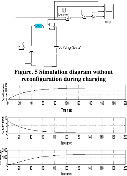
The circuit parameters used for simulation in MATLAB / Simulink environment is given below. Simulation work is done only in constant voltage method. This is explaining below. Configuration parameter for simulation is Solver is ode25tb, Variable stapes, Non adaptive algorithm. Simulation is done for constant voltage source method. Voltage Source of 12 V, Capacitor is of 5F, Ideal switches, static range block are the components of simulation. The Simulation model and its output response when reconfiguration of circuit is not done are shown in fig. 5Fig. 6 shows the response of simulation of without reconfiguration during charging. Fig. 7 shows the simulation of with reconfiguration during charging. Fig. 8 Response of simulation of with reconfiguration during charging
Figure. 5 Simulation diagram without reconfiguration during charging
Figure. 6 Response of simulation of without reconfiguration during charging
Figure. 7 Simulation of with reconfiguration during charging
Figure. 8 Response of simulation of with reconfiguration during charging
6. Conclusions
Series / parallel reconnections lead to faster processes during exchange of energy in case of capacitor banks. The proposed scheme also helps to reduce the rating of charging circuit. It deserves attention for applying to industrial system. In industrial applications for ride-through applications in drives, and applications as short duration UPS, super capacitor banks are used. It is necessary work on prototypes’, to conclude the quantitative advantages of the proposed scheme, when implemented for real life strategic applications.
7. References
IJISET - International Journal of Innovative Science, Engineering & Technology, Vol. 2 Issue 4, April 2015. www.ijiset.com
ISSN 2348 – 7968
1020
Conference on System Science and Engineering, Macau, China, 8-10 June 2011 ICSSE 2011 p.p. 65-69.
[2] Helen Pollock, “High efficiency, high frequency power supplies for capacitor and battery charging,” published by the IEE, Savoy Place, London WCPR OBL,IEE 1999, p.p. 9/1-9/10 [3] Bo-Yuan Chen, Yen-Shin Lai, “New
Digital-Controlled Technique for Battery Charger With Constant Current and Voltage Control Without Current Feedback,” IEEE transactions on industrial electronics, March 2012,vol,59.3,p.p. 1545-1553.
[4] In-Wha Jeong , long-Soo Kim, Gennadi I. Guse. and Geun-Hie Rim, “Design of 35kJ/s 25kV Capacitor Charging Power Supply for Pulsed Power Systems,” IEEE Conference of the IEEE Industrial Electronics Society Busan, Korea, November 2 - 6,2004,Vol 3, p.p. 2860-2863. [5] MarcoS. W. Chan , K. T. Chau , and C. C. Chan,
“Effective Charging Method for Ultra capacitors” Journal of Asian Electric vehicles, Volume 3, Number 2, December 2005,Vol 3, Number 2, p.p. 771-776.
[6] Donghwa Shin, Younghyun, Kim, Jaeam Seo, and Naehyuck Chang, “Battery-Super capacitor Hybrid System for High-Rate Pulsed Load Applications”, EDAA, 14-18 march 2011, p.p. 1-4.
[7] A. Kotsopoulos, J.L. Duarte, and M.A.M. Hendlix, “A Converter to Interface Ultra-
Capacitor Energy Storage to a Fuel Cell System”, Dept of Electrical Engineering, Technical University of Eindhoven. The Netherlands , IEEE,4-7 may,2004,Vol 2, p.p.827-832.
[8] P.R. Sawarkar, S.G. Tarnekar , S.B. Bodkhe ,“ Improvement in Energy Transactions in Ultra Capacitor Banks by Series/Parallel