INFLUENCE OF TIME AND TEMPERATURE ON RESISTIVITY AND MICROSTRUCTURE OF CuxCo1−xFe2O4 MIXED FERRITES
B. K. Bammannavar, L. R. Naik, and R. B. Pujar
Department of Physics Karnatak University Dharwad 580003, India
B. K. Chougule
Department of Physics Shivaji University Kolhapur 416004, India
Abstract—Copper-cobalt ferrites with generalchemicalformula CuxCo1−xFe2O4 (with x = 0.0, 0.4, 0.6 & 1.0) were prepared by ceramic method. The solid state reaction was confirmed by XRD patterns. DC conductivity was measured by two probe method. Electrical resistivity is found to increase on lowering of sintering temperature and time. At x = 1.0, the conduction is mainly due to hopping of electrons leading to n-type conductivity while at x = 0.0, conduction is due to holes leading to P-type conductivity. The lowest conduction at x = 0.4 is attributed to the electron hole compensation. SEM micrographs were obtained from JEOL scanning electron microscope. The micrographs reveal that an average grain size increases with sintering temperature and time as a result of decrease in porosity. This leads to the decrease in resistivity with sintering temperature and time. One of the factors for higher conductivity in ferrites is an increase in average grain size and decrease in pore concentration during the heat treatment.
1. INTRODUCTION
122 Bammannavar et al.
influences the dielectric [3–7] and magnetic behavior of ferrites [8, 9]. This created considerable interest in many research workers for the development and potential applications of ferrites in the electronic industry [10–12]. Now a days the study of ferrites has occupied an important place in the electronics technology [13]. The practical applications of ferrites are now of immense service in every day life, as electronic and magnetic ceramics. Because of their poor electrical conductivity [14], they have revolutionized the field of high and ultrahigh frequency electronics with negligible eddy current losses. This is the reason why ferrites have occupied a unique position in this field.
Many parameters play an important role in determining a particular application of material. The quantities such as magnetization, coercivity, permittivity [15], conductivity etc. are greatly influenced by porosity, grain size and microstructure of the sample [16, 17]. Ferrites containing Cobalt and Copper exhibit several interesting properties which make them suitable for switching and memory devices. At frequencies above 50 MHz cobalt is preferred to preclude magnetic losses [18]. Cobalt is invariably doped to various ferrites for the rapid relaxation to lattice [19]. In this paper we report the influence of composition and heat treatment on resistivity and microstructure of CuxCo1−xFe2O4 ferrites.
2. EXPERIMENTAL DETAILS:
Figure 1. Variation of resistivity with temperature.
3. RESULTS AND DISCUSSION:
The variation of resistivity as a function of temperature is shown in Figure 1. The change in slope is markedly observed in all the samples, such change is either due to Curie temperature [20] or due to change in conduction mechanism [21]. This indicates the semiconducting nature of ferrites. The resistivity in ferrites obeys the relation
ρ=ρoexp (∆E/KT)
124 Bammannavar et al.
energy in the ferromagnetic region is attributed to the phase transition or impurity phases, while the change in activation energy is attributed to the change in conduction mechanism [22].
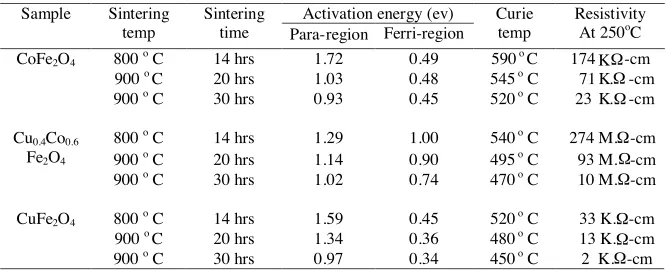
Table 1. Data on sintering temp/time, activation energy, Curie temperature and resistivity.
Activation energy (ev) Sample Sintering
temp
Sintering
time Para-region Ferri-region
Curie temp
Resistivity At 250o
C 800o C 14 hrs 1.72 0.49 590 oC 174 K -cm 900oC 20 hrs 1.03 0.48 545 o C 71 K. -cm CoFe2O4
900o C 30 hrs 0.93 0.45 520 o C 23 K. -cm 800o
C 14 hrs 1.29 1.00 540 o
C 274 M. -cm 900o
C 20 hrs 1.14 0.90 495 o
C 93 M. -cm Cu0.4Co0.6
Fe2O4
900o
C 30 hrs 1.02 0.74 470 o
C 10 M. -cm
800o C 14 hrs 1.59 0.45 520 o C 33 K. -cm 900oC 20 hrs 1.34 0.36 480 o C 13 K. -cm CuFe2O4
900o C 30 hrs 0.97 0.34 450 o C 2 K. -cm
Ω Ω Ω Ω Ω Ω Ω Ω Ω
The change in activation energy for different compositions is attributed to the hoping of polarons. The values of activation energy above 0.2 eV clearly indicate the polaron hopping in the system [23]. The addition of cobalt replaces Fe3+ ions from B site which intern replaces Cu2+ ions in A site. There fore the presence of cobalt on B site favors the conduction mechanism in Cu-Co ferrites by polaron hopping [23].
Co2++ Fe3+⇔Co3++ Fe2+
In CuFe2O4 Ferrite, Fe2+ concentration is appreciable and conduction is due to hopping of electrons from Fe2+ → Fe3+ leading to n-type conductivity with relatively low activation energy. Low conductivity in CoFe2O4 is due to deficiency of iron leading to P-type conductivity with relatively large activation energy (Table 1). The lowest conduction in Cu0.4Co0.6Fe2O4 with largest activation energy is attributed to electron-hole compensation. The decrease in Curie temperature with increase in sintering temp/time is attributed to the decrease in A-B interactions [24].
(a) (b)
(c) (d)
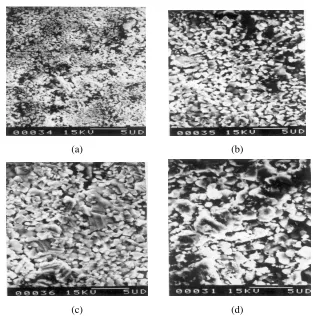
Figure 2. SEM micrographs of CuxCo1−xFe2O4 at different sintering temperature/time. (a) x = 0 sintered at 800◦C for 14 hrs, (b) x = 0 sintered at 900◦C for 20 hrs, (c) x = 0 sintered at 900◦C for 30 hrs, (d)x= 1 sintered at 800◦C for 14 hrs.
treatment the grain size varies upto 10µm. Figure 2(c) shows the maximum grain size in a sample sintered at 900◦C for 30 hrs.
126Bammannavar et al.
the characteristic microstructure of ferrites in which residualporosity appears in intragranular space. This is clearly indicated in the samples (Figures 2(a) to 2(d)).
The close survey of the micrographs revels that the samples sintered at 800◦C for 20 hrs contain large number of small grains with more porosity than the samples of same composition sintered at 900◦C for 20 hrs. The micrographs also represent two typical microstructures that cover entire field of magneto ceramics. One type has a high density containing large grains (Figure 2(c)) more than 10µm and remaining porosity is present as clouds of fine spherical pores inside the crystallites. Such microstructure may due to oxygen vacancies as a result of reduction during firing. Another type consists of smaller and pore free crystallites (Figures 2(a) & 2(d)) however the large pores are present at the boundaries of crystallites. Such structure is due to the certain amount of metalion vacancies caused by oxidation or suitable doping. These results are in good agreement with those reported for Ni-Zn ferrites [26].
It can be seen from the micrographs that the average grain size increases with increase in temperature/time with decrease in porosity [27]. This results higher conductivity in the samples as a consequence of decrease in resistivity [28]. The presence of air gaps between the grains result in the formation of inhomogeneous dielectric structure. This greatly affects the DC and AC resistivity of ferrites and hence conduction mechanism in ferrites is largely dependent on porosity. Therefore smaller the porosity greater will be the grain size and higher will be the conductivity. The micrographs indicate the low porosity in a matrix of large sized grains in ferrites sintered at higher temperature for a longer time. This causes decrease in resistivity and increase in conductivity. Therefore it can be emphasized that one of the factor for higher conductivity in ferrites is the increase in average grain size and decrease in pore concentration during the heat treatment.
4. CONCLUSION
ACKNOWLEDGMENT
One of the author (BKB) thanks to University Grant Commission (UGC), New Delhi, (India) for awarding Junior Research Fellowship under RFSMS scheme.
REFERENCES
1. Koledintseva, M. Y. and A. A. Kitaitsev, “Analysis of interaction between crystelographically uniaxial ferrite resonators and a Hall-effect transducer,” Progress In Electromagnetics Research, PIER 74, 1–19, 2007.
2. Lagarkov, A. L., V. N. Kisel, and U. N. semenenko, “Wide-angle absorption by use of a metamaterial plate,” Progress In Electromagnetics Research Letters, Vol. 1, 35–44, 2008.
3. Kumar, A. and S. Sharma, “Measurement of dielectric constant and loss factoe of the dielectric material at microwave frequencies,”Progress In Electromagnetics Research, PIER 69, 47– 54, 2007.
4. Kkalaj-Amirhosseini, M., “Microwave filters using waveguides filled by multilayer dielectric,” Progress In Electromagnetics Research, PIER 66, 105–110, 2006.
5. Soliman, E. A. and G. A. E. Vandenbosch, “Greens functions of filament sources embedded in stratified dielectric media,”Progress In Electromagnetics Research, PIER 62, 21–40, 2006.
6. Nikellis, K., N. Uzunoglu, Y Koutsoyannopoulos, and S. Ban-tas, “Full-wave modeling of stripline structures in multilayer dielctrics,”Progress In Electromagnetics Research, PIER 57, 253– 264, 2006.
7. Saed, M. and R. Y. Yadla, “Microstrip-fed low profile and compact dielectric resonator antennas,” Progress In Electromagnetics Research, PIER 56, 151–162, 2006.
8. Fu, Y. P., K. Y. Pan, and C. H. Lin, “Ni-Cu-Zn ferrite powder from steel pickled liquor and electroplating waste solutions,” Mater. Lett., Vol. 57, 291–296, 2002.
9. Singhal, S., J. Singh, S. K. Barthwal, and K. Chandra, “Preparation and characterization of nanosized nickelsubstituted cobalt ferrite,”J. Solid. State. Chem., Vol. 178, 3183–3189, 2005. 10. Afrang, S. and B. Y. Majlis, “Small size KA-band distributed MEMS phase shifters using inductors,” Progress In Electromag-netics Research B, Vol. 1, 95–113, 2008.
128 Bammannavar et al.
negative refractive index metamaterials: Analysis and experi-ment,”Progress In Electromagnetics Research, PIER 64, 205–218, 2006.
12. Wongkasem, N., A. Akyurtlu, and K. A. Marx, “Group theory based design of isotropic negative refractive index metamaterials,” Progress In Electromagnetics Research, PIER 63, 295–310, 2006. 13. Rahman, I. Z. and T. T. Ahmed, “A study on copper substituted
chemically processed Ni-Zn-Cu ferrites,”J. Magn. Magn. Mater., Vol. 290, 290–291, 2005.
14. Tosyulu, O. S., J. Gowri Krishna, and J. Sobhanandri, “A method for the evaluation of dielectric parameters of solids at microwave frequencies,”J. Phys. E: Scientific Instruments, Vol. 59, 323–327, 1982.
15. He, X., Z. Tang, B. Zhang, and Y. Wu, “A new deem bedding method in permittivity measurement of ferroelectric thin film material,” Progress In Electromagnetics Research Letters, Vol. 3, 1–8, 2008.
16. Chinnasamy, C. N., A. Narayanasamy, N. Ponpandian, K. Cat-topadhyay, H. Gueralt, and J. M. Greneche, “Magnetic properties of nanostructured ferromagnetic zinc ferrites,”J. Phys. Condens. Matter., Vol. 12, 7795–7799, 2000.
17. Nathani, H., S. Gubbala, and R. D. K. Misra, “Magnetic behaviour of nanocrystalline nickel ferrite part I: The effect of surface roughness,”Mater. Sci. Engg., Vol. 121(B), 291–296, 2005. 18. Sivakumar, N., A. Narayanasamy, and N. Ponpandian, “Grain size effect on the dielectric behavior of nanostructured Ni0.5Zn0.5Fe2O4,”J. Apply. Phy., Vol. 101, 084116–0841122, 2007. 19. Von Aulock, W. H.,Hand Book of Microwave Ferrites, Academic
Press, NY, 1965.
20. Ravinder, D. and B. Ravikumar, “A study on elastic behaviour of rare earth substituted Mn-Zn ferrites,” Mater. Lett., Vol. 57, 4471–4473, 2003.
21. Krishnamurthy, K. R., Ph.D. Thesis, Indian Institute of Technology, Madras, India, 1975.
22. Pujar, R. B., S. N. Kulakarni, and B. K. Chougule, “Compo-sitional, temperature and frequency dependence of initial per-meability in Zr4+ substituted Mg-Zn ferrites,” Mater. Sci. Lett., Vol. 15, 1605–1608, 1996.
Mater., Vol. 307, 222–226, 2006.
24. Radhakrishana, S. and K. V. S. Badrinath, “Studies on the ferroelectric-parelectric transition of dicalcium lead propnate,”J. Matt. Sci. Lett., Vol. 3, 575–577, 1984.
25. Verma, A., T. C. Goel, R. G. Mrndirratta, and P. Kishan, “Magnetic properties of nickel-zinc ferrites prepared by the citrate precursor method,”J. Magn. Magn. Mater., Vol. 208, 13–19, 2000. 26. Smit, J., Magnetic Properties of Materials, McGraw Hill Book
Company, NY, 1971.