Integration of Wind and Wave Power Generation to a DC
Micro Grid Using Fuzzy Controller
B. KARTHIK
1T. KARTHIK
21
PG Scholar, Dept of EEE(EPS), Brilliant Group of Technical Institutions.Hyderabad,, TS, India.
2Assistant Professor, Dept of EEE, Brilliant Group of Technical Institutions.Hyderabad, TS, India.
ABSTRACT
This paper presents analysis of power flow management in wind power and wave power. This paper proposed an integrated wind and wave power generation system fed to an ac power grid or connected with an isolated load using a dc microgrid using FUZZY controller. The proposed dc microgrid connects with a wind power generator through a voltage -source converter (VSC), a wave power generator through a VSC, an energy storage battery through a bidirectional dc/dc converter, a resistive dc load through a load dc/dc converter, and an ac power grid through a bidirectional grid - tied inverter. The studied integrated wind and wave system joined with the dc microgrid is modeled and simulated using MATLAB/Simulink model design reveals that the proposed integrated control system can maintain stable operation to supply power under different operating conditions using the proposed dc microgrid by varying duty ratios of individual converter and pitch angle of wind system is shown.
Keyword:
- W ind power, W ave power, fuzzycontrol, Battery s torage, Micro grid
1.
INTRODUCTION
Renewable energy and distributed generation systems (DGSs) have attracted increasing attention and have been extens ively researched and developed. They gradually alter the concepts and operations of conventional power generation s ys tems . The rise in several countries makes it possible that this kind of DGS can be practically applied to a grid-tied system or an isolated system with wind power, solar energy, hydropower, etc. The output of DGS usually includes two kinds: dc and variable ac. Moreover, the generating capacity of DGS comparing with conventional large synchronous generators is much smaller, and hence, the dc microgrid can be practically applied to convert the generated
time-varying quantities of natural renewable energy and DGS into smooth dc electricity that can then be converted back into ac quantities delivered to other power systems [1], [2]. Because of the intermittence of renewable energy and DGS, bidirectional dc/dc converters are usually necessary to feed the connected loads with smooth power [3].
In order to simulate a hybrid ac/dc microgrid system, photovoltaic and wind power generator models, a doubly fed induction generator model, and an inverter model were established to simulate the dynamic responses of the studied system in [4]. A practical low-voltage bipolar-type dc microgrid was constructed using a gas engine as the power source, while a bidirectional dc/dc converter shunting a super capacitor was utilized as an energy storage device to balance the power demand of the studied system in [5]. Unexplored energy and resources in ocean such as marine energy, tidal energy, ocean thermal energy, ocean wave energy, salinity gradient energy, etc., are abundant. The simulated results of an Archimedes wave swing (AWS) power convertor coupling with a linear permanent magnet generator (LPMG) were simulated using MATLAB/Simulink. A configuration of a marine power plant with two AWSs connecting to a power grid was proposed in [7], and the outputs of the two AWSs were converted to dc quantity by individual diode bridge rectifiers and then subsequently converted into ac quantity by an inverter to reduce the fluctuation of the combined rectified output power.
to reduce simulation computational intensity. A non isolated bidirectional zero -voltage switching dc/dc converter was proposed in [9], and the converter utilized a very simple auxiliary circuit consisting of an additional winding of a main inductor and an auxiliary inductor to reach zero voltage switching and reduce the reverse -recovery problem of power diodes.
Modeling and testing the data centers of a dc microgrid using MATLAB were proposed in [10] an d [11] since most data centers were sensitive to the variations of electronic loads. The proposed dc microgrid was also used to supply sensitive electronic loads during ac grid outages in order
to offer uninterruptible power system protection [11]. To achieve power sharing and improve economic benefit, a dc bus voltage control technique for parallel integrated permanent magnet wind power generation systems was proposed in [12], and the technique was based on a master–slave control to solve controller discrepancy problems. In order to achieve power sharing and to optimize the dc microgrid, the control strategies for an islanded microgrid with a dc-link voltage control were developed in [13] and [14], while the control strategies were combined with P/V droop control and constant- power band to avoid frequent changes and voltage-limit violation on generation devices
.
Fig -1: Co nfiguration o f th e studied integrated wind and wave p ower generation s ystem co nnected to a p ower g rid th ro u g h th e p ro p o s ed d c micro g rid .
A battery/ultra capacitor hybrid energy storage system was proposed in [15] for electric -drive vehicles. To satisfy the peak power demands between the ultra capacitor and battery, a larger dc/dc converter was necessary. The studied system utilized two storage devices to compensate mutually in order to prolong the life of the battery. The s imulated and experimental res ults were carried out to verify the propos ed control s ys tem. This paper propos es an integrated wind and wave power generation system fed to a power system or connected with an isolated load using a dc microgrid. A bidirectional dc/dc converter is proposed to achieve the integration of both wind and wave power generation systems
with uncertainty and intermittent characteristics.
2.
DESIGN OF A WIND TURBINE
GENERATING SYSTEMS
Mainly, three types of induction generators are used in wind power conversion s ys tems : cage rotor, wound rotor with slip control and doubly fed induction rotors. The last one is the most utilized in wind speed generation because it provides a wide range of speed variation. However, the variable-speed directly-driven multi-pole permanent magnet synchronous generator (PMSG) wind architecture is chosen for this purpose and it is going to be modeled: it offers better performance due to higher efficiency and less maintenance because it does not have rotor current. What is more, PMSG can be used without a gearbox, which implies a reduction of the weight of the nacelle and reduction of costs. System Modeling
Topology of non-grid-connected wind energy conversion system this paper discussed is shown in Fig.1. PMSG that with PWM voltage source vector control which can enable a high energy efficiency by adjusting the rotational speed, is directly driven by a fixed pitch wind turbine, DC bus voltage is constant under the control of Boost converter which ensures the power balance of the system, Buck converter is introduced to maintain the output voltage a constant. The basic control strategy is to achieve maximum peak power tracking of wind turbine while operating in below rated power condition and to limit the power while operating in the above rated power condition.
Fig -2: To p o lo g y o f n o n g rid co n n ected win d en erg y co n v ers io n s y s tem
2.2 W ind Turbine 1. Generator Model
Fig -3: Ho rizo n tal axis win d mill The wind systems that exist over the earth‟ s
surface are a result of variations in air pressure. These are in turn due to the variations in solar heating. Warm air rises and cooler air rushes in to take its place. Wind is merely the movement of air from one place to another. There are global wind patterns related to large scale solar heating of different regions of the earth‟ s surface and seasonal variations in solar incidence. There are also localized wind patterns due the effects of
temperature differences between land and seas, or mountains and valleys. Wind speed generally increases with height above ground. This is because the roughness of ground features such as vegetation and houses cause the wind to be slowed.
………… (1)
Cp value is calculated in the next subsystem by using the following formula:
………… (2)
J: Inertia moment of the turbine, axle and generator F: Axle friction
Tem: Electromagnetic torque
Wind speed data can be obtained from wind maps or from the meteorology office. Unfortunately the general availability and reliability of wind speed data is extremely poor in many regions of the world. However, significant areas of the world have meant annual wind speeds of above 4-5 m/s (meters per second) which makes small-scale wind powered electricity generation an attractive option. It is important to obtain accurate windspeed data for the site in mind before any decision can be
made as to its suitability. Methods for assessing the mean wind speed are found in the relevant texts (see the „References and resources‟ section at the end of this fact sheet).
The power in the wind is proportional to: •The area of windmill being swept by the wind
•The cube of the wind speed
•The air density - which varies with altitude
The formula used for calculating the power in the wind is shown below:
Where, P is power in watts (W)
ρ is the air density in kilograms per cubic metre (kg/m3) A is the swept rotor area in square metres (m2)
V is the windspeed in metres per second (m/s)
The fact that the power is proportional to the cube of the wind speed is very significant. This ca n be demonstrated by pointing out that if the wind speed doubles then the power in the wind increases by a factor of eight. It is therefore worthwhile finding a site which has a relatively high mean wind speed.
2.3Fixed - Pitch W in d Tu rb in e Model
The kinetic energy of the wind (air mass m, wind speed v) is given by the following equation:
With:
(With S: Covered surface of the turbine and p: the air density)
………… (5)
The mechanical power that the turbine extracts from the windis inferior to. This is due to the fact that the wind speed after the turbine isn‟ t zero (the air needs to be carried off after the turbine.
3. MODELLING OF THE PROPOSED SYSTEM
3.1 Ov erv iew o f Sy s tem Co n fig u ratio n
Fig. 1 shows the configuration of the studied integrated wind and wave power generation system connected to an ac grid through a dc microgrid. The wind power generation system simulated by a permanent-magnet synchronous generator (PMSG) driven by a wind turbine (WT) is connected to the dc microgrid through a VSC of VSC_PMSG.
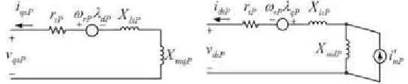
Fig -4: q -d axis eq u iv alen t circu it mo d el o f th e s tu d ied win d PM SG The wave power generation system simulated by
an LPMG driven by a linear permanent magnet motor (LPMM) is also connected to the dc microgrid through a VSC of VSC_LPMG. A resistive dc load R-Load is connected to the dc microgrid through a load dc/dc converter. To achieve stable power flow (or power balance condition) and load demand control of the dc microgrid under different operating conditions, a battery is connected to the dc microgrid through a bidirectional dc/dc converter, while an ac grid is connected to the dc microgrid through a bidirectional grid-tied inverter and a transmission line. When available wind power and/or wave power can be injected into the dc microgrid with a fully charged battery, the surplus power of the dc microgrid can be delivered to the ac grid through the bidirectional grid-tied inverter. When no wind power or no wave power is delivered to the dc microgrid with a low-energy battery, the insufficient power of the dc microgrid can be captured from the ac grid through the bidirectional grid-tied inverter.
The power of the resistive dc load R-Load can be obtained from the dc microgrid through the load dc/dc converter only when the dc microgrid has enough power. The load dc/dc converter with the resistive dc load R-Load can also slightly adjust the power balance condition of the dc microgrid.
The control functions of the bidirectional dc/dc converter, the bidirectional grid-tied inverter, and the load dc/dc converter must be adequately coordinated with each other to obtain stable operation of the dc microgrid. In this thesis, the mathematical models of the studied integrated system with the proposed dc microgrid are derived in detail, including the wind WT -PMSG set with its VSC, the wave LPMM-LPMG set with its VSC, the bidirectional dc/dc converter with the battery, the load dc/dc converter with the resistive load, and the bidirectional grid -tied inverter. Both frequency-domain analysis and time-domain simulations are performed using MATLAB/Simulink.
4.
EQUIVALENT MODELS
4.1Eq u iv alen t M o d els o f W t an d Pms g
The WT model employed in this paper includes the following operation conditions: the cut -in wind speed of 4 m/s, the rated wind speed of 13 m/s, and the cut-out wind speed of 24 m/s. The detailed characteristics an d expres s ions for the captured mechanical power Pw, the dimensionless power coefficient Cpw, the mechanical torque
studied wind PMSG. The per-unit (p.u.) q- and d -axis stator winding voltages of the studied PMSG can be expres s ed by equation as follows are the q- and d-axis stator-winding magnetic fluxes , respectively
iqsP and idsP are the q- and d-axis stator-winding
currents, respectively; XmqP and XmdP are the q-
and d-axis magnetizing reactance‟ s, respectively; XlsP is the leakage reactance; XmP is the
magnetizing current; rsP is the stator winding equivalent resistance; and ωrP is the rotor speed of the studied PMSG, while p is the differential operator with respect to time t (i.e., p = d/dt), and ωb is the base angular speed in radians per second.
4.2Eq u iv alen t M o d els Of Aws A n d Lpmg
The AWS utilizes the wave swing to drive the generator to produce electric power without transmission medium. The motion of the AWS in fluid is affected by the damping force and spring force. The equivalent mass -spring- damper model of the studied AWS is illustrated, whose motion equations can be described by
where m is the sum of the masses of the floater and the LPMG translator; D and S are the damping coefficient and spring constant, respectively; and
Fwave, z, and u are the floater driving force,
distance traveled by the floater, and speed of the floater of the AWS, respectively [18]–[21]. Fig. 4.2 draws the q–d-axis equivalent circuit model of an LPMG. The nonlinear p.u. differential equations of the LPMG can be written as
where idsg and iqsg are the d- and q-axis equivalent magnetizing currents, respectively;
Xmg is the magnetizing current; Xlsg is the equivalent leakage reactance; Rsg is the equivalent internal resistance; Xmqd and Xmdg are the q- and d-axis magnetizing inductance, respectively; and Xd = Xlsg + Xmdg and Xq = Xlsg + Xmqg
of the studied LPMG, while K = π/τp, τp is the electrode distance, and us is the forcer movement speed of the LPMG.
Fig -5: q–d-axis equivalent circuit model o f the studied LPMG.
4.3DESIGN OF CONTROL BLOCKS OF PM SG’S VSC
Fig. 4.3 illustrates the control block diagrams of the indices mq1 and md1 of the studied PMSG‟ s VSC. The d- and q-axis reference currents are generated by comparing the output active power of the PMSG (PPMSG) with its reference value using maximum power point tracking function. After subtracting the output currents of the PMSG (ig_PMSG) from their respective reference values, the resultant differences pass through the respective first -order lag controllers to obtain the deviations of the respective modulation indices that are added to their respective initial values to acquire the VSC‟s modulation indices. The limiters, namely,md1_max,md1_min,mq1_max, andmq1_min, are included in the model to ensure normal operation of the VSC.
4.4CONTROL BLOCKS OF LM SG’S VSC
Fig. 4.4 plots the control block diagrams of the indices mq3 and md3 of the studied LPMG‟s VSC. After subtracting the output currents of the LPMG (ig_LMSG) from their respective reference values, the resultant differences pass through the respective proportional-integral controllers to obtain the deviations of the respective modulation indices which are added to their respective initial values to obtain the VSC‟s modulation indices. The limiters, namely, md3_max, md3_min,
mq3_max, and mq3_min, are included in the model to ensure normal operation of the VSC.
4.5CONTROL BLOCKS OF BIDIRECTIONA L GRID-TIED INVERTER
Fig. 4.5 draws the control block diagram of the modulation indices mq2 and md2 of the grid-tied voltage-source inverter (VSI). The grid-tied VSI is required to feed the generated power of the renewable-energy systems to the power grid.
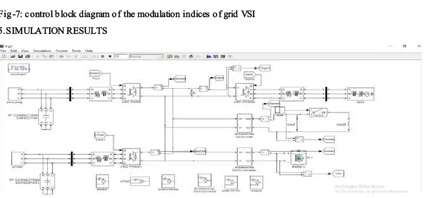
Fig -7: control b lock diagram o f the modulation indices o f grid VSI 5.SIMULATION RESULTS
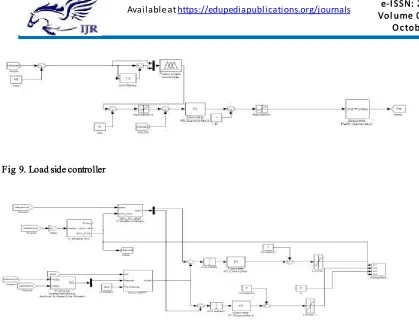
Fig 9. Load side controller
Fig 10. PMSG controller
Fig 11. Out put voltage of PMSG
Fig 13. Out put voltage of the wind LPMG
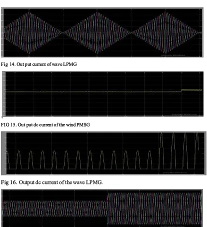
Fig 14. Out put current of wave LPMG
.
FIG 15. Out put dc current of the wind PMSG
Fig 16.
Output dc current of the wave LPMG.
CONLUSION
An integration of both wind power and wave power generation systems joined with a dc microgrid has been proposed. A laboratory-grade test system has been presented in this paper to examine the fundamental operating characteristics of the studied integrated system fed to isolated loads using a dc microgrid. For simulation parts, the results of the root-loci plot and the time-domain responses have revealed that the studied integrated system with the proposed dc microgrid can maintain stable operation under a sudden load -switching condition. Comparative simulated and measured results under a load switching have been performed, and it shows that the stud ied integrated system with the proposed dc microgrid can be operated stably under different disturbance conditions, while both measured and simulated results can match with each other.In extension we using fuzzy controller for better accuracy and observed by output results.
REFERENCES
[1] Y. Ito, Y. Zhongqing, and H. Akagi, “DC microgrid based distribution power generation system,” in Proc. 4th IEEE Int. Power Electron. Motion Control Conf., 2004, vol. 3, pp. 1740–1745. [2] S. K. Kim, J. H. Jeon, C. H. Cho, J. B. Ahn, and S. H. Kwon, “Dynamic modeling and control of a grid-connected hybrid generation system with versatile power transfer,” IEEE Trans. Ind. Electron., vol. 55, no. 4, pp. 1677–1688, Apr. 2008. [3] C. Abbey and G. Joos, “Supercapacitor energy storage for wind energy applications,” IEEE Trans. Ind. Appl., vol. 43, no. 3, pp. 769–776, May 2007. [4] X. Liu, P. Wang, and P. C. Loh, “A hybrid ac/dc microgrid and its coordination control,” IEEE Trans. Smart Grid, vol. 2, no. 2, pp. 278–286, Jun. 2011. [5] H. Kakigano, Y. Miura, and T. Ise, “Low-voltage bipolar-type dc microgrid for super high quality distribution,” IEEE Trans. Power Electron., vol. 25,
no. 12, pp. 3066–3075, Dec. 2010.
[6] M. G. D. S. Prado, F. Gardner, M. Damen, and H. Polinder, “Modeling and test results of the Archimedes wave swing,” J. Power Energy, vol. 220, no. 8, pp. 855–868, Dec. 2006
B. KA RTHIK has received his B.Tech degree in
Elecrical and Electronics Engineering from TKR
COLLEGE OF ENGGINEERING AND
TECHNOLOGY ,JNTUH. and M.Tech in Electrical
Power Systems from
BRIG-JNTUH,Hyderabad,TS,India.