Wind Speed Estimation Based Sensorless Output
Control for A Wind Turbine Driving A DFIG
UNagaraju #1, Dr. L Maheswari*2
#
M. Tech student, GATES Institute of Technology, Gooty, Andhrapradesh, India
*
Professor, Dept. of EEE
GATES Institute of Technology, Gooty, Andhrapradesh, India
ABSTRACT
A specific design of the proposed control algorithm for a wind turbine equipped with a doubly fed induction generator (DFIG) is presented. The aerodynamic characteristics of the wind turbine are approximated by a Gaussian radial basis function network based nonlinear input-output mapping. Based on this nonlinear mapping, the wind speed is estimated from the measured generator electrical output power while taking into account the power losses in the WTG and the dynamics of the WTG shaft system. The new control methodology means the fuzzy logic controller has been developed and evaluated in detail. Finally, the proposed method is applied to the wind generation system The estimated wind speed is then used to determine the optimal DFIG rotor speed command for maximum wind power extraction. The DFIG speed controller is suitably designed to effectively damp the low-frequency torsional oscillations. The resulting WTG system delivers maximum electrical power to the grid with high efficiency and high reliability without mechanical anemometers.
I. INTRODUCTION
PERMANENT-MAGNET generators (PMGs) are commonly used in small and medium-size wind turbine systems for electrical power generation [1], [2]. Compared to the wind turbines equipped with induction generators, there are several advantages of using PMGs. First, the PMGs can provide high-efficiency and high-reliability power generation, since there is no need for external excitation and no copper losses in the rotor circuit. Second, the high-power-density PMGs are small in size, which reduces the cost and weight of the wind turbine generator (WTG) system. Moreover, the wind turbine equipped with a direct-drive PMG removes the need of using a gearbox. According to the statistical data reported in [3], about 19.4% downtime of WTGs is caused by failures of gearboxes. Without gearboxes, the WTG systems need less maintenance and have a reduced downtime and a higher reliability. Control, monitoring, and protection of WTGs usually require the information of wind speed and generator rotor position/ speed, which can be measured by well-calibrated mechanical sensors, such as anemometers and rotor position sensors, respectively. However, the use of these mechanical
of the PMG. Second, a model adaptive reference system (MRAS) observer is designed to estimate the rotating speed of the PMG by using the estimated back EMF from the sliding-mode observer. Third, based on the measured electrical power and estimated rotor speed of the PMG, the mechanical power of the wind turbine is estimated by taking into account the power losses of the system. Fourth, the wind speed is estimated with the information of the WTG shaft speed and mechanical power by using a back-propagation artificial neural network (BPANN). The estimated wind speed is then used to determine the optimal shaft speed reference. Based on the proposed estimation algorithms, a sensorless control is developed for PMG wind turbines to continuously generate the maximum electrical power without using any wind speed or rotor position sensors.
II. MODELLING OF THE WIND
ENERGY CONVERSION
SYSTEM
In this, various design and modelling aspects of different components of the Wind Energy Conversion System like the basic models of synchronous generator, AC-DC-AC PWM converter, wind turbine, drive train and their control system are described
Fig 1 Proposed Wind Energy Conversion System The proposed WECS system consists of wind turbine, two mass drive train, permanent magnet synchronous machine (PMSM) which is torque controlled and AC-DC-AC PWM converter.
Permanent Magnet Synchronous Generator (PMSG)
The PMSG is a Synchronous Machine, where the DC excitation circuit is replaced by permanent magnets, by eliminating the brushes. PMSG has a smaller physical size, a low moment of inertia which means a higher reliability and power density per volume ratio as it has permanent magnets instead of brushes and the slip rings. Also by having permanent magnets in the rotor circuit, the electrical losses in the rotor are eliminated. The PMSG are becoming an interesting solution for wind turbine applications [1]. However, the disadvantages of the permanent magnet excitation are high costs for permanent magnet materials and a fixed excitation, which cannot be changed according to the operational point. The PMSG can be classified according to the rotor configuration: Interior magnet type (IPMSG) for this
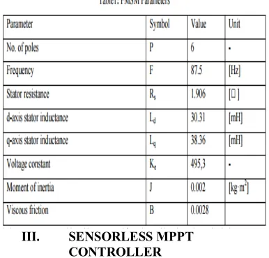
configuration, the magnets is buried inside the rotor. The interior magnet PMSG usually presents magnetic saliency. The d-axis inductance is smaller than the q-axis inductance (Ld<Lq), because the effective air gap of the d-axis is bigger than the q-axis air gap. This results in a component of reluctance torque in addition to the torque produced by the magnet. Because of this, the rotor position is much easier to detect. Surface mounted magnet type (SPMSG) The SPMSG has the magnets mounted on the surface of the rotor. As the permeability of the permanent magnets is approximately equal to 1, permanent magnets act like air in magnetic circuits. This means that the air gap is very large and constant. The d- and q-axis inductances are nearly identical and the saliency ratio (= Lq/Ld) is 1. Therefore no reluctance torque occurs. One advantage of the SPMSG is that the surface mounted magnets lead to a very simple rotor design with a low weight. The parameters of the machine are presented in Table 1
III. SENSORLESS MPPT
CONTROLLER
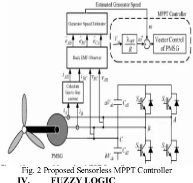
proportional to the speed of the generator. Knowing the number of rotor poles and measuring the time between two rising zero crossings (one complete cycle) of the generated voltage the speed of the generator is found out. Once the time taken for one cycle of the generated voltage is found, the corresponding frequency of the generated voltage can be obtained. Hence, the speed of the generator is given by
Fig. 2 Proposed Sensorless MPPT Controller
IV. FUZZY LOGIC
In recent years, the number and variety of applications of fuzzy logic have increased significantly. The applications range from consumer products such as cameras, camcorders, washing machines, and microwave ovens to industrial process control, medical instrumentation, decision-support systems, and portfolio selection. To understand why use of fuzzy logic has grown, you must first understand what is meant by fuzzy logic.
Fig.3 the Primary GUI Tools Of The Fuzzy Logic Toolbox The FIS Editor handles the high level issues for the system How much input and output variables? What are their names? The Fuzzy Logic Toolbox doesn't limit the number of inputs. However, the number of inputs may be limited by the available memory of our machine. If the number of inputs is too large, or the number of membership functions is too big, then it may also be difficult to analyze the FIS using the other GUI tools.The Membership Function Editor is used to define the shapes of all
the membership functions associated with each variable. The Rule Editor is for editing the list of rules that defines the behavior of the system.
4.1.The FIS Editor
The following discussion walks we through building a new fuzzy inference system from scratch. If we want to save time and follow along quickly, we can load the already built system by typing fuzzy tipper This will load the FIS associated with the file tipper.fis (the .fis is implied) and launch the FIS Editor. However, if we load the pre-built system, we will not be building rules and constructing membership functions.
Fig.4 The FIS Editor
We will see the diagram updated to reflect the new names of the input and output variables. There is now a new variable in the workspace called tipper that contains all the information about this system. By saving to the workspace with a new name, we also rename the entire system. Our window will look like as shown in Fig.5.
Fig.5 The Updated FIS Editor
4.2 The Membership Function Editor
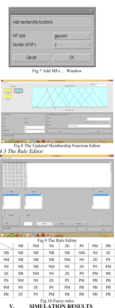
Fig.7 Add MFs… Window
Fig.8 The Updated Membership Function Editor
4.3 The Rule Editor
Fig.9 The Rule Editor
Fig.10 Fuzzy rules
V. SIMULATION RESULTS
In this section, simulation results are presented to verify the validity of operations of the proposed system under steady- state and transient conditions. The simulated system parameters are listed in Table T. These simulations were performed using control systems mentioned in Section IV. The variable frequency mode of six switch AC/AC converter is selected since two three phase terminals of the converter work with different frequency
Fig 11 Simulink model of proposed system
A. Operation of Constant Wind Speed
Fig 12 Dc link voltage
Fig 13 the grid voltage and the input current
Fig 14 power delivered to the grid and extracted mechanical power
Fig. 15Injected three phase currents to the Grid
B. Operation of Variable Wind Speed
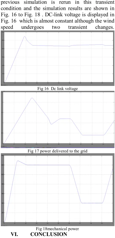
In order to examine the proposed system performance under the transient condition, wind speed has been varied from 13 mls to 9 mls in t=0.6 sec and then from 9 mls to 11 mls in t=0.9 sec. The
previous simulation is rerun in this transient condition and the simulation results are shown in Fig. 16 to Fig. 18 . DC-link voltage is displayed in Fig. 16 which is almost constant although the wind speed undergoes two transient changes.
Fig 16 Dc link voltage
Fig 17 power delivered to the grid
Fig 18mechanical power
VI. CONCLUSION
In this paper the fuzzy control of wind energy conversion system in order to get constant output power is obtained and verified through the simulation. The main goal of implementing fuzzy controller is to continuously adapt the constant power of the generator and the wind speed in a way that the turbine operates at its optimum. The advantages of using fuzzy controller are verified by its simulation results, fast response, and parameter insensitivity. Implemented system has satisfactory, dynamic and static performance.
REFERENCE
[1] H. Karimi-Davijani,1A. Sheikholeslami, H. Livani and M. KarimiDavijani,” Fuzzy Logic Control of Doubly Fed Induction Generator Wind Turbine”, World Applied Sciences Journal 6 (4): 499-508, 2009, IDOSI Publications, 2009
Operating in Weak-Grid Systems” IEEE Transactions On Power Electronics, September 2009.
[4] Wei Qiao, Wei Zhou, José M. Aller, and Ronald G. Harley, Fellow, IEEE “Wind Speed Estimation Based Sensorless Output Maximization Control for a Wind Turbine Driving a DFIG” IEEE transactions on power electronics, may 2008.
[5] Yuanye Xia, Khaled H. Ahmed, and Barry W. Williams “A New Maximum Power Point Tracking Technique for Permanent Magnet Synchronous Generator Based Wind Energy Conversion System” IEEE transactions on power Electronics, vol. 26, no. 12, december 2011
[6] D.Aouzellag ,K.Ghedamsi,, E.M.Berkouk “ Power Control of a Variable Speed Wind Turbine Driving an DFIG” Electrical engineering Department, A.Mira University, Bejaïa, Algeria. [7] Y¨uksel O˘GUZ1, ˙Irfan GUNEY2 “Adaptive neuro-fuzzy inference system to improve the power quality of variable-speed wind power generation system” Turk J ElecEng& Comp Sci, Vol.18, No.4, 2010, _c TU¨BI˙TAK.
[8] EvgenijeAdzic*, ZoranIvanovic*, Milan Adzic**, Vladimir Katic “Maximum Power Search in Wind Turbine Based on Fuzzy Logic Control” ActaPolytechnicaHungarica Vol. 6, No. 1, 2009.