Review of Analysis of Flow around a heat radiators to
determine suitable shape of vortex generators
Pramod Rakt Patel; Neeraj Gehlot; Eshan Srivastava & Tushar Singh
1,2
Assistant Professor Mechanical departmentSRM UNIVERSITY, NCR CAMPUS
3,4
UG Student Mechanical EngineeringSRM UNIVERSITY, NCR CAMPUS
Abstract
The paper presents an analysis of flow around a radiator’s components to determine the relative effect of vortex generators around the components. The corresponding graphs of related turbulent kinetic energy are plotted to show mixing of different layers of fluid. The analysis is performed by using RANS method. The performed tasks give a greater understanding of the physical fluid flow around the vortex generator.
1.
Introduction
It is known beyond doubt that a constant approach towards making the locomotives more economical is on its way. The need for smaller and more efficient parts is the need of the hour. Moreover a more efficient heat exchanger permits the user for relatively cheaper engine coolants. Certain sections of the heat radiator are analyzed, with different vortex generators on their surface. . The second compares the rise in the temperature of the fluid flowing inside the radiators. The models used are developed in the PRO-E, and analyzed in ANSYS.
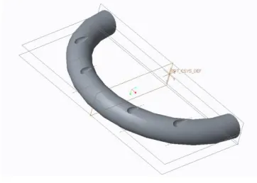
The above figure shows the areas under considerations ,these areas considered separately for understanding the effect vortex generator on the on the flow around these.
2. Modelling Procedure
Outer diameter-7mm (~ approximate diameter for heat radiators used in the heavy locomotives).
Fig 2.1 Cylinder with delta vg Fig 2.2 Plain cylinder
Fig 2.3 Cylinder with dent type vg
Fig 2.4 Bent Pipe with dent type vg Fig 2.5 Simple bent pipe
Fig 2.6 Bent type pipe with vortex gnerators
2. The geometries imported into ANSYS design modeler and freeze the solid is performed, a
rectangular enclosure is created and solid shape under considerations is subtracted.
Fig 2.7
3. The geometry so created is imported into ANYS meshing and provided with proper names for the
inlet and the outlet of air and the removed solid’s imprint is named as the wall.
4. The following meshing was provided –
a. Relevance-80
i. Relevance center-fine
ii. Transition-High
b. Method –Hex dominant
c. Refining -2, all surfaces.
Fig 2.8
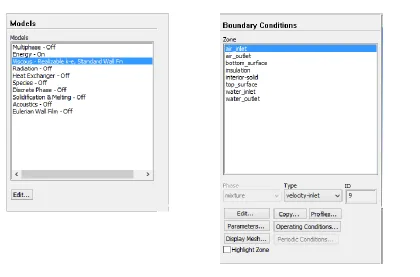
5. The Generated model was imported into FLUENT, where the following boundary conditions
were provided-
a. The following were selected – the material as air and K-epsilon for model with standard wall
realizable functions. Switch on the energy equation.
b. Air inlet velocity-5.5m/s (approximate relative speed of air based on average speed of trucks
on Indian roads).
c. Initialization was done using standard initialization for all sections, and using second order
upwind for turbulent kinetic energy and turbulent kinetic energy.
d. Solution was obtained and graphs for different surfaces so obtained are shown below
Fig 2.9
Fig-3.1-Turbulent Kinetic Energy at inlet vs. outlet for a simple cylinder
Fig-3.2 Turbulent Kinetic energy for cylinder with vortex generator (delta) flow from wedge side
Fig-3.3 Turbulent Kinetic energy for cylinder with vortex generator (delta) flow from Ram side.
The following graphs were obtained. These taking fig 3.1 as the basic figure and comparing the rest of the graphs it can be clearly seen that fig3.4 the output turbulent kinetic energy is significantly higher as compared to the basic cylinder hence it does not help in mixing turbulent layers with the slow moving layers at the surface. Hence not demoting the boundary layer separation. Comparing fig 3.1 with fig 3.2, and 3.3, it can be clearly seen although the temp at the outlet is slightly more than the fig 3.1, the no of particles with lower turbulent kinetic energy is significantly higher indicating a greater mixing of turbulent particles in the flow thus promoting uniform flow around the cylinder, hence increasing the momentum transfer between different particles and delaying the boundary layer separation, promoting a slightly higher rate of heat transfer.
4.Results and discussions
Fig3.5 Turbulent Kinetic energy graph for bent cylinder with no vortex generator
Fig3.7 Turbulent Kinetic energy graph for bent cylinder with vortex generator (delta) flow from ramp side.
Fig3.8 Turbulent Kinetic energy graph for bent cylinder with vortex generator (dent).
For the bent linear pipe we have the following graphs graph comparing the graphs 3.5 with graph 3.6 and 3.7 it can be clearly seen that the output turbulent kinetic energy for wedge side is significantly lower as the fluid flowing from this side encounters larger area of vortex generator and thus provides us with slowest boundary layer separation. The dent type vortex generator provides almost the same turbulent kinetic energy mixing.
Conclusions
From the above graphs it can be concluded that wedge type vortex generators provides with greatest mixing and hence this profile provides maximum momentum transfer, by decreasing local viscosity temporarily, thus promoting the greater transfer by permitting greater number of colder particles to come in contact with the hotter surface.
References
[1] Ronald E Marvin, 1995, “Numerical
[2] Pedro Patricio da Silva and Werner Krauth, 1997, “Numerical Solutions of the von Karman Equations for a Thin Plate”, International Journal of Modern Physics, vol.8 pp 42-53.
[3] Wüest, Alfred, Gabriel Piepke, 2000,
“Turbulent kinetic energy balance as a tool for estimating vertical diffusivity in wind-forced stratified waters”, International Journal of oceanography, vol.45, pp1388-1400
[4] B.R. Bull, May 2003, “A Study of the
Application of Vortex Generators to Enhance the Air-Side Performance of Heat Exchangers” Journal of Air Conditioning and Refrigeration Center, vol.4 pp 1-47
[5] Amol Andhare, V M Kriplani, J P
Modak, December 2014, “Thermal Analysis of
a Helical Coil Heat Exchanger”, International Journal of Innovative Research in Advanced Engineering, vol.1, pp 135-143.
[6] P.T.Griffiths, 2015, “Flow of a
generalised Newtonian fluid due to a rotating disk”, Journal of Non Newtonian Fluid Mechanics, vol.221, pp 9-17.
[7] Si-Yu WANG, Hong-Bin LI, 2015,
“Influence of Crosswind on Aerodynamic Performance of Wind Turbine in Wind-drive Device”, Journal of International Conference on Material Science and Applications, vol 2, pp 1075-1080
[8] Molecular gas dynamics- Oxford