WIDEBAND CO-PLANAR MICROSTRIP PATCH ANTENNA
A. Danideh and R. Sadeghi-Fakhr
Electrical Engineering Department Science & Research Campus Islamic Azad University Tehran, Iran
H. R. Hassani
Electrical & Electronic Engineering Department Shahed University
Tehran, Iran
Abstract—A new antenna structure comprising a semicircular microstrip patch alongside a small rectangular shape ground proximity fed by a microstrip line is proposed. On a thin substrate this antenna achieves in the range of 5.8–12.9 GHz an impedance bandwidth of almost 75%. Details of the antenna design, simulation and measured results on the return loss and theE and H-plane radiation pattern of the proposed antenna are presented.
1. INTRODUCTION
patch with shorting posts [8]. Majority of these works carried out are based on relatively thick substrates. Indeed, there are many different methods proposed in the literature to tackle the narrow-band width problem, [9–11] none of which uses thin substrate to achieve wide bandwidth performance.
In this paper, a low profile microstrip patch antenna is proposed. Unlike the usual method of placing the patch antenna on top of a ground plane, the patch is placed along side a small rectangular ground co planar to it. The thickness of the substrate used is approximately 0.02λ (1.6 mm). The size of the ground and the radius of the patch and their relative position are optimized to achieve a wide bandwidth. The optimized antenna structure achieves in the frequency range of 5.86–12.86 GHz an impedance bandwidth of almost 75%. E and H -plane radiation patterns shows slight tilt in the main beam position but the patterns are almost unchanged in the operating band. The achieved performance has been validated by the measured return loss and radiation patterns.
Figure 1. Geometry of the proposed antenna.
2. ANTENNA GEOMETRY
finite ground plane that has a rectangular shape with size of GW = 30 mm × GL = 10 mm. The dielectric substrate used is FR4 of dimension 30×30 mm2 with thickness h = 1.6 mm. The separation distance between the patch and the ground is d = 2 mm. The patch is proximity fed by a 50 Ω microstrip line with line length and width
F L = 10 mm and F W = 3 mm, respectively. The top and bottom views of the fabricated antenna are shown in Fig. 2.
Figure 2. Top and bottom views of the proposed antenna.
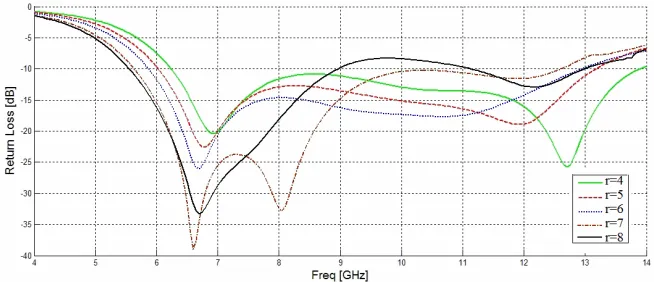
Figure 3. Return loss of the antenna with changes in patch radius,r.
the size of the patch and at the same time maximize the bandwidth it was found that a semicircular patch and an optimized geometry of the whole structure (the ground plane dimension, separation between the patch and the ground and feed line position) gives the best possible impedance bandwidth.
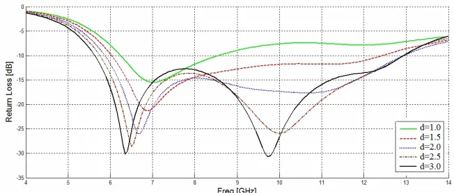
Figure 4. Return loss of the antenna with changes in separation between patch and ground plane, d.
3. SIMULATION AND MEASUREMENT RESULTS
in proximity fed patch antennas the position of the feed line under patch is important. Fig. 7, shows the effect of the feed line length,
F L. ForF L= 10 mm the highest bandwidth with good return loss is noticeable.
Figure 5. Return loss of the antenna with changes in ground plane width, GW.
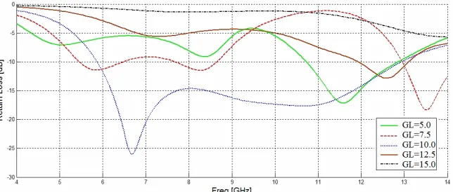
Figure 6. Return loss of the antenna with changes in ground plane length,GL.
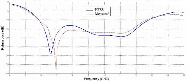
while the measured result shows 73%. As a comparison, the same semicircular patch as that of Fig. 1 with r= 6 mm if placed on top of a grounded dielectric shows a resonance frequency of 12.44 GHz with 6.5% impedance bandwidth.
Figure 7. Return loss of the proposed antenna with changes in feed line length,F L.
Figure 8. Simulated and measured return loss of the proposed antenna with: r = 6 mm, d = 2 mm, GW = 30 mm, GL = 10 mm,
F L= 10 mm, h= 1.6 mm.
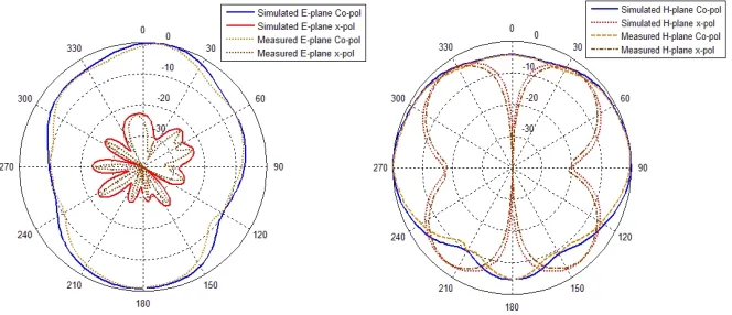
Figures 9 to 11 shows the measured radiation patterns for the
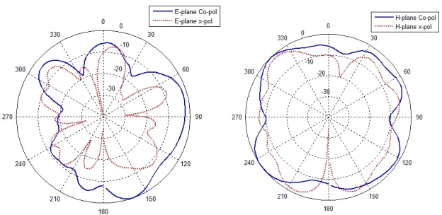
Figure 9. Measured E- andH-plane radiation pattern at 6 GHz. simulated and the measured patterns agree well at all frequencies. The patterns are bi-directional and are almost stable across the impedance bandwidth. The cross polarization level is quite low. The distorted radiation pattern in the higher frequency is caused by the unequal phase distribution on the antenna aperture and increased magnitudes of higher order modes [12].
Figure 11. MeasuredE- and H-plane radiation pattern at 11.5 GHz.
4. CONCLUSION
In this paper a co-planar microstrip patch antenna with wide bandwidth behavior has been proposed. Simulated as well as measured results are presented for a semicircular shape patch antenna. Compared with other microstrip patch antennas of high bandwidths this proposed structure has the attractive features of low profile, smaller patch size and being simple to design. Optimization of the structure gives 73% impedance bandwidth with reasonable bidirectional patterns suitable for many applications.
REFERENCES
1. Kumar, G. and K. C. Gupta, “Directly coupled multiple resonator wide-band microstrip antenna,” IEEE Transactions on Antennas and Propagation, Vol. 33, 588–593, June 1985.
2. Wong, K. L. and Y. F. Lin, “Small broadband rectangular microstrip antenna with chip-resistor loading,” Electron. Lett., Vol. 33, 1593–1594, 1997.
3. Yang, F., X.-X. Zhang, X. Ye, and Y. Rahmat-Samii, “Wide-band E-shaped patch antennas for wireless communications,” IEEE Transactions on Antennas and Propagation, Vol. 49, No. 7, 1094– 1100, July 2001.
antennas,” IEEE Transactions on Antennas and Propagation, Vol. 51, No. 3, 457–468, March 2003.
5. Eldek, A. A., “Numerical analysis of a small ultra wideband microstrip-fed tap monopole antenna,” Progress In Electromag-netics Research, PIER 65, 59–69, 2006.
6. Eldek, A. A., A. Z. Elsherbeni, and C. E. Smith, “Rectangular slot antenna with patch stub for ultra wideband applications and phased array systems,” Progress In Electromagnetics Research, PIER 53, 227–237, 2005.
7. Mehdipour, A., K. Mohammadpour-Aghdam, and R. Faraji-Dana, “Complete dispersion analysis of vivaldi antenna for ultra wideband applications,” Progress In Electromagnetics Research, PIER 77, 85–96, 2007.
8. Row, J. S. and S. H. Chen, “Wideband monopolar square ring patch antenna,” IEEE Transactions on Antennas and Propagation, Vol. 54, No. 4, 1335–1339, April 2006.
9. Joardar, S. and A. B. Bhattacharya, “Two new ultra wideband dual polarized antenna-feeds using planar log periodic antenna and innovative frequency independent reflectors,” Journal of Electromagnetic Waves and Applications, Vol. 20, No. 11, 1465– 1479, 2006.
10. Chen, X. and K. Huang, “Wideband properties of fractal bowtie dipoles,” Journal of Electromagnetic Waves and Applications, Vol. 20, No. 11, 1511–1518, 2006.
11. Chair, R., A. A. Kishk, K. F. Lee, C. E. Smith, and D. Kajfez, “Microstrip line and CPW FED ultra wideband slot antennas with U-shaped tuning stub and reflector,”Progress In Electromagnetics Research, PIER 56, 163–182, 2006.