ISSN (Print) : 2320 – 3765 ISSN (Online): 2278 – 8875
I
nternational
J
ournal of
A
dvanced
R
esearch in
E
lectrical,
E
lectronics and
I
nstrumentation
E
ngineering
(An ISO 3297: 2007 Certified Organization)
Vol. 5, Issue 7, July 2016
Concept of Earthing in Power House &
Switchyard with Operation Analysis of Earth
Fault Controller using ATP Software
Monika Jain1, Abhinaw Pandey2, Aditya Pandey3
Assistant Professor, Dept. of Electrical & Electronics, OIST Engineering College, Bhopal, India1 PG Student [Power System], Dept. of Electrical & Electronics, OIST Engineering College, Bhopal, India 2 PG Student [Power System], Dept. of Electrical & Electronics, OIST Engineering College, Bhopal, India 3
ABSTRACT: In this paper has described the process of Earthing sizing for Switch Yard & Power House with basic
concept of ground grid design, comparison with switch yard & Power house sizing & selection of ground electrodes, soil resistivity measurement with improving methodology of soil resistive to achieve adequate minimum ground resistance. Earthing is to limit the effect of ground potential gradient to such as voltage & current levels that will not endanger the safety of people or equipment under normal and fault conditions. The system shall also ensure continuity of service. The main two following aspect behind earthing are,
- Provide a low-impedance ground to fault current return path in order to activate the protection and clear or alarm the ground fault as soon as possible. Low resistance path will also allow ground fault to flow through the earth conductor instead of person’s.
- Limit the voltages on station structures and accessible equipment both during normal operation and during electrical transients to safe levels.
Another part of in this paper has described function of Earth Fault Controller (EFC) in a faulted phase earthing. Controller is used for reducing customer hours lost (CHL) and customer interruptions (CI) during earth fault in system to operate as an interchangeable high resistance earthed/isolated system in conjunction with FPE.
The proposed system used with Neutral Earth Resistor (NER), which is switched out during sustained faults. Basically natural earth resistor is required to restrict switching over-voltages. Transformer neutral will be isolated during a single line to ground fault in system & faulted phase will be earthed and as the phase to phase voltage is unchanged with the FPE applied, and load is connected via delta windings the supply voltage to customers is maintained. The concept for this controller was initially tested by Ireland Electricity Board. ATP Model is used for analysis of EFC controller operation & characteristic of faulty system.
KEYWORDS: Grounding Grid, Faulted Phase Earthing (FPE), Neutral Earth Resistor (NER) Continuity Supply, Line
to Ground fault, ATP/ EMTP
I. INTRODUCTION
ISSN (Print) : 2320 – 3765 ISSN (Online): 2278 – 8875
I
nternational
J
ournal of
A
dvanced
R
esearch in
E
lectrical,
E
lectronics and
I
nstrumentation
E
ngineering
(An ISO 3297: 2007 Certified Organization)
Vol. 5, Issue 7, July 2016
supply voltage to customers is maintained. The concept for this controller was initially developed in Ireland & performance analysis testing is also done.
II.BASIC ASPECT OF GROUNDING
To establish the basic idea and concepts, the following points may serve as guidelines for starting a typical grounding grid design:
a) A continuouse condcutor loop shall surround the perimeter to enclosue as much area as practicle. This measure helps to avoid high current concentration and, hence, high gradients both in the grid area and near the projecting cable ends. Enclosing more area also reduces the resistance of the grounding grid.
b) Within the loop, conducotr are typicall laid in parallel lines and, where practical, along the structure or rows of equipment to provide for short ground connections.
c) Ground rods may be at the grid corners and at junction points along the perimeter. Ground rods may also be installed at major equipment, epecially for surge arrestes.
d) This grid system would be extended over the entire substation switchyard and often beyond the fence line. Multiple ground leads or larger sized conductors would be used where high concentrations of current may occur, such as at a neutral-to-ground connection of generators, capacitor banks, or transformers.
III. GROUND DESIGN IN DIFFICULT CONDITIONS
In areas where the soil resistivity is rather high or the substation space is at a premium, it may not be possible to obtain a low impedance grounding system by spreading the grid electrodes over a large area, as is done in more favorable conditions. Such a situation is typical of many GIS installations and industrial substations, occupying only a fraction of the land area normally used for conventional equipment. This often makes the control of surface gradients difficult. Some of the solutions include are,
a) Connection(s) of remote ground grid(s) and adjacent grounding facilities, a combined system utilizing separate installations in buildings, underground vaults, etc. A predominant use of remote ground electrodes requires careful consideration of transferred potentials, surge arrester locations, and other critical points. A significant voltage drop may develop between the local and remote grounding facilities, especially for high-frequency surges (lightning).
b) Use of deep-driven ground rods and drilled ground wells.
c) Use of wire mats. It is feasible to combine both a surface material and fabricated mats made of wire mesh to equalize the gradient field near the surface. A typical wire mat might consist of copper-clad steel wires of No. 6 AWG, arranged in a 0.6m x 0.6m grid pattern, installed on the earth’s surface and below the surface material, and bonded to the main grounding grid at multiple locations.
d) Where feasible, controlled use of other available means to lower the overall resistance of a ground system, such as connecting static wires and neutrals to the ground. Typical is the use of metallic objects on the site that qualify for and can serve as auxiliary ground electrodes, or as ground ties to other systems. Consequences of such applications, of course, have to be carefully evaluated.
IV. GROUNDING DIFFERENCES BETWEEN SUBSTATION & GENERATING STATION
a) Two major differences between substations and generating stations are that generating stations usually occupy a much larger physical area and have numerous large buried structures and foundations. Although both of these characteristics have a significant impact in lowering the overall resistance of the station
ISSN (Print) : 2320 – 3765 ISSN (Online): 2278 – 8875
I
nternational
J
ournal of
A
dvanced
R
esearch in
E
lectrical,
E
lectronics and
I
nstrumentation
E
ngineering
(An ISO 3297: 2007 Certified Organization)
Vol. 5, Issue 7, July 2016
c) This clause, therefore, presents a procedure for evaluating the safety of those portions of the station grid outside of the main station building(s) where personnel are expected to be working, such as the step-up transformer area, the water intake pumping areas, and fuel and hydrogen handling areas.
V. SALECTION OF CONDUCTOR & SIZING OF CALCULATION OF GRID
Conductors are used for creating underground grid for achieve low resistivity of ground with proper conductor size or what maximum allowable temperature limit needs to be applied in individual design situations.
Each element of the grounding system, including grid conductors, connections, connecting leads, and all primary electrodes, should be so designed that for the expected design life of the installation.
Basic requirements in conductors are,
1. Conductor has high conductivity, so that will not contribute substantially to local voltage differences. 2. Resist fusing and mechanical deterioration under the most adverse combination of a fault magnitude and
duration.
3. High melting point & mechanically reliable and rugged to a high degree.
Characteristic of following Conductor Material used for Ground Grid
Type of conductor Melting Point Conductivity Corrosion effect Cost
Copper 1208º© (approx.) High Low corrosion High Copper-clad steel 1082º© (approx.) Low with respect to
copper
Lower Lower than copper Aluminum 608º© (approx.) Low Lower Low Steel 1368º© (approx.) Very low Higher than Alum. Very Low Mostly steel Flat or Conductor is used for the ground grid due to good conductivity & more corrosion resist. For above ground & protective bus conductor has used galvanized steel flat or conductor & it’s economically & cheap but for better conductivity used copper conductor or flat in transformer neutral, metallic gate, window & LA.
VI. CONDUTOR SIZE FOR GROUND GRID
Conductor sizing is one of the most another aspect grounding sizing in IEEE 80 has defied proper conductor sizing method with respect to system fault current. Conductor size and material of conductor is used according to required value grid resistance. Formula is drive bellow for conductor size are,
VII. METHODOLOGY FOR SOIL RESISTIVITY MEASUREMENT
A number of techniques for soil resistivity measurement described but most commonly used technique is Wenner Four Pin Method with four probes are driven in to earth at straight line at equal distance a apart, driven to a depth b. The voltage between the two inner (potential) electrodes is then measured and divided by the current between the two outer (current) electrodes to give a value of resistance R.
Estimates based on soil classification yield only a rough approximation of the resistivity. Actual resistivity tests
ISSN (Print) : 2320 – 3765 ISSN (Online): 2278 – 8875
I
nternational
J
ournal of
A
dvanced
R
esearch in
E
lectrical,
E
lectronics and
I
nstrumentation
E
ngineering
(An ISO 3297: 2007 Certified Organization)
Vol. 5, Issue 7, July 2016
Four Pin methodologies is better for uniform soil resistivity but some surface has multi-layer non-uniform soil resistivity than two-layer soil model can be represented by an upper layer soil of a finite depth above a lower layer of infinite depth. Soil resistivity is not only depending upon the soil characteristic it’s depend on the weather, moisture, temperature also.
For improving soil resistivity various kind soil treatment is use as like sodium chloride, magnesium, and copper sulfates, or calcium chloride, to increase the conductivity of the soil immediately surrounding an electrode. State or federal authorities may not permit using this method because of possible leaching to surrounding areas. Further, the salt treatment must be renewed periodically.
Use of bentonite, a natural clay containing the mineral montmorillonite, which was formed by volcanic action years ago. It is noncorrosive, stable, and has a resistivity of 2.5 ohm/m at 300% moisture. In fig. has shown following no of grid lay in Thermal & Hydral Generation station.
Figure1. Number of grid design in Generating Station
III. SIZING CHECK & ADEQUATE CONDITION OF EARTHING
1. Soil resistivity shall be low as possible after treatment. 2. Ground grid resistance shall be less than 1 ohm.
3. Calculated touch voltage for 50 or 70 kg body is greater than calculated mesh voltage of Grounding (ETOUCH >EM).
4. Calculated Step voltage for 50 or 70 kg body is greater than calculated mesh voltage of Grounding (ESTEP >ES).
5. Adequate Sizing of Earthing done if checked all condition is satisfied otherwise changed initial parameter grid resistance and resize according to provide process.
This is the following calculation process of earthing done with some initial calculation (System study fault current calculation) & Collective data like Soil Resistance, Ground Grid Area etc.
ISSN (Print) : 2320 – 3765 ISSN (Online): 2278 – 8875
I
nternational
J
ournal of
A
dvanced
R
esearch in
E
lectrical,
E
lectronics and
I
nstrumentation
E
ngineering
(An ISO 3297: 2007 Certified Organization)
Vol. 5, Issue 7, July 2016
Figure2. Process for Earthing Calculation
IV. CONCEPT OF EFC CONTROLLER & EXISTING METHOD OF OPERATION
In Generating station & transmission line has mostly occur single line to ground fault as compassion to line to line & 3 phase fault. Earth fault controller is used for resolving unbalance condition in other phase during single line to ground fault in system & also used for reducing mal operation of CB tripping condition during switching operation. In fig no.3 has shown the operation of EFC during normal condition and in fig no.4 has shown operation during single line to ground fault.
ISSN (Print) : 2320 – 3765 ISSN (Online): 2278 – 8875
I
nternational
J
ournal of
A
dvanced
R
esearch in
E
lectrical,
E
lectronics and
I
nstrumentation
E
ngineering
(An ISO 3297: 2007 Certified Organization)
Vol. 5, Issue 7, July 2016
Figure4. System During fault Condition
V.MODELING WITH ATP FOR ANALYSIS CONTROLLER OPERATION
ATP (Alternating Transient Programming) EMTP is a valuable tool for Insulation Coordination study, Switching & Transient performance analysis of network. Model of Earth fault controller is draw in ATP & analysis the performance of network during single line to ground fault with EFC & without controller.
Model has used Saturated Transformer with 3 phase & single phase load, Voltage & current probe for supply analysis with 3 Phase generator rating. EFC controller with switches is connected in the line side at normally open condition with closed transformer neutral switch. Model has connected Single phase load for phase supply analysis during fault condition and capacitive current effect & for single line to ground fault creation switch is connected in single phase at normally open condition.
This ATP model is only for analysis of controller performance but in actual controller has used high sensitive fast operated relay for switching operation performance. There are different switching operations involved in carrying out the live earth fault testing, steps include; fault application, FPE application, isolation of neutral, switching in neutral and isolation of faulted phase. ATP model is shown in the fig no. 5.
Figure5. ATP model for analysis of EFC
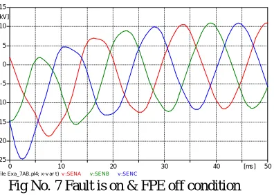
Figures 7 & 8 have display the voltage waveforms measured during line to ground fault & EFC operation condition. The waveforms correspond to the following actions of the FPE system
1.FPE open, NER closed, Closing fault 2.FPE closing, NER closed, Fault on 3.FPE Removal, NER closed, Fault on 4.Removal of FPE, NER closed, Fault off
VI. RESULT AND DISCUSSION
ISSN (Print) : 2320 – 3765 ISSN (Online): 2278 – 8875
I
nternational
J
ournal of
A
dvanced
R
esearch in
E
lectrical,
E
lectronics and
I
nstrumentation
E
ngineering
(An ISO 3297: 2007 Certified Organization)
Vol. 5, Issue 7, July 2016
Fig No. 6 No fault in system & FPE is off
These voltage wave forms have no disturbance and no more earth fault is normally off in this condition. No voltage fluctuation & all the phase operated normally.
Fig No. 7 Fault is on & FPE off condition
Ground fault is happen the voltage is suddenly start rising due to ground fault and reactance value of system.
Fig No. 8 fault open & unbalanced voltage
the capacitive voltage and become system stable.
(f ile Exa_7AB. pl4; x -v ar t) v :PHASEB v : RECA v : RECC
0 5 10 15 20 25 30 35 [ms] 40
-15 -10 -5 0 5 10 15
[kV]
(f ile Exa_7AB. pl4; x-v ar t ) v :SENA v :SENB v :SENC
0 10 20 30 40 [ms] 50
-25 -20 -15 -10 -5 0 5 10 15
[kV]
(f ile Exa_7AB. pl4; x-v ar t) v :REC A v : RECC v :PH ASEB
0 10 20 30 40 50 60 [ms] 70
ISSN (Print) : 2320 – 3765 ISSN (Online): 2278 – 8875
I
nternational
J
ournal of
A
dvanced
R
esearch in
E
lectrical,
E
lectronics and
I
nstrumentation
E
ngineering
(An ISO 3297: 2007 Certified Organization)
Vol. 5, Issue 7, July 2016
Fig No. 9 FPE closes & Fault condition clear
This is the final condition in which un balanced system get balanced condition after removing fault & voltage supply only unbalanced during of Earth fault Controller operation.
VII.CONCLUSION
As per shown result of ATP model FPE system concluded benefits are to reduced fault site voltages and, reduced over voltages & FPE switches has not exceeded the line to line voltages.
The new system has the capability to both detect high impedance faults and maintain supply during single line to ground faults. Numerous benefits of this system have been identified such as: improved sensitivity, selectivity, and fault location. There are also a number of benefits associated with the FPE method of operation but not specifically associated with this work, such as: supply continuity, fault site safety.
The result shown in the Fig 6 & 7 has fault clear through Earth fault controller without unbalanced of other phase supply. There are drawbacks associated with increasing the voltage stress at transformer neutral some time insulation of cable & NGT cubicle may be breakdown if neutral switch open during fault. For controlling arc & voltage stress at NGT switch fuse & arc controller shall be used with FPE controller.
REFERENCES
[1] IEEE Std 80-2000, Guide for Safety in AC Substation Grounding
[2] IEEE Std 81-1983, IEEE Guide for Measuring Earth Resistivity, Ground Impedance, and Earth Surface Potentials of a Ground System (Part 1) [3] IEEE Std 81.2-1992, IEEE Guide for Measurement of Impedance and Safety Characteristics of Large, Extended or Interconnected Grounding
Systems (Part 2).
[4] IS 3043 Code of Practice for Earthing September 1998
[5] N. McDonagh, ESBI, Ireland PAC World Dublin June 2010, TESTING OF ESB’s 20kV FAULTED PHASE EARTHING SYSTEM [6] N. McDonagh “Faulted Phase Earthing Using a Custom Built Controller” Dissertation as part of MSc, University of Bath, 2009
[7] H. Borland, “Influence of fault handling techniques on supply security” IEE Colloquium on Improving Supply Security on 11 kV Overhead Networks, May 1990
[8] N. McDonagh, W. Phang ESBI, Ireland PAC World Dublin June 2010, USE OF FAULTED PHASE EARTHING USING A CUSTOM BUILT EARTH FAULT CONTROLLER
[9] D. Tziouvaras, “EMTP Applications for Power System Protection”, Protection, Automation & Control World, Spring 2008.
[10] ANSI/IEEE Std 81-1983, “IEEE Guide for Measuring Earth Resistivity, Ground Impedance, and Earth Surface Potentials of a Ground System”,1983
[11] ANSI/IEEE Std 81-1983, “IEEE Guide for Measuring Earth Resistivity, Ground Impedance, and Earth Surface Potentials of a Ground System”,1983
[12] M. Mitolo, P. E. Sutherland and R. Natarajan, “Effects of High Fault Currents on Ground Grid Design”, IEEE Trans. Industry Applications, vol. 46, no. 3,May/June, 2010
(f ile Exa_7AB.pl4; x-v ar t) v :SENA v :SENB v : SENC
0 10 20 30 40 50 60 [ms] 70
-20 -15 -10 -5 0 5 10 15 20