Intelligent Load Shedding for Distributed
Generating System
M.Chindamani 1, Anitha.S 2 , Dhanalakshmi.A 3 ,Karpagam.P 4
Assistant Professor, Department of Electrical and Electronics Engineering, Sri Ramakrishna Engineering College,
Coimbatore, India1
UG Students, Department of Electrical and Electronics Engineering, Sri Ramakrishna Engineering College,
Coimbatore, India 2,3,&4.
ABSTRACT: In recent years, load shedding systems have been used in conventional under frequency relay and breaker inter lock schemes integrated with Programmable Logic Controller which typically result in excessive load shedding. An intelligent load shedding is a model driven load shedding system with predictive solution optimization techniques which improves response time and makes fasts, optimum and reliable load shedding decisions with conditions such as loss of generation, short circuits etc. This paper demonstrates the need for a modern load scheme and introduces the new technology of intelligent load shedding. Simulations of case studies for Plant energy power plant is performed to demonstrate the advantages of Intelligent load shedding methods over conventional load shedding methods from the design and operation perspectives.
KEYWORDS: ETA, intelligent load shedding (ILS), PLC, Relay, stability, TD-total demand, TG-total generation.
I. INTRODUCTION
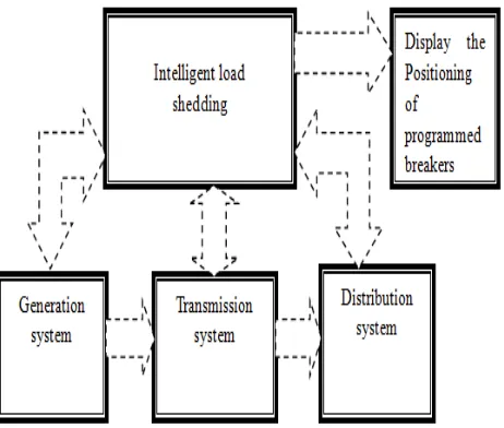
Intelligent load shedding is means to improve power system stability, by providing an adapted load control along the distribution network in situations where the power system otherwise would go unstable. The work with intelligent load shedding in this work results in various technical principles of dedicated algorithms. These algorithms intend to bring a support tool for the operating system during critical situation. The main aspects are evaluating the right amount and location of power response for a given disturbance evaluating the right time response expected in order to comply with an acceptable stability recover. In this project different case studies for plant energy plant are performed using ETAP software and this information are given to programmable logic controller (PLC).
II. CONVENTIONAL LOAD SHEDDING TECHNIQUES
A. BREAKER INTERLOCK LOAD SHEDDING
Even though its execution is fast, it has some drawbacks, listed below.
Load shedding based on worst. More loads are shed than required. Only one stage of load shedding. System modifications are costly.
B. UNDER-FREQUENCY RELAY LOAD SHEDDING
Drawbacks of this scheme are listed below. Response time is slow.
Incorrect / excessive load shedding.
ISSN (Print) : 2320 – 3765 ISSN (Online): 2278 – 8875
I
nternational
J
ournal of
A
dvanced
R
esearch in
E
lectrical,
E
lectronics and
I
nstrumentation
E
ngineering
(An ISO 3297: 2007 Certified Organization)
Vol. 5, Issue 10, October 2016
Copyright to IJAREEIE DOI:10.15662/IJAREEIE.2016.0510021 8214 C. PROGRAMMABLE LOGIC CONTROLLER - BASED LOAD SHEDDING
Main drawback of the system is the pre-defined load priority tables implementation at the PLC level that are which is done by sequential execution that curtail blocks of load and dynamic changes in the system loading, generation, or operating configuration is not taken into consideration.
III. INTELLIGENT LOAD SHEDDING SYSTEM
Intelligent load shedding calculates the minimum required MW to be shed for each subsystems according to the type and location of the disturbance, actual operating generation, spin reserve, loading configuration, load disturbance and priority. Intelligent load shedding then selects the best combination of loads (CBs) that will satisfy this requirement. All of this is executed in less than a few milliseconds after a disturbance occurs in the system for transient events or after user defined time delay for steady state overload conditions.
In Fig 1 represents functional diagrams of Intelligent load shedding. Knowledge base is most important block. It is connected to the load shedding which sends trip signals relay. The network model can be accessed by the knowledge base while monitoring the system.And the flowchart of ILS is shown in Fig.2
A.IMPLEMENTATION OF ILS
An effective load shedding approach requires a comprehensive understanding of power system dynamics and process constraints, combined with knowledge of system disturbances and Single line diagram of energy plant is shown in Fig 3. ILS helps to shed the load swiftly and hence prevents the equipments from damage and system from blackout Intelligent load shedding calculates the minimum required MW to be shed for each subsystem according to the type and location of the disturbance, actual operating generation, spin reserve, loading, configuration, load distribution, and priority. Intelligent load shedding then selects the best combination of loads (CBs) that will satisfy this requirement. All of this is executed in less than a few milliseconds after a disturbance occurs in the system for transient events or after user-defined time delay for steady-state overload conditions.
Fig 2. Flow chart of ILS
IV. IMPLEMENTATION OF ILS IN A REAL POWER PLANT
Fig 3. Single line diagram of energy plant
A. SYSTEM DESCRIPTION
ISSN (Print) : 2320 – 3765 ISSN (Online): 2278 – 8875
I
nternational
J
ournal of
A
dvanced
R
esearch in
E
lectrical,
E
lectronics and
I
nstrumentation
E
ngineering
(An ISO 3297: 2007 Certified Organization)
Vol. 5, Issue 10, October 2016
Copyright to IJAREEIE DOI:10.15662/IJAREEIE.2016.0510021 8216
houses the main 6.6kV switchgear connected to GTG. Main power feeders for other substations shall emanate from this substation.Admin MCC room: This substation in the admin MCC room feeds the electrical load of all non-plant Buildings.
V. CASE STUDY
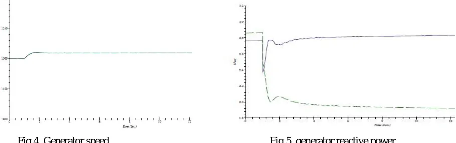
A. Study Case 1 – Tripping of large motor:6.6 kV Export pump is tripped at time T=1 seconds. a) Summary of results and Recommendations – Case 1
From the study result plots, during disturbance caused by sudden loss of MV motor load (2000 kW), it is observed that in the generation bus Bus-1, Bus-2, Bus-3 frequency disturbance is negligible and voltage is stabilized within a few cycle and it is shown in Fig 4.and Fig 5
Fig 4. Generator speed Fig 5. generator reactive power
B. Study Case 2 – Sudden loss of Generator GTG-1:Generator GTG-1 is tripped at time T=1 seconds. a) Summary of results and Recommendations – Case 2
From the study result plots, during disturbance caused by sudden loss of generator GTG-1, the generation bus, frequency disturbance is negligible and voltage is stabilized within a few cycles and it is shown in Fig 6.and Fig 7.The generation power loss is compensated by shedding loads according to the load shedding schedule for 2.8MW load. Load shedding shall be done such that during one generator failure, the power system shall continue to operate without tripping the generator due to overload.
Fig 8. Bus voltage
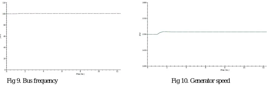
C. Study Case 3 – Tripping of Power Transformer: Power transformer is tripped at time T=01 seconds. a) Summary of results and Recommendations – Case 3
From the study result plots, during disturbance caused by sudden loss of Power transformer (MES), it is observed that in the generation bus Bus-1, Bus-2, Bus-3 frequency disturbance is negligible and voltage is stabilized within a few cycles and it is shown in Fig 9.and Fig 10. Load sharing function shall respond in reducing the two generator loads equally.
Fig 9. Bus frequency Fig 10. Generator speed
D. Study Case 4 – 3 phase fault at 6.6 kV bus (BUS-3):3 phase fault is applied at t=1.2 seconds on 6.6 kV bus (BUS-3). Fault is cleared after 400 ms (at t=1.4 seconds).
a )Summary of results and Recommendations – Case 4
ISSN (Print) : 2320 – 3765 ISSN (Online): 2278 – 8875
I
nternational
J
ournal of
A
dvanced
R
esearch in
E
lectrical,
E
lectronics and
I
nstrumentation
E
ngineering
(An ISO 3297: 2007 Certified Organization)
Vol. 5, Issue 10, October 2016
Copyright to IJAREEIE DOI:10.15662/IJAREEIE.2016.0510021 8218
Fig 11. Generator reactive angle Fig 12 Bus frequency
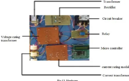
VI HARDWARE RESULT AND DISCUSSION
The simulation study was carried out in embedded controller and it is shown in Fig 13 where the transformer is given to the 3 phase supply, it energies the relay contactor and controller. It gives 9V and 15V supply to the bridge rectifier and relay driver circuit. The current transformer measures the current values using current measuring module and this current is converted into voltage using shunt resistor through voltage measuring module. The 5V controller displays the voltage and current value and this data are given to the 12V relay by converting 5V to 12V using transistor. An Alternator operates at 440V, in which inductive and resistive load of 16A and 20A are connected. These loads are operated up to 2.1A when the current rating exceeds this value, the relay send the signal to the contactor and then the particular load will be tripped from the circuit. Thus the system will be operated in stable condition.
VI CONCULSION
This paper has introduced an intelligent, optimal, and fast load shedding technology referred to as ILS. ILS combines online data, equipment ratings, user-defined control logics, and a knowledgebase obtained from power system simulation studies, to continually update Dynamic load shed tables. This system can perform optimal load shedding within 200 milliseconds from the initial occurrence of a disturbance. Thus a detailed study on Load Shedding is made. Overall Plant energy process, various cycles involved and various strategies of Plant energy were broadly discussed. A 8MW Plant energy plant has been taken for study. Overall modeling of entries plant power system is made in ETAP. The SLD of the Plant energy power plant is drawn in ETAP.ILS technology has been successfully installed and operational at several industrial facilities. Thus the Stability of the given system is maintained through intelligent load shedding.
REFERENCES .
[1] Benny McHugh, Sreto Boljevic, F Michael, Conlon, “Feasibility Studies on Technical and Economic Impact of Combined Heat and Power (CHP)” UPEC 2011 · 46th International Universities' Power Engineering Conference · 5-8th September 2011 · Soest Germany
[2] A. Niern berg, D. A. Meinnis, and K. D. Sparks, “Fast acting load shedding,” IEEE Transactions on Power Systems, Vol. 7, No. 2, pp. 873–877, 1992.
[3] E. J. Thalassinakis, E. N. Dialynas, and D. Agoris, “Method combining anns and monte carlo simulation for the selection of the load shedding protection strategies in autonomous power systems,” IEEE Transactions on Power Systems, Vol. 21, No. 4, pp. 1574–1582. 2006.
[4] Z. P. Ding, S. K. Srivastava, D. A. Cartes, and S. Suryanarayanan, “Dynamic simulation-based analysis of a new load shedding scheme for a notional destroyer-class shipboard power system,” IEEE Transactions on Industry Applications, Vol. 45, No. 3, pp. 1163–1174, 2009.
[5] R. Faranda, A. Pievatolo, and E. Tironi, “Load shedding: A new proposal,” IEEE Transactions on Power Systems, Vol. 22, No. 4, pp. 2086–2093, 2007.
[6] D. Xu and A. A. Girgis, “Optimal Load Shedding Strategy in Power Systems with Distributed Generation,” IEEE, pp. 788–793, 2001.
[7] Wiszniewski, “New criteria of voltage stability margin for the purpose of load shedding,” IEEE Transactions on Power Delivery, Vol. 22, No. 3, pp. 1367–1371, 2007.
[8]Ackermann,T.; Andersson,G.; Soder, L.; (2001). "Distributed Generation: A Definition", Electric Power Systems Research, Vol 57, 2001, pp 195– 204
[9]W. El-Khattam, M. M. A. Salama, (2004). "Distributed generation technologies, definitions and benefits", Electric Power Systems Research, Vol 71, 2004, pp 119-128
[10]Mardaneh M, Gharehpetian, G.B, (2004). “Siting and sizing of DG units using GA and OPF based technique”, TENCON 2004. 2004 IEEE Region 10 Conference
[11]A. R. Malekpour, A. R. Seifi, M. R. Hesamzadeh, (2006). “Considering Dispersed Generation in Optimal Load Shedding for Distribution Networks”, 14th Iranian Conference on Electrical Engineering, ICEE2006
[12] Load Shedding, Load Restoration and Generator Protection Using Soild-state and Electromechnical Underfrequency Relays, GET-6449,General Electric Company, Philadelphia, PA
[13] Shervin, Shokooh, Tanuj, Khandelwal, Dr. Farrokh Shokooh, Operation Technology, Inc USA 2005 [14] Jacques Tastet Dr. JJ Dai TECHNIP Operation Technology, Inc. USA 2005