Different Network Micro-Mobility Protocols and
their Performance Analysis
K Karmakar1, J S Banerjee2
1
Department of Comp Sc and Engineering, N I T, Kolkata, INDIA,
2 Department of Electronics & Communication Engineering, B I T, Kolkata, INDIA,
Abstract
-
In the recent years popularity of different wirelessdevices has increased by leaps and bounds. This is due to their portability, low cost and lesser energy consumption. But since these devices are wireless and don’t have any fixed infrastructure, they change their locations very frequently. As a result it becomes difficult to maintain an un-interrupted connectivity to these wireless devices. Situation becomes tougher when the Mobile Nodes reside in the vehicle, which is also in motion. We are now witnessing the emergence of mobile networks as a set of hosts, which move collectively as a unit, such as the ships and the aircrafts. One protocol widely used to maintain mobility is Mobile IP (MIP) or its version 6 (MIPv6). It is a better solution for host mobility but not for network mobility. A modified version based on MIP called Network Mobility Basic Support protocol (NEMO) was developed by IETF. But NEMO protocol requires a lot of global registrations and de-registrations during the handoff and could lead to heavy signalling overhead. To reduce this problem different micro mobility protocols such as Micro-NEMO and its enhanced version were developed. In this paper we have shown the motivations behind the developments of these protocols, their different versions and comparative analysis of their respective performances in terms of Data transfer time, Signalling time, Response time and Delay in mobile nodes.
Keywords — MIPv6, CIP, HAWAII, NEMO, Micro-NEMO,
Data transfer time, signalling Time, Response time, Delay time.
I.NTRODUCTION
Popularity of different wireless devices has increased in the last few years. This is because these devices are portable, cheaper and also consumes lesser energy. They change their locations frequently. As a result, it becomes very difficult to maintain constant connectivity with these fast moving devices. When a single Mobile Node (MN) moves from its existing location to a new location, this kind of mobility is called Host mobility. But, if a set of hosts move collectively as a unit inside a vehicle like ships and aircrafts the mobile nodes that are present inside the vehicle also move. Networks in
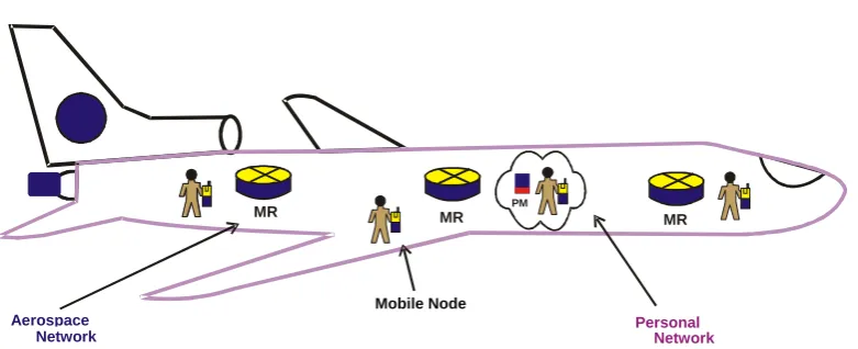
transportation vehicle such as buses, trains, ships, aircraft etc. are treated as mobile networks and this kind of mobility is known as Network Mobility. It is comparatively easy to provide uninterrupted Internet connectivity to the individual devices but difficult in case of network mobility. People of the modern cities spend a lot of time on the vehicles. Different public transportation systems like local or metro trains, buses and even the private vehicles carry a lot of passengers everyday and among them a large numbers of Internet users are present who want a constant un-interrupted Internet connectivity while moving around in the vehicles. A typical network mobility scenario is illustrated in Fig.1.
Fig.1 shows a typical practical example of network mobility. In this example we see an aircraft carrying some passengers. Some of the passengers are carrying mobile phones, laptops, Personal digital assistant (PDA) with them while some of them are carrying the entire Personal area network (PAN), which is composed of different mobile devices. Each and every devices and mobile nodes are expected to get uninterrupted connectivity.
Fig. 1: Network Mobility
a survey and made performance analysis of different existing micro and network mobility protocols. This paper is organized as follows. Section I has been used as introduction, in section II we discussed previous works that has been carried out so far on network mobility. In section III, a brief introduction on NEMO and other similar basic support protocols has been described using proper diagram. In section IV the concept of micro mobility has been introduced. Different existing micro-mobility protocols are discussed in Section V. In section VI and VII an analysis of their performances has been shown. Section VIII concludes the paper.
II. PREVIOUS WORKS
Providing uninterrupted Internet connectivity is a challenging area of research and was discussed in section I. Mobile IP (MIP) protocol can be used to provide uninterrupted connectivity for individual mobile devices. According to MIP, when a mobile node enters into a new foreign network, it obtains a new Care of Address (COA). Then it informs its Home Agent (HA) and makes a registration with the HA as well as with the Correspondent Node (CN). But in this process, a lot of global registrations and de-registrations are required which ultimately leads to a lot of overheads. This is the major weakness of MIP. So, new protocols were developed based on MIP and different micro/macro mobility protocols1 such as Cellular IP [4, 6, 14], HAWAII [5, 9, 10, 11], Hierarchical Mobile IP [7, 8] etc have been developed. These protocols are good in handling micro-mobility related problems in individual hosts. In Cellular IP, network is
1
Macro-mobility protocol deals with mobility across several networks while Micro-mobility protocol deals with the mobility within the single network or subnet
connected to the Internet backbone by a router known as gateway. Duty of this gateway is to provide the local IP address i.e. the COA to the individual hosts. According to HAWAII, domain root router works as the gateway, which connects the domain to a backbone and acts as a foreign agent (FA) to all the mobile nodes of that domain. In Hierarchical Mobile IP (HMIP), a new element is introduced called Mobility Anchor Point (MAP) which maintains the local mobility.
The above mentioned discussions on micro mobility protocols are confined mainly to host mobility. But, they are not very good solution to the mobility of networks. In search of a better solution to the mobility of network problem, Internet Engineering Task Force (IETF) has developed the network mobility basic support protocol or NEMO [20, 21, 22]. NEMO has been derived from MIPv6 and is an extension of it. According to NEMO mobile networks can be accessed via specific gateways only called Mobile Routers (MR). NEMO uses MR for managing local mobility. A mobile network must have at least one MR serving them. The MR also works as the default gateway for the Mobile Network.
The concept of using MR for handling of mobility of a set of mobile devices is revolutionary and has come to knowledge since the year 1990. In their paper, “MINT- a Mobile Internet Router”, Hager et al [23] described the concept of the use of a router because it had enough power to perform all the required communication protocol operations and to enable connectivity for nodes. Use of MR for network mobility was also specified in some research papers and publications [1]. Some research works on network mobility are eMotion, InternetCAR, Fleet Net Internet on the Road etc.
PM
Aerospace Network
Mobile Node
Personal Network MR
MR
III. DIFFERENT NETWORK MOBILITY PROTOCOLS
III.I NEMO protocol: NEMO basic support protocol [19, 20] is an extension of MIPv6 [1, 2, 3]. It enables the mobile networks to attach to different points in the Internet. It also allows every node in the mobile network to be reachable while moving around in the same network or some different networks. The protocol is designed in such a way that the network mobility becomes transparent to the nodes inside the mobile network. A mobile network is a network segment or subnet that can move and attach to arbitrary points in the routing infrastructure. A mobile network may consists of multiple and nested subnets. According to NEMO, an MN can only accessed only via specific gateways called MR that manages its movement. There must be at least one MR, which manages the mobility of the MN present in the mobile network. The MR can act either as a Mobile Host (MH) or as a MR depending on the situation and requirement. The MR, which connects the network to the Internet, runs the NEMO Basic Support protocol with its Home Agent (HA). The Home address is configured from a prefix aggregated and advertised on the home link or from the prefix delegated to the MR. The MR can have more than one Home addresses if there are multiple prefixes in the home link. At the time when the MR moves away from the Home link and visits a new area, it acquires a Care-of Address (COA) from the visited link. As soon as the mobile router acquires a Care-of-Address (COA), it immediately sends a binding update to its Home Agent (HA). When the HA receives this binding update, it creates a cache entry binding the MR’s Home Address to its COA at
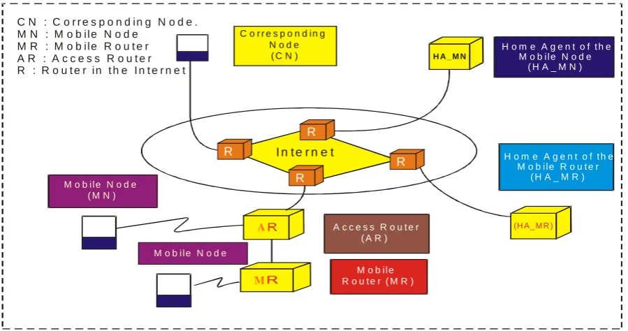
the current point of attachment. If the MR wants to work like a MR, it indicates this by setting the Mobile Router Flag (R) in the packet for the Binding Update (BU). It may also include other information like information about the Mobile Network Prefix in the BU. In this way the HA can come to know the data packets and can forward them to the MR that was originally sent to the MN. In some cases, different types of mechanisms called static configuration is used for identifying the MR. In this cases, instead of using any prefix information in the binding updates, the HA forwards all prefixes owned by the MR when it receives a binding update request from the MR with the MR flag set. The HA acknowledges the binding update by sending a binding acknowledgement to the MR. Once the binding process is finished, a bi-directional tunnel is established between the HA and the MR. The end points of the tunnel are the MR’s COA and address of the HA. When a CN sends a data packet to a node in the mobile network, the packet is routed to the HA that currently has the binding for the MR. When the HA receives a data packet meant for a node in the mobile network, it tunnels the packet to the current COA of the MR, which, in its turn decapsulates the packet and forwards it onto the interface where the mobile network is connected. The Mobile Router and the Home agent can run a routing protocol through the bi-directional tunnel. Unfortunately NEMO basic support protocol does not attempt route optimization. In NEMO data packets have to travel through multiple agents before reaching to their intended destination. In fig. 2, we have shown the simple scenario of NEMO basic support protocol.
C N : C o r r e s p o n d i n g N o d e . M N : M o b ile N o d e
M R : M o b ile R o u t e r A R : A c c e s s R o u t e r R : R o u t e r i n t h e I n t e r n e t
C o r r e s p o n d i n g N o d e
( C N ) H A _ M N H o m e A g e n t o f t h eM o b i l e N o d e ( H A _ M N )
R
R
R H o m e A g e n t o f t h eM o b i l e R o u t e r
( H A _ M R )
( H A _ M R ) M o b i l e N o d e
( M N )
A A c c e s s R o u t e r ( A R )
M
M o b i l e R o u t e r ( M R )
M o b i le N o d e
R I n t e r n e t
III.II Bus NEMO protocol:
Another significant development based on NEMO protocol is Bus NEMO protocol [22]. This protocol handles mobility for vehicular adhoc network (VANET)2. This protocol was designed for the running vehicles in the high ways. According to this protocol, each vehicle in the VANET has one Mobile Router (MR) having two interfaces, one is Wi-Fi3 and another one is Wi-MAX4. In Wi-MAX or Wi-Fi environment, the Base station (BS) is managed by the Access Router (AR). The Home Agent (HA) records the vehicle’s new location and the Correspondent Node (CN) serves as a remote server. Moving vehicles like cars or buses connect to the Internet through the MR using the wireless communication technology e.g. IEEE 802.11 or 802.16. When a Mobile Node (MN) moves to a new subnet, the MR receives broadcast packet from the target BS and performs the handoff procedure. This handoff procedure contains signal measurement procedure, network layer movement detection procedure, duplicate address detection procedure and registrations. This protocol is based on the concept of IP passing [28]. At the time when a vehicle leaves the area of the current base station (BS) and moves to the region of new base station, it gets its new IP address from the inbound vehicle by IP exchange or from the outbound vehicle by IP passing. There are two network-based architectures for this protocol - one is called a) Real Bus Network Mobility Protocol and the other one is called b) Virtual Bus Network Mobility Protocol.
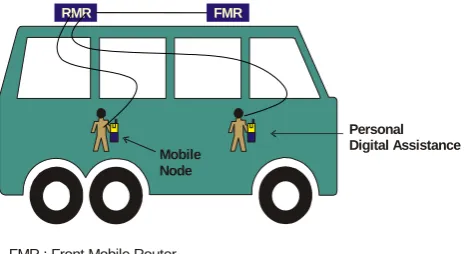
III.II.I Real Bus Network Mobility Protocol:
Network mobility scenario for Real Bus Network Mobility protocol [22] is shown in Fig. 3. It is based on the real bus architecture. In this case the vehicle have two Mobile Routers (MR) connected by wire. One MR is called Front mobile router (FMR) and the other is called Rear mobile router (RMR). Both the mobile routers are connected by wires directly. The FMR performs the pre-handoff procedure while the RMR serves as MNs and maintains connectivity with the Internet. The MNs connect to the Internet via the RMR. When
2
Vehicular Ad-Hoc Networks (VANETs) are special kind of Mobile Ad-Hoc Networks (MANETs), where wireless-equipped (road) vehicles form a network without any additional infrastructure [30].
3
Wi-Fi is a popular wireless networking technology that uses radio waves to provide wireless high-speed Internet and network connections. It is a wireless local area network technology designed to add mobility to wired LAN. It is based on the IEEE 802.11 standards.
4
WiMAX is an IP based, wireless broadband access technology, which is based on IEEE 802.16 standards and provides performance similar to Wi-Fi networks. Wi MAX was designed primarily for a metro area broadband wireless access service.
there is no neibouring vehicle on the lanes of the opposite direction, the MR acquires the IP address from the vehicle on the lanes of the same direction. When a MN moves to a new subnet, the MR receives the broadcast packet from the target base station and performs the required handoff process. The bus is equipped with the Wi-Fi and WiMAX interfaces, where the Wi-Fi interface is for Vehicle to Vehicle communication and the WiMAX interface is used to connect to the Internet. When there is a movement of the vehicles, MRs of the vehicles acquires IP addresses. When two buses on the opposite directions will enter into a new subnet, mobile routers exchanges their IP addresses. On the other hand, when the MR of a vehicle is going to leave the target base station’s communication region, it passes its IP address to the mobile router of its back vehicle. So, working principle of this protocol is divided into several phases like IP acquiring phase, cooperation between the MRs phase, route redirection phase etc.
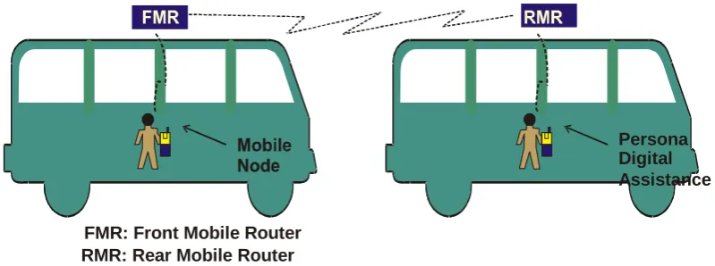
III.II.II Virtual Bus Network Mobility Protocol:
Another variation of Bus NEMO protocol is Virtual Bus Network Mobility protocol [22]. Unlike Real Bus NEMO, here MRs are not connected by wires. In this case, each vehicle has a single MR having Wi Fi and Wi MAX interfaces. Two or more vehicles moving on the lane of the same direction may form a group as a virtual bus and may cooperate with each other. When there is a movement of the vehicles, MRs of the vehicles acquire IP addresses. Virtual Bus NEMO protocol works on the principle that when two buses on the opposite direction enter into a new subnet, MR exchanges their IP addresses. When the MR of a vehicle is going to leave the communication region of the target base station, it passes its IP address to the mobile router of its back vehicle. If no vehicle is present on the lane of the opposite side, then the moving vehicle gets its IP address from the Dynamic Host Configuration Protocol (DHCP) server. A scenario of this protocol is shown in Fig.4, which is very similar to that of the real bus scheme.
Personal Digital Assistance
RMR FMR
Mobile Node
FMR : Front Mobile Router RMR : Rear Mobile Router
Persona lDigital Assistance
FMR: Front Mobile Router RMR: Rear MobileRouter
Fig. 4: Virtual Bus NEMO protocol
IV. MICRO-MOBILITY
Mobility management schemes can be applied to different categories of mobility scenarios like macro-mobility and micro-mobility. Macro-mobility deals with mobility across several networks and micro-mobility deals with mobility within a single network. Since macro-mobility deals with large-scale area network, it requires a robust protocol to handle such situation. Naturally macro-mobility protocols require a lot of global registrations and de-registrations leading to high signalling overheads, which ultimately leads to degradation of the performances. In comparison, micro-mobility deals with the micro-mobility within a comparatively small area and handles local movements of locally administered domain. Thus macro-mobility protocol is not suitable for handling micro-mobility.
NEMO is a macro-mobility protocol and uses the concepts of MR for handling mobility collectively. Every time whenever the MN moves from its present location to a new location a new registration is needed to be done with the HA
.
Registration latency as well as move detection latency increase as the MN moves to a new location. This mechanism produces a lot of traffic, creating congestion problems. To handle the local movement of different mobile devices in a more efficient way micro mobility protocols have been developed. A micro-mobility protocol behaves as: When the MN comes to a new domain, only one registration need be done. Local movement of the MN from one location to another must be governed by the protocol. This is transparen
t
to the HA and the rest of the Internet. In fact, for the HA, each wireless domain will become a Mobile IP subnet. Latency and control traffic across the whole network are thus extremely reduced. More efficient protocols are required for handling local mobility. Based on this requirement further research works was carried out and different micro-mobility protocols have been derived which are discussed in the subsequent sections.
V. DIFFERENT MICRO-MOBILITY PROTOCOLS
V.I Micro-NEMO:
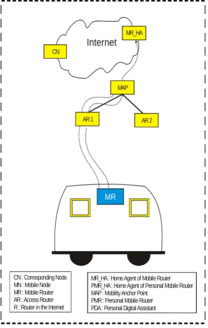
One of the major developments that support the concept of micro-mobility along with the NEMO protocol is known as Micro-NEMO [26]. Micro NEMO was derived from NEMO and is used to support simultaneous local movements within a certain region. It is a blend of micro-mobility and basic NEMO protocol. The characteristics of both the NEMO and micro-mobility are preserved in the Micro-NEMO. According to this protocol, a Mobility Anchor Point (MAP) is used to maintain the local mobility. Every vehicle has an MR inside it. As soon as a vehicle enters into the micro-domain, MR of that vehicle starts operating and obtains two new addresses: One is called on-link care-of-address (LCOA) and the other is regional care-of-addresses (RCOA). Then the MR registers with the MAP which takes care of all the local registration latency and forwards the data packets through the HA of the MR, MAP and reaches the MN finally. It achieves low handoff latency and has minimal signalling cost. Additionally, it is transparent to all the mobile hosts within the same network. But micro-NEMO has a major drawback. Data packets may have to travel a lot of paths before arriving at the actual destination. This problem is called pinball routing problem. Fig.5 illustrates the working procedure of Micro-NEMO protocol.
V.II Enhanced Micro-NEMO:
will be much tougher if the number of intermediate agents increases. This pinball routing problem can be solved in enhanced micro-NEMO [26]. In the case of the enhanced micro-NEMO every MN is to register only once. After that CN forwards the data directly to the MN of the vehicle inside the micro domain. If we consider of any personal area network coming in a vehicle then data flow will be as follows: MR will inform the HA of MR about the location information of the nodes inside the moving network followed by performance of home registration with the HA. After the registration is complete, CN will send the data directly to the MN through MAP. One of the significant improvements of Enhanced Micro-NEMO over Micro-NEMO is that multiple tunnelling is absent in Enhanced Micro-NEMO. As a result, end-to-end delay between CN and MN is reduced. The overhead in packet tunnelling is also lower than that of Micro-NEMO. Fig. 6 shows the working principle of Enhances Micro-NEMO protocol.
PMR_HA MR_HA
Internet
MAP CN
MR
PMR
CN : Corresponding Node. MN : Mobile Node MR : Mobile Router AR : Access Router R : Router in the Internet
MR_HA : Home Agent of Mobile Router PMR_HA : Home Agent of Personal Mobile Router MAP : Mobility Anchor Point
PMR : Personal Mobile Router PDA : Personal Digital Assistant
AR 1 AR 2
MR_HA
Internet
MAP CN
MR
CN : Corresponding Node. MN : Mobile Node MR : Mobile Router AR : Access Router R : Router in the Internet
MR_HA : Home Agent of Mobile Router PMR_HA : Home Agent of Personal Mobile Router MAP : Mobility Anchor Point
PMR : Personal Mobile Router PDA : Personal Digital Assistant
AR 1 AR 2
Fig. 5: Signal flow of micro-NEMO protocol
Fig 6: signal flow of Enhanced micro-NEMO protocol
VI. PERFORMANCE ANALYSIS
In this paper we focussed on network and micro mobility. Since one of the popular protocols in handling micromobility is MIP we started our discussion with it. To remove the limitations of MIP in handling micromobility different protocols were developed like NEMO, bus NEMO etc. In this section we will show a comparative study of the performances of these protocols depending on different parameters which are discussed in the following sections:
VI.I PARAMETERS:
T: Data Transfer time S: Signalling time R: Response time D: Delay in the node
Data Transfer time (T) is the time taken by a data packet to reach the MN from CN. It is the sum total of the delay times taken at the intermediate entities.
Response time (R) is the sum of the data transfer time and the signalling time.
Delay in the node (D) is the sum of the processing delay and the link delay.
In this analysis, we have used the network architecture of different protocols discussed above. All the calculations are based on the architectural model that a packet reaches its destination from the source point via some intermediate agents.
VI.II ARCHITECTURE:
VI.II.I NEMO:
The working principle of NEMO basic support protocol is explained in the simplified architecture as shown in Fig. 7. Data packets sent by the CN will reach the MN via some intermediate agents as shown in the fixed line. Data transfer time is the total delay time as shown in the equation (1). In NEMO, only one binding update message is done with the HA. According to NEMO, every message that makes a binding update with the HA must be acknowledged properly. So, the signalling time can be calculated as equation (2). No additional signalling is required before the actual delivery. Therefore, Response time and Data delivery time is the same and is calculated as equation (3).
NEMO has been derived from IPv6. And other three protocols have been derived based on the working principle of NEMO. Since these protocols are similar in nature they can be analysed using the same parameters. Data sent from the CN reaches the MN via the HA. We have performed our analysis with respect to four parameters namely data transfer time, signalling time, response time and delay in the node. Delay can be of two types- link delay and processing delay. But, processing delay at every node is very small and negligible compared to that of the link delay. So, in our analysis we have taken that delay in the node is equal to the summation of the link delay only. In the following section, we have described different types of parameters used in our analysis.
Fig. 7: NEMO basic protocol architecture
) 3 ...( ... ... ... ... ... ... ... ... ... ... ... ... ... T
R
) 2 ...( ... ... ... ... ... ... ... ... ... D
* 2 D
* 2 S
) 1 ....( ... ... ... ... ... ... D
D D
D T
NEMO NEMO
HA AR AR
MR NEMO
MN MR MR
AR AR
HA HA
CN NEMO
VI.II.II Bus NEMO protocol:
Bus NEMO protocol is a little bit different from other protocols discussed above. In the above section, two different versions of bus NEMO protocols have been described. However, here we have tried to draw a general simplified architecture of this protocol (Fig. 8) combining both the two versions discussed above. Two different ARs-
pAR and nAR are used in the actual protocol but in this diagram, we have combined them. Corresponding times for data transfer and signalling are calculated and shown in equation 4 and 5 respectively. After initial registrations and binding updates are completed, no further binding is required. So, response time of a message is equal to the data transfer time, which is shown in equation 6.
) 6 ...( ... ... ... ... ... ... ... ... ... ... ... ... ... T R ) 5 ...( ... ... ... ... ... ... ... D * 2 D * 2 D * 2 S ) 4 ( ... ... ... ... D D D D D T NEMO _ BUS NEMO _ BUS HA AR AR FMR FMR RMR NEMO _ BUS MN RMR RMR FMR FMR AR AR HA HA CN NEMO _ BUS VI.II.III Micro-NEMO:
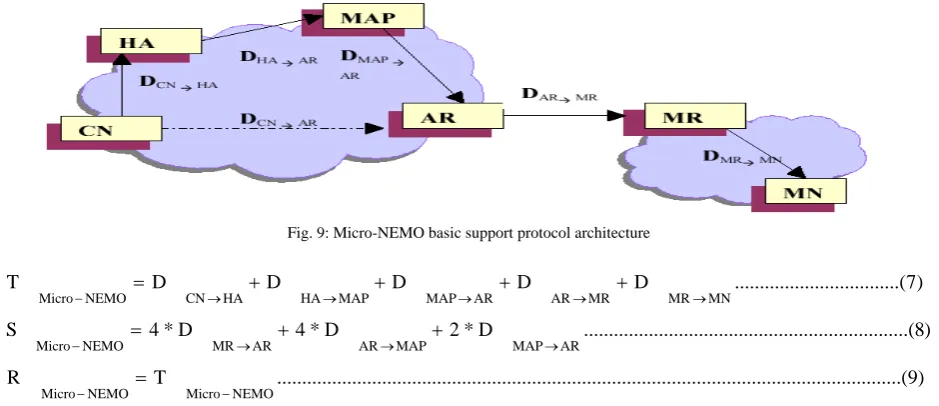
Micro-NEMOwas derived from NEMO and as such includes the basic concepts of NEMO and micro-mobility. In Micro-NEMO an additional component is required with the existing components of NEMO to maintain the mobility locally. In Fig.9, we have drawn the simplified architecture of Micro-NEMO. The additional component required over NEMO is nothing but a mobility anchor point (MAP). Another major difference is that unlike NEMO, in
Micro-NEMO two different binding updates are required. One is the path MR-MAP and another is through the path MR-HA. So, the corresponding equations of data transfer time, signalling time and response time are shown in following derivations. In Micro-NEMO, like NEMO, no additional signalling is required while sending any data packet to the destination. So, here also response time will be equal to that of data transfer time.
Fig. 9: Micro-NEMO basic support protocol architecture
) 9 ...( ... ... ... ... ... ... ... ... ... ... ... ... T R ) 8 ...( ... ... ... ... ... ... D * 2 D * 4 D * 4 S ) 7 ...( ... ... ... D D D D D T NEMO Micro NEMO Micro AR MAP MAP AR AR MR NEMO Micro MN MR MR AR AR MAP MAP HA HA CN NEMO Micro
VI.II.IV Enhanced Micro-NEMO:
Enhanced Micro-NEMO is an extension of Micro-NEMO where the pinball routing problem of Micro-NEMO was solved. In Fig.10 we have drawn the simplified network architecture of Enhanced Micro-NEMO. In this architecture, an additional component -- a MR of the PAN called Personal Mobile Router (PMR) -- is incorporated. Data transfer time is
faster than Micro-NEMO since here route optimization is done. Response time is same as NEMO and Micro-NEMO. In Micro-NEMO, like NEMO no additional signalling is required while sending any data packet to the destination. So, here also response time will be equal to that of NEMO. Corresponding data flow and signal flow is shown in equations 10, 11 and 12.
) 12 ...( ... ... ... ... ... ... ... ... ... T
R
) 11 ( D
* 4 D
* 4 D
* 2 D
* 2 D
* 2 S
) 10 ...( ... ... ... D
D D
D T
NEMO cro EnhancedMi NEMO
EnhanMicro
AR MAP MAP
AR AR
MR AR
PMR MR
PMR NEMO
EnhanMicro
MN PMR PMR
AR AR
MAP MAP
CN NEMO
EnhanMicro
VII. EVALUATION
In section VI.II, we have shown the simplified network architecture of different Network Mobility and micro-mobility protocols and derived the corresponding equations depending on different criteria like data transfer time, signalling time and response time. In the following section, we are showing a comparison of their performances in terms of these criteria.
VII.I Data transfer time:
Let us refer to the diagrams starting from Fig.7 to Fig.10. If we look at them carefully, we will notice that the
data transfer time is different for NEMO, bus NEMO and Micro-NEMO protocols since in these cases data packets pass through different numbers of intermediate nodes. Now, let us make an analysis of data transfer time of different protocols. Data packets that reach from CN to AR may be constant in optimal routing and we assume it as P. Data transfer delay in case of triangular routing is as follows: a) through HA only is same for all cases and b) through HA and MAP is same for all cases. Data transfer time from AR to MN through one MR is M1 and through more than one MR is Mn.
D CN->HA => P ………...(13)
D AR->MR + D MR-> MN => M1………(14)
D AR->MR + n * D MR1-> MRn ………..(15)
Let us now put the above results graphically in Fig. 11. In the graph Along X-axis we plotted the Data transfer time (T) and along Y-axis we plotted Routing Path distance. T will increase with the increase of the intermediate agents from CN to AR. This is because an increase in the number of intermediate agents means an increase in the delay time. Among all the protocols discussed so far, NEMO will take lesser time to transfer a packet from CN to MN. Bus NEMO will take more time than NEMO because here the number of MR increases in its way from AR to MN (But, it may be reduced drastically if route optimization method is followed. In that case RMR of the bus NEMO will get data directly from the CN). T will be lower in Enhanced Micro-NEMO than that of Micro-NEMO because in the enhanced version route optimization is followed. Since route optimization is followed, value of T will be lower in Enhanced Micro-NEMO to that of Micro-NEMO. Difference between M2 and M3 indicates that difference.………..
diff….……….. ………
…
.
Fig. 11: Data transfer graph
.
Bus NEMO
NEMO
Data Transfer time (T) P
M1 M2
M3
Enhanced micro-NEMO Micro-NEMO
VII.II Signalling time:
Signalling time of different protocols has been shown in the previous section. Signalling time will increase with the increasing numbers of binding updates. Number of the binding updates may increase if the number of agents increases in the protocol architecture. Number of required binding updates is maximum in the Enhanced Micro-NEMO, followed by Micro-NEMO, Bus NEMO and NEMO respectively. It is minimum in NEMO as all the mobile hosts within the same mobile network will update their location information through single binding updates. In the Fig. 12 we have shown graphically the relation between the signalling times of different protocols.………
sssssssssssssssssssssssssssssssssssssssssssssssssssssssssssssss
Fig 12: Signalling time graph
VII.III Response time:
Response time is the sum of the link delay time and the signalling time. In the above section we have discussed four protocols. While reaching the MN for delivery of data from the CN, no additional signalling time other than the normal time taken by a packet to reach the destination following its normal path, is required in any of the four protocols discussed above. Among these four protocols, the concept of micro-mobility is introduced in Micro-NEMO and its Enhanced version only. Moreover, the route optimization technique is followed in Enhanced Micro-NEMO. So, we can conclude that minimal response time is required in Enhanced Micro-NEMO, since it follows route optimization technique.
VIII. CONCLUSION
Designing a network micro mobility protocol is always difficult. Very few research works have been done so far on this field. In this paper we discussed different existing network mobility and micro mobility protocols and made a brief comparison of their performances based on different performance measurement criteria. Further improvement can be done on the existing work which is an active area for research for future research scholars.
REFERENCES
[1] C. Perkins “IP Mobility Support for Ipv4”. RFC 3344, IETF Network Working Group, August 2002 Oct.
http://www.ietf.org/rfc/rfc3344.txt.
[2] C. Perkins, “IP Mobility Support”. Internet RFC 2002, October 1996.
[3] Deering, S. and R. Hinden, "Internet Protocol, Version 6 (IPv6) Specification", RFC 2460, December 1998.
[4] A. Campbell, J. Gomez, C. Wan, S. Kim, Z. Tur’anyi, A. Valk’o, “Cellular IP”, Internet Draft-ietf- mobileip-cellular-00-txt, December 1999.
[5] Ramjee, R.; Varadhan, K.; Salgarelli, L.; Thuel, S.R.; Shie-Yuan Wang; La Porta, T, “HAWAII: A domain-based approach for supporting mobility mobility in wide-area wireless networks”, IEEE/ACM Transactions on Network, Volume: 10, issue 3, June 2002 pp.396-410.
[6] A. T. Campbell et a., “Design, Implementation, and Evaluation of Cellular IP”, IEEE Pers Communication, vol 7, no 4, August 2000, pp. 42-49.
[7] C Castelluccia, L Bellier, Hierarchical Mobile Ipv6, Internet Draft, draft-castelluccia- mobileip-hmipv6-00.txt, Work in Progress, July 2000.
[8] H. Sollman et al., “Hierarchical MIPv6 Mobility Management,” IETF draft, draft-ietf-mobileip- hmipv6-05.txt, July 2001, work in progress.
[9] M. Mansoor, A. Ghneimat, J. E. Mellor, “Performance Evaluation for Mobility Management Protocols in Cellular IP and Hawaii Mobile Networks” UbiCC Journal - Volume 3 Number 1, Volume 3 No. 1, 2/15/2008.
[10] R Ramjee, “IP Micro-Mobility Support Using HAWAII”, draft-ietf-mobilein-hawaii-txt work in progress.
[11] A. T. Cambell & J. Casterllanos, “IP Micro-Mobility Protocols” ACM SIGMOBILE Mobile Computing and Communications Review Volume 4, Issue 4 Year of Publication: 2000.
[12] A T. Campbell, J. Gomez, S. Kim, C. Wan etc. “Comparison of IP Micro Mobility Protocol”, IEEE Wireless Communications Magazine Volume: 9 Issue: 1 Year: 2002.
[13] F Nazir, R Boreli, S Herborn, “A Case Study for Mobility Management Protocol Co-existence”, IEEE Conferences on Cross Layer Design, 2009 IWCLD '09. Second International Workshop on 20-21 Sept. 2007.
[14] I F. Akyildiz, J Xie, And S Mohanty, “A survey of Mobility Management in Next-generation All-IP-based wireless systems” IEEE Wireless Communications, special issue on Mobility and Resource Management, vol. 11, no. 4, pp. 16-28, August 2004. [15] D. Johnson, C. Perkins, and J. Arkko, “Mobility Support in IPv6”,
IETF RFC 3775, June 2004.
[16]A. Misra et al., “Autoconfiguration, Registration, and Mobility Management for Pervasive Computing,” IEEE Pers. Commun., vol. 8, Aug. 2001, pp. 24–31.
[17]J. Kempf, "Problem Statement for Network-Based Localized Mobility Management (NETLMM)," RFC 4830, Apr. 2007. [18] Thubert, P. Wakikawa, R., and V. Devarapalli, “Network Mobility
(NEMO) Home Network Models", RFC 4887, July 2007. [19] V. Devarapalli, R. Wakikawa, A. Petescu, P. Thubert, “Network
Mobility (NEMO) Basic Support Protocol”, Network Working Group, RFC 3963 Jan. 2005.
[20]I. Soto, C. J. Bernardos, M. Calderson, and A Banchs, “NEMO-Enabled Localized Mobility Support for Internet Access in Automotive Scenarios”, IEEE Communications Magazine Volume: 47, Volume: 47 Issue: 5 Date: May 2009.
[21]Y. Chen and C. Cheng, C. Hsu, G. Chiu, “Network Mobility Protocol for Vehicular Ad Hoc Networks” IEEE Wireless Communications and Networking Conference, 2009, WCNC 2009. 5-8 April 2009.
Micro-NEMO
Bus NEMO
NEMO
Number of Binding Updates
Signalling time
[22] Hager R., Klemets A., Maguire G. Q., Reichert F., Smith M. T. “Mint- A Mobile Internet Router”, 1st International Symposium on Global Data Networking, Cairo Egypt. Dec. 13-15, 1993. [23] B McCarthy, Dr. C. Edwards, Dr. M. Dunmore, “Using NEMO to
Extend the Functionality of MANETs” Communications Workshops, 2008. ICC Workshops '08. IEEE International Conference on. pp. 455-460.
[24] E Perera, V Sivaraman, A Seneviratne, “Survey on Network Mobility Support”, ACM SIGMOBILE Mobile Computing and Communications Review, Volume 8 , Issue 2 Year of publication: April 2004.
[25]J. Hu, C. Chou, M. Sha etc., “On the Design of Micro-Mobility for Mobile Network”, IFIP International Federation for Information Processing 2007 EUC Workshops 2007, LNCS 4809, pp. 401–412, 2007.
[26] T. Ernst, “Network Mobility Support Goals and Requirements”, IETF RFC 4886, July 2007.
[27] T. Arnold, W. Lloyd, and J. Zhao, “IP Address Passing for VANETs,” vol. IEEE International Conference on Pervasive Computing and Communications (PERCOM), Hong Kong, pp. 70-79, March 2008.
[28] S. Schnaufer, H. F¨ußler, M. Transier, W. Effelsberg “Vehicular Ad-Hoc Networks: Single-Hop Broadcast is not enough”, Proceedings of 3rd International Workshop on Intelligent Transportatio (WIT), pp. 49-54, March 2006, Hamburg, Germany. [29] K. K & J S Banerjee, “A Hierarchy of Micro and Network
Mobility Protocols”, Poceedings of IEMCON 2011 organised by IEM in collaboration with IEEE on 5th & 6th of Jan, 2011 at Kolkata, INDIA.