Am Implementation Of Orwell Model Simplifications For
Network Level Simulation
1Sandip Banerjee1, Dr. R.P.Singh2
1,2Department of Computer Science & Engineering, Sri Satya Sai University of Technology and
Medical Sciences, Sehore, MP
Abstract
Rings form one of the three basic types of L.A.N. topology (the others being star and bus) and three basic types of protocol have been developed for use with them. By far the most popular of these are token based protocols, whereby the node holding a token is given exclusive access to the ring. Register insertion is another alternative; messages can be inserted onto the ring, delaying any existing traffic by passing it through a shift register. The third, but nowadays less favoured, approach is to use a slotted ring protocol: the ring is divided into slots which circulate around the ring; a node wishing to transmit a message waits until an unfilled slot is found, changes the header and transmits the message in the body of the slot.
Slotted ring protocols were unpopular for several reasons: a monitor node is required to ensure that slots that become corrupted can be identified and regenerated (correct behaviour of the ring is critically dependent on correct behaviour of the monitor); to get a reasonable number of slots onto the ring delays have to be inserted at each node and one node, normally the monitor, has to be able to adjust its delay so that there are an integral number of slots; and the -efficiency of slotted rings is generally poor since the ratio of header to body is normally high. Its greatest advantage over token-based protocols, however, is that more that one node can be transmitting information at a time, using different slots on the ring. Acknowledgement of delivery is normally made by releasing the slot at the source (correct receipt there is taken to imply correct delivery at the destination); the node may not refill a slot that it has just released, ensuring that the slot is passed to the next node and thereby ensures fair access to all nodes on the ring. A typical implementation of a slotted ring is the Cambridge Ring protocol (British Standard BS6531).
Examination of existing protocols has indicated that those based on a slotted ring are probably the best suited for carrying delay-sensitive speech, but simulation studies of high-bandwidth Cambridge Rings have indicated that there are still significant limitations when operated under high load and, further, load control is difficult since there is no relevant parameter that can easily be extracted from the ring. The Orwell protocol was developed after making a detailed study of the limitations of the Cambridge Ring protocol: it was found that by introducing destination release of slots, and by adding a novel, distributed, load control mechanism to bound access delays, a viable level of performance could be obtained. For higher capacity networks multiple, synchronized, rings can be used and such a network is known as an Orwell Torus.
1. Introduction
Whilst detailed simulations of a single ring have been made, under a variety of load
and traffic services, there has, as yet, been very little investigation made into the
behaviour of an Orwell torus, or ring behaviour in multi-ring systems. The reason
for this, at least in part, is because of the large amount of simulation time required to
investigate networks of Orwell rings: a single simulation run of one ring takes,
typically, a couple of hours on a VAX, or three times as long on a Sun 3/50
work-station for just a couple of seconds of simulated time.
There are three main options available to try and reduce the amount of time required
for simulation. The first and, almost certainly, least feasible option is to use a
larger and faster conventional computer than a VAX; this may reduce the amount
of C.P.U. time required, but it is unlikely to decrease the total time for one
simulation because of the higher demand placed on such machines. The second option
is to break down the simulation model into processes that occur concurrently and to
redesign the model to take advantage of parallel processing architectures such as the
computer; this option looks promising, despite the fact that an individual processing
element will have less power than some single C.P.U. machines, because the total
power can be increased by simply using more processors. The third option is to
create a new model that has the same external functionality as (or as close as
possible to) the original model, but to make simplifications internally in order to
reduce the computational requirements: if successful this third option can either be
used on its own, with the original computer, or with either of the other options to
reduce simulation time still further. This chapter considers various simplifications of
the model of the Orwell protocol that were investigated while attempting to reduce
the amount of computation required during simulation. All the results included here
are based on simulations using the Orwell simulator [7, 8], written in Simula '67, and
on modifications made to that program.
The full specification of the Orwell protocol, detailing its running actions, start-up
procedures and details for ensuring slot integrity is available in the specification
document [1], but an overview of the running actions is given below for completeness.
2.1 Ring Actions
An Orwell ring consists of a series of nodes connected by a closed communications
loop, figure 1. A number of slots circulate around the loop in a single direction. Each
of the slots may be in one of three states: full, empty (known as trial) or reset; these
states are explained below.
Each node maintains a counter, known as a d-counter, whose initial value is an
indication of the traffic that the node has agreed to carry. Each time a cell arrives at a
node it is placed in an input queue; when a node finds an empty slot then, provided the
d-counter is greater than zero, it places the first cell in the slot and decrements
the d-counter by one: if the d-counter is already zero then the node is barred from
using the slot and must leave it empty for subsequent nodes; in this way 'hogging' of
the ring is prevented.
When a node finds a full slot addressed to itself it removes the cell from the slot and
marks it as empty but with its own address (it is barred from immediately refilling the
slot). If a slot makes a full revolution of the ring without being seized by another
node, the ring is declared to be idle and the slot is converted into a reset slot (for
this reason the empty slot is usually referred to as a trial slot). A node seeing a reset
slot restores the d-counter to its original level; the reset slot is passed on to each
node until the whole ring has been reset.
In this way, the ring can undergo a reset for either of two reasons, although the single
method is used to detect both: either all the nodes on the ring have become idle and
have no traffic for the ring, or because they are blocked from accessing the ring
because their d-counter has reached zero. In either case the ring will rapidly approach
a time at which all of the nodes are either idle or blocked; a reset then occurs and
Figure 1: A simple Orwell ring
Figure 2: Slot format (field sizes in bits)
When a new call requests use of the ring, the node makes a decision, based on the
current rate at which resets are occurring, as to whether carrying the new call is
likely to reduce the reset rate below an acceptable minimum. If this is likely to happen
the call is blocked, otherwise the call is accepted and the original value for the
d-counter is adjusted accordingly.
2.2 Slot Format
When carried on an Orwell ring a prefix to the cell has to be added, the complete
entity then being known as a slot, figure 2. The JK field has a unique format to
guarantee synchronization at the nodes. The Cl field is further subdivided into four
fields, the first two of which are used to define the type of slot; the third bit, called
the monitor bit is used to prevent corrupted cells from clogging up the ring; and the
fourth bit is called a broadcast bit, when set the cell will be copied by more than one
node as it passes around the ring. The C2 field is mainly concerned with error
protection on the slot header, and with other control and signalling functions; its
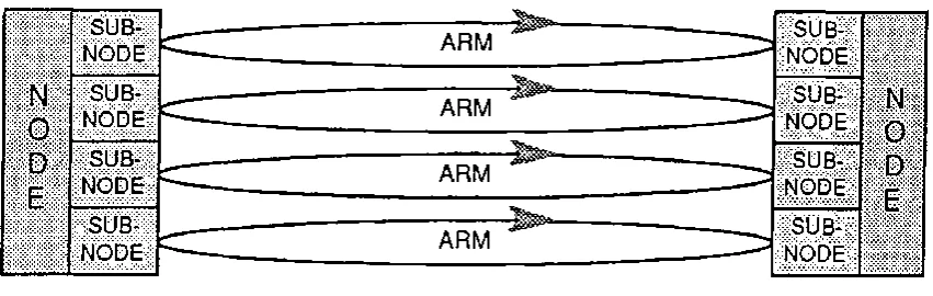
2.3 The Orwell Torus
To enable Orwell rings to carry very large volumes of traffic the protocol has been
designed to allow a number of rings to be able to operate together, in parallel, and in
a synchronous manner: such a network is known as an Orwell Torus. Figure 3
shows
Figure 3: Torus of Orwell rings
an example of the torus, each individual loop of glass fibre between the nodes is
known as an Arm. The slots on individual arms are staggered so that ordering is
always preserved between slots on different arms of the torus (there are fairly strict
limits in the different fibre lengths that can be used on each arm). All of the rings
operate using a single d-counter, and a cell awaiting access to the torus is placed
in the first slot to become available; resets operate similarly, a reset on one ring
causing all the rings to be reset [9, 10].
Another advantage of the torus is the increase in reliability due to replication in the
network: if a single ring or sub-node fails then the system can simply carry on
operating at a reduced capacity; careful isolation between the node controller and
the sub-nodes can ensure that, should a node controller fail, the sub-nodes can
become transparent repeaters that take no further action on the torus other than to
forward slots.
2.4 Calculation of the d-value
In practice, traffic on an Orwell ring is divided into three classes, each at a different
and signalling traffic) can be given a higher priority. To ensure that all classes of
traffic still have some access to the network, the d-counter is also divided into
three counters, each representing one of the priority levels. When a cell arrives at
a node and is waiting for access to the ring it is placed in the queue appropriate
to its priority: when an empty slot is received the cell in the highest priority queue
that still has an unused d-allocation is selected and the appropriate counter adjusted
downwards; since the node as a whole is only barred from further access when all of
the queues are either idle or blocked all classes of traffic are guaranteed some access
to the ring during each reset interval, but delay sensitive services always get the
highest priority.
In order to bound the delay at a ring within acceptable limits the amount of traffic
carried has to be carefully controlled. There is no need, however, for a centralized
call-control mechanism since the total load being carried by the ring can be
determined from the reset rate provided that the ring has time to reach equilibrium
between call attempts: calls are only accepted if the reset rate is sufficiently low to
guarantee sufficient capacity for that call. For each new call the d-allocation is
adjusted accordingly; there are several methods available for determining what value
this should be and two possible methods are given here. The static allocation scheme
bases the calculation on the arrival rate of cells for that type of call, A, and the
maximum permissible interval between resets (Maximum Reset Interval, M.R.I.):
for each call,
(16)
and the d-allocation for a single priority is the sum of all the appropriate 8d's rounded
to the next largest integer; for V.B.R. calls, A is not necessarily the mean cell arrival
rate, but may be slightly higher to allow for statistical variation. In the dynamic
allocation scheme the d-allocation is adjusted based upon whether it was fully
used over the preceding reset intervals: if the full d-allocation were used over, say,
the preceding three intervals then the allocation is increased by one; if it were not
fully used in each of the intervals then its value is decreased by one. This is
the lowest priority queue can either be a fixed constant or be adjusted to represent the
difference between the maximum for the ring and the amount claimed by the other
queues.
Computer-data traffic, which is usually the service with the greatest delay tolerance is
normally allocated to the third queue which commonly has a permanent d-allocation
of 1 or 2. This ensures that while the reset rate is high a large proportion of the ring
bandwidth is available for such services, but as the reset rate drops (i.e. occur less
often) then such services are 'throttled back' and priority given to those that are delay
sensitive; some bandwidth, however, is always guaranteed.
3.
First model
3.1 Algorithm
This model emulates the behaviour of the ring by using an array filled with random
node numbers to represent the searching action of slots. The algorithm is
reproduced below.
Each node, i, on an Orwell ring has an amount of bandwidth allocated to it that is
stored in its 'd-counter', di; di being proportional to the number of calls being carried.
Then, assuming that there are N nodes on the ring, let
(17)
An array, Q, of size S is then filled using the following algorithm:
for each node, i
repeat di times
j := random number between 1 and S
if Qj is filled then
increment j until Qj is unfilled
fi
Qj := i
end
Once the array has been filled, it is scanned in order using the following algorithm.
This simulates the random manner in which the slots are accessed by the nodes
waiting on the loop. A complete pass of the array with no cells switched represents a
trial slot traversing the entire loop without being claimed and a reset occurring.
j := 1
repeat
if Qj filled then
if cell waiting on node Qj then
switch cell
Qj:= empty
fi
fi
j := (j mod S) + 1
until All Qz are empty or one pass of j with no cells switched
Since, on average, a slot is filled by a cell for one half of one ring rotation, and
because the slot cannot be filled again until the slot has reached the node after
the one at which it was released, then the slot is in use for, on average, 1 + N /2
nodes and the proportion of each ring rotation for which the slot is in use is
(18)
If there are K slots on each ring in the torus, and R rings, there will be a total of
KR slots. If the slot rotation time is t seconds, then the number of cells that are
carried in one second is
(19)
giving r as the mean time between each cell being switched.
To take account of the fact that the first time the ring is found to be idle would
probably not cause a reset to occur, the algorithm was implemented in a slightly
modified manner to permit this feature to be incorporated: the searching algorithm
occurred; the ring was not reset until the status counter had incremented to a
pre-calculated limit (this calculation being based on the minimum time that a real ring
takes to reset when completely idle, i.e. one slot rotation time plus the time required
to get to following node). Several algorithms were used for determining how the
status counter should be incremented. The first was to reset the status counter to zero
each time a cell was carried; the second to allow the counter to increment to a certain
value each time a cell was switched, and then to pause it at this value until the ring
became idle before letting it increment up to the limit; the third was simply to allow
the status counter to increment up to a fixed distance from the limit and pause it at this
level until the ring became idle.
Initially the delay between switching each cell was maintained as the constant, T.
3.2 Results
Simulations were performed on an eight node network connected by a 140Mbit/s ring.
Only voice traffic was offered to the ring, and the auto-reset mechanism within
Orwell was disabled. The cells used were of a different size to the now adopted
values of 45 octets body and 5 octets header, at 16 octets body and 5 octets
header: these values were maintained throughout this series of simulations so that
comparisons could be made. The mean call holding time was set to a tenth of a
second.
From these values the theoretical capacity of the ring can be calculated. The
usable bandwidth, B' (efficiency) of the ring is given by
(20)
where, B is the bandwidth of the ring, lc is the size of the cell and ls is the size
of the slot. Since each cell uses a slot for an average of (1 + N/2)/ N of a rotation,
then the carrying bandwidth, B", is given by
Since each voice call requires a bandwidth, Bv, of 64 Kbits/s (the simulator only
generates traffic in one direction), then the call capacity, C of the ring is
(22)
This value is an upper bound on the carrying capacity of the ring, and it ignores the
reduction in available bandwidth caused by the trial and reset slots.
For the ring simulated in these experiments, therefore, the maximum traffic capacity of the
ring is equivalent to 2,666 calls. This is an absolute maximum for the ring; n practice the
load control mechanism would limit the number of calls carried to somewhat less than this in
order to hold the queueing delay within acceptable bounds.
Initial runs on the algorithm were done over a simulated time of 0.1 seconds after a warm-up
period of 0.1 seconds; whilst these times are very short, and it is clear that the ring has not
been given time to reach equilibrium, it is the relative performance of the simplified model
when compared with the full model of the protocol that is of interest. The first set of
simulations were performed using the 'backing off' technique for the status of the loop,
holding the status counter at two less than the maximum value; intuitively this can be
justified in that as a loaded ring approaches a reset, there are some empty slots circulating
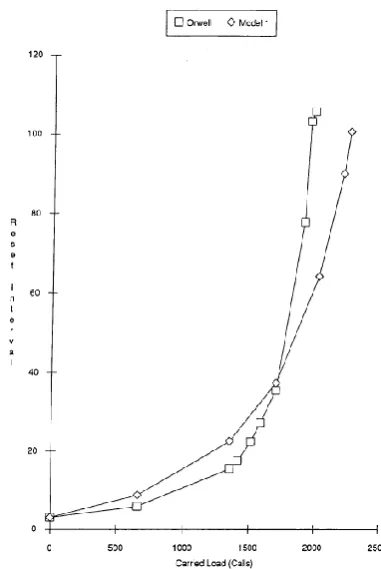
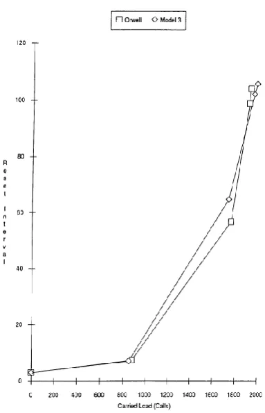
around the ring, whilst some slots are still carrying data. Figure 4 shows the mean reset
interval as a function of carried load; it is clear from these graphs that the model has a
significantly lower mean, enabling it to accept a much higher number of calls than the full
protocol. Figure 5 shows the mean of the queue lengths as a function of carried load, and
again it is clear that the amount of queueing caused by the model is significantly lower (the
queues in Orwell are approximately a factor of ten longer).
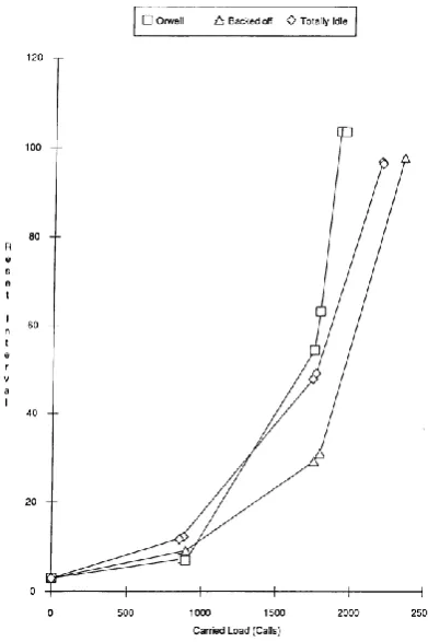
The 'backing off' of the status counter appeared to be causing the ring to reset more
rapidly than was desired, so some simulations were performed at the other extreme, i.e. the
Figure 4: Graph showing the mean reset interval (in µs) against carried load for Orwell and the first model using 'backed off' resets
Figure 5: Graph showing the mean queue length against carried load for Orwell and the first model using 'backed off' resets
6 and 7 show the reset behaviour and queueing behaviour of this variant. They show
that for low and medium loads, the reset interval is larger than that of Orwell, while for
high loads the ring is still resetting too rapidly. The queueing can be seen to be significantly
closer than for the 'backed off' model, but the queues are only of identical length at the
point where the reset behaviour is least accurate.
In an attempt to match the queue lengths more accurately, it was decided to introduce a
random element into the delay between switching cells, the justifica tion being taken from the
fact that an M/D/1 queueing system has a mean queue length half that of an M/M/1 system.
Obviously the service time on Orwell can- not be a negative exponential, since the cell is of
fixed size and the propagation delay around the ring (part of the service time in this model)
has an upper bound of one rotation delay. However, as a first approximation to the service
characteristic, a negative exponential service time was used, since this should form an upper
bound on the degree of randomness of the service time.
The results of runs using the exponential service characteristic are shown in figures 8 and 9. It
can be seen that the effect is to reduce the reset interval slightly at all loads, but has only
affected the queueing at low loads; at high loads the amount of queueing is unaffected.
The results correlation obtained thus far, was fairly poor, particularly when it is
considered that the reset interval determines the maximum load that the ring can accept.
In addition to this, the model was taking significantly longer to execute than simulations
of the full protocol, and since the carried loads at certain offered loads were similar this
could only be explained as the result of using a poor algorithm. It was realized that the
array filling and searching was very inefficient; in particular, at low loads a large array was
being filled with random numbers and then not used because the ring was idle. In addition,
the searching algorithm for the array was inefficient: to discover that the ring was in fact
Figure 6: Graph showing the mean reset interval (in µs) against carried load for Orwell and the first model using 'totally idle' resets
Figure 8: Graph showing the mean reset interval (in µs) against carried load for Orwell and the first model with negative exponential service time and 'totally idle' resets
'totally idle' resets
and the first model with negative exponential service time and 'totally idle' resets
array, regardless of whether the indicated node had already been checked. A new algorithm
was developed in an attempt to rectify these problems.
4.
Second Model
4.1 Algorithm
Since the first algorithm had been proved to be inefficient partly due to generating too many
random numbers, an approach that avoided the redundant generation of random numbers
was required, in addition it was necessary to avoid checking a node several times when
trying to decide whether it was idle.
Both of these problems were avoided by using the algorithm below; in addition the overhead
at each reset is reduced to that of resetting the no4e itself.
reset ring
while ring is not idle
generate a random node number
while (node is paused or idle) and there are unchecked nodes check the next node
endwhile
if we have a cell to switch
switch the cell
next status value else
next status value
fi
wait for delay
endwhile
The 'next status value' is calculated by one of the methods mentioned in the first model.
Switching the cell now also involves updating the d-counter at the node, a process that was
4.2 Results
The results for the above algorithm, using simulation runs of 1.0 seconds after 0.5
seconds warm-up are shown in figures 10 and 11. These results indicate that the behaviour
of the second model is almost identical to that of the first, i.e. the ring was accepting a far
greater load than the Orwell protocol. This discrepancy can be explained by inspecting the
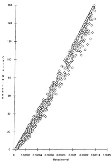
number of cells switched as a function of the size of the reset interval, figures 12 and 13.
From these graphs it becomes clear that the service time of Orwell cannot be a
constant, but must be a function of the offered load: an interesting, and advantageous,
feature of the protocol is that this function is such that the service rate for the ring
increases as the load increases; this should be compared with a C.S.M.A./C.D. type protocol
(for example, Ethernet) where the opposite occurs, leading the network to become less
efficient at high loads.
Having noted that the service rate of the ring is not a constant, the explanation 1s readily
apparent: in Orwell the slots circulating around the ring have two phases. In the first, the
slot is carrying a cell and the distribution of this phase is as noted before. In the second
phase, an empty slot is searching for a load, and it is the distribution of this phase that is not a
constant, but a function of the number of active nodes. Therefore, if accurate behaviour is to
be obtained, the model needs to be modified to take this search period into account.
5.
Third Model
5.1 Algorithm
The previous two models have both been characterized by having a fixed average for the
service time on the ring. In order to enable a load dependent service time to be
implemented a couple of changes had to be made to the simulation program. These changes
entailed keeping a record of the number of nodes that had cells ready for switching (and
that were not in the paused state); alterations to the simulator entailed modifying the
code so that all changes to the status of a node were performed by a single sub-routine.
To take advantage of the knowledge of the state of activity of the ring thereby obtained, one
small approximation is needed, namely that the delay before switching the following cell can
algorithm will slightly under-estimate the activity on the ring since nodes may well become
active while a cell is being carried).
Figure 11: Graph showing the mean queue length against carried load for Orwell and the second model
Figure 13: Graph showing the number of cells switched as a function of the size of reset interval for the Orwell protocol
In addition to this a further simplification can now be made to the model without any loss of
accuracy: if all the nodes are either idle or paused, then there is no need to do any
inspections on the ring and, hence, time can be saved.
reset ring
while ring is not idle
if there are active nodes
generate a random node number
while (node is paused or idle) and there are unchecked nodes check the next node
endwhile
switch the cell
next status value
calculate delay based on number of active nodes
else
calculate delay when ring is idle next status value
fi
An exact value for the average hold time as a function of the number of active nodes is very
difficult to calculate. The following values were used to 'test out' the model, and seem to
give reasonable results. When the ring is totally idle, the delay is simply the time it takes
for a slot to go around the ring, divided by the number of slots, t/KR. ·when a slot is
seized it is held on average for half a rotation, so for KR slots the average hold time is
t/2KR (cf. equation 19, the fact that the slot cannot be seized until the following node is
now accounted for by the search period). The search period is proportional to the number
of idle nodes, and any particular slot will, on average, be half way to that node, giving
the proportion of a rotation spent searching as 1- a/ N if there are a active nodes on the
ring. The total delay is simply the sum of these two parts,
(23)
5.2 Results
The model was simulated over a period of 1.0 seconds after a warm-up time of 0.5
seconds, using 'totally idle' resets. Figure 14 shows that the reset interval is now much more
closely matched to the original protocol and, in particular, the maximum load is almost
identical. Figure 15 shows that, while queueing is now much more closely matched, there is
still a factor of two difference on the results obtained so far.
Finally, figure 16 shows the total processing requirements for simulating the Orwell protocol
and the third model (warm-up time and running time); it can be seen that, for any particular
carried load, the model is marginally faster (though for very high offered loads the fact that
the model still accepts slightly fewer calls means that the total simulation time is likely to
be longer).
To assess in detail the contribution to simulation time added by the nature of the Orwell
protocol more simulations are required at very low loads. It is notable that the simulation time
requirement is not linear with respect to the carried load, but increases significantly as the load
attempts.
Figure 14: Graph showing the mean reset interval (in μS) against carried load for Orwell
Figure 15: Graph showing the mean queue length against carried load for Orwell and the third model using 'totally idle' resets
Figure 16: Graph showing the processor requirements on a Sun 3/50 work-station,in CPU seconds, as a function of carried load for the Orwell model and the third model
6. Summary
The pressing need to try and reduce the amount of simulation time required for simulating
large networks has led to several models being created that simplified the details of the
Orwell protocol, whilst still trying to maintain its outward functionality. It was found that the
behaviour of the ring had two contributory factors: a service time, during which the slots were
carrying cells around the ring; and a search time, while they were looking for new cells to
carry. The service time had a constant average, while the search time was a function of the
instantaneous load carried by the ring.A detailed insight has been obtained into the behaviour
of the Orwell protocol and, in addition, some reductions in the simulation time required have
been achieved. However, it was decided that the model could not be incorporated into the
References
1. R. J. Lipton and D. W. Mizell, "Time Warp vs. Chandy-Misra: A Worst-case
Comparison," in Distributed Simulation, pp. 137-143, January 1990.
2. W. Cai and S. J. Turner, "An algorithm for Distributed Discrete-event Simulation - The
"Carrier Null Message" Approach," in Distributed Simulation, pp. 3-8, January 1990.
3. R. C. De Vries, "Reducing Null Messages in Misra's Distributed Discrete Event
Simulation Method," IEEE Transactions on Software Engineering, vol. 16, pp.
82-91, January 1990.
4. S. Bellenot, "Global Virtual Time Algorithms," in Distributed Simulation, pp.
122-127, January 1990.
5. D. Baezner, G. Lumow, and B. W. Unger, "Sim++: The Transition to Distributed
Simulation," in Distributed Simulation, pp. 211-218, January 1990.
6. N. J. Bailey, A. Purvis, I. W. Bowler, and P. D. Manning, "An Highly Parallel
Architecture for Real-time Music Synthesis and Digital Signal Processing Application,"
in Proceedings of the International Music Conference, Glasgow, 1990.
7. J. Dupraz and M. De Prycker, "Principles and Benefits of the Asynchronous Transfer
Mode," Electrical Communication, vol. 64, no. 2/3, pp. 116-123, 1990.
8. S. J. Nichols, Simulation and Analysis of Adaptive Routeing and Flow Control in Wide
Area Communication Networks. PhD thesis, University of Durham, March 1990.
9. D. P. Helmbold and C. E. McDowell, "Modeling Speedup (n) Greater than n," IEEE
Transactions on Parallel and Distributed Systems, vol. 1, pp. 250- 256, April 1990.
10. J. Chauhan, T. King, and A. C. Micallef, Specification of the Orwell Protocol. British
Telecom Research Laboratories, Martlesham Heath, Ipswich, Suffolk, UK. IP5 7RE,
May 1990. Revision C.1(05/90).
11. P. W. Glynn and P. Heidelburger, "Analysis of Parallel Replicated Simulations Under a
Completion Time Constraint," A.C.M. Transactions on Modeling and Computer
12. J. Appleton, "Traffic Shaping in Asynchronous Transfer Mode Networks," in
Proceedings of the Eighth U.K. Teletraffic Symposium, pp. 19/1-19/4, April 1991.
13. J. R. Chen and P. Mars, "Adaptive ATM Call Access Control Using Learning
Algorithms," in Proceedings of the Eighth U.K. Teletraffic Symposium, pp. 18/1-18/5,
April 1991.
14. N. J. Bailey, A. Purvis, I. W. Bowler, and P. D. Manning, "Some Obser- vations on
Hierarchichal, Multiple-Intruction-Multiple-Data Computers," in Proceedings of
Euromicro, Vienna, September 1991.
15. N. J. Bailey, On the Synthesis and Processing of High Quality Audio Signals by