Frequency Diverse Array Using Butler Matrix for Secure Wireless
Communications
Shaddrack Y. Nusenu*, Hui Chen, Wen-Qin Wang,
Shilong Ji, and Obour A. K. Opuni-Boachie
Abstract—An antenna array system configured to offer directional dependent modulation has the
capability to prevent eavesdroppers’ attacks, thereby enhancing the security level of data transmission. In this paper, we propose artificial-noise-aided directional modulation transmitter utilizing a 4×4 Butler matrix with a four-element 2-D (i.e., range and angle) frequency diverse array (FDA) antenna to achieve secure transmissions, which outperforms the 1-D (i.e., angle) phased array scheme. The proposed scheme utilizes FDA Butler matrix excited by information data and injected artificial noise interference which radiates along all directions except the main information data direction. Thus, the radiation pattern during a particular transmission period will be range-angle dependent. The proposed scheme is evaluated by using constellation points inIQ space, bit error probability (BER), and secrecy capacity. Simulation results demonstrate that: 1) our scheme scrambles the constellation points along undesired direction(s) in both amplitude and phase, while preserving a clear constellation points along the pre-specified direction(s); 2) the scheme achieves better BER and secrecy capacity than that of the phased array based directional modulation scheme and other existing scheme; 3) the scheme significantly improves security performance especially in the range dimension.
1. INTRODUCTION
Directional modulation (DM) is a promising physical-layer security technique for wireless communications [1]. The fundamental concept behind DM implies that the modulation takes place at antenna level, instead of at baseband. In doing so, a certain constellation with a low error rate can be achieved along pre-specified desired direction(s), while the constellations will be distorted in other undesired directions to produce high error rate. In [2, 3], a phased-array antenna based DM was proposed for secure communications. A similar approach was adopted in [4], where a 4×4 Butler matrix [5–8] was used to scramble the radiation pattern in sidelobes by introducing artificial interferences in all other directions apart from the desired direction. Recently, [9] developed a new 4×4 Butler matrix without phase shifters and had only couplers with−45◦ and −90◦ phase difference.
On the other hand, frequency diverse array (FDA) has been widely investigated in radar field [10]. Recently, FDA has been a very attractive array for DM secure wireless communications [11–15] compared to that of the phased array antenna. Using a phased array antenna for DM and assuming realistic scenario, an eavesdropper could be located along the same specified direction as the intended user, while in an FDA antenna based DM, this scenario is different (i.e., intended user and eavesdropper may be positioned in the same direction but distinct ranges). The main difference between FDA and phased-array is the small frequency increment used across the array elements. This frequency increment makes the array beampattern to change as a function of the range, angle and time [10] and [16]. In
Received 13 October 2017, Accepted 10 November 2017, Scheduled 14 January 2018
* Corresponding author: Shaddrack Yaw Nusenu ([email protected]).
practical array systems, we are solely motivated by the advantages of both FDA and Butler matrix, in addition to DM characteristics from a more practical point of view.
Therefore, in this paper, we utilize DM property based on FDA and a 4×4 Butler matrix [9] to improve physical-layer security of wireless communications. The following summarizes the contributions of this work:
• Artificial-noise-aided FDA and a 4×4 Butler matrix [9] have been designed to produce 4-ary constellation points which achieves secure communications in 2-D (i.e., range and angle dimensions) and can be utilized in wireless communication systems using an orthogonal beamforming network.
• We derive an expression for bit error rate and analyze the secrecy capacity of the proposed scheme. Due to the advantages of both FDA and 4×4 Butler matrix, this proposed scheme significantly outperformed the phased array DM and [4] in terms of BER and secrecy capacity.
The rest of this paper is organized as follows. Section 2 proposes the DM transmitter by jointly utilizing the Butler matrix and FDA antenna. Section 3 presents FDA Butler matrix with artificial noise. Section 4 evaluates the performance analysis in terms of bit error rate (BER) and secrecy capacity. Next, numerical results are provided in Section 5, and finally, this paper is concluded in Section 6.
2. FDA DM TRANSMITTER USING BUTLER MATRIX SCHEME
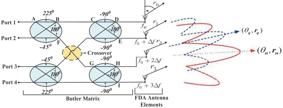
Figure 1 shows a notional block diagram of two-dimensional (2-D) (i.e., range and angle) half wavelength spaced FDA antenna-based DM using a 4×4 Butler matrix for secure communications. We employ four FDA elements with carrier frequencies connected at the outport of a 4×4 Butler matrix, namely, f0,
f0+ Δf,f0+ 2Δf and f0+ 3Δf, respectively, where f0 is the carrier frequency and Δf the frequency
increment across the array element. The basic principle is that when Port 1 is excited, it goes through the signal path, A-B-C-D to f0, with phase shift of 135◦. Similarly, a phase shift of 90◦ is obtained
between Port 1 andf0+ Δf using the signal path A-B-C-E and so forth. Note that since we employ a
4×4 Butler matrix, the FDA elements have been set to four. The phase differences of a 4×4 Butler matrix are±45◦ for the output ports 1 and 4, and±135◦ for the output ports 2 and 3, respectively [17].
0
r
•
1 r
2 r
3
r
Butler Matrix FDA Antenna Elements Crossover
Port 1
Port 2
Port 3
Port 4
A B
F
C D
E
G H
I 0
180
0
180
0
-180
0
-180
0
-90
0
-90
0
-90
0
-90
0
225
0
225
0
-45
0
-45
0
f fffffff
0 2
f 2 fffff
0 3
f 3 ffffff
0
f
( , )
θ
q rq( , )
θ
nr
nFigure 1. FDA using a 4×4 Butler Matrix for secure communications.
In this paper, we adopt a uniform linear frequency increment FDA antenna as depicted in Fig. 1. The frequency radiated from themth FDA element can be given by
And the steering vector can be approximately written as [16]
u(θ, r) =
1 e−j
2πf 0dsin(θ)
c0 −2 π·Δf·r
c0
. . . e−j
2πf
0(N−1)dsin(θ)
c0 −
2π(N−1)Δf·r c0
(2)
whereθdenotes the angle, andr is the range in far field. The transfer function from thenth input port to themth output port of the 4×4 Butler matrix is given as [4]
Tmn = √1
Ne −j2π
N(m− N+1
2 )(n−N+12 ), m, n= 1,2, . . . , N. (3)
To describe the linkage between the radiation pattern and digital information symbol synthesis, we consider the array factor for FDA N-element given by
F(θ, r;t) =
N
m=1
Amej
(m−N+1
2 )πsinθ−2πcΔ0f r+βm
(4)
where Am is the amplitude excitation, and βm is the phase difference of a 4×4 Butler matrix. For a
specific time, t and location (θ, r), Eq. (5) is a complex digital symbol with the magnitude and phase that can be observed as a constellation point on the IQdiagram [2]. For simplicity, we assume line-of-sight (LOS) communications in L directions, namely, (θl, rl), l = 1,2, . . . , L. The information symbols
at a specific time,t, can be formulated as ⎡
⎣ I
(t, θ1, r1)
.. .
I(t, θL, rL)
⎤ ⎦=
⎡ ⎣ z1
(θ1, r1) . . . zN(θ1, r1)
..
. . . . ...
z1(θL, rL) . . . zN(θL, rL)
⎤ ⎦
⎡ ⎣ s1
(t) .. .
sN(t)
⎤
⎦ (5)
where zm(θl, rl) is the radiation field for the mth element in thelth range-angle position, and sm(t) is
the signal excitation for the mth element which corresponds to:
sm(t) =Amejβm (6)
Now, the far-field radiation pattern of thenth Butler matrix input port excitation can be obtained in Eq. (7) by plugging in Eq. (3) and Eq. (6), respectively.
Fn(θ, r) = N
m=1
Amejβm
√
N e
−j2π N(m−
N+1
2 )(n−N2+1)
ej
(m−N+1
2 )πsin(θ)−2πcΔ0f r
(7)
This implies that the main beam pointing direction depends on not only the angle θ but also the range r and frequency increment Δf. From Eq. (7), the beampattern peak corresponds to
2π N
m− N+ 1
2 n−
N+ 1 2
=π
m−N + 1
2
sinθ− 2Δf r c0
(8)
And the corresponding instantaneous main beam pointing direction angleθn can be calculated by
θn= sin−1
2n−N −1
N +
4Δf rn
c0(2m−N −1)
(9)
Therefore, the instantaneous main beam pointing direction angle θn depends on both the range
rn and the frequency increment Δf, whose characteristics can be exploited for directional secure communications.
Similarly, by replacing nin Eq. (7) and Eq. (9), with q, the far-fieldFq(θ, r) generated by theqth
Butler matrix input port excitation with the instantaneous main beam pointing direction angle θq can
be acquired. It is easy to verify that Fn(θq) = 0 when n = q. This implies that the Fq(θ, r)’s main
beam is projected along the null radiation direction ofFn(θ, r). It should be noted that because of the
beam orthogonality property of a Butler matrix, we can have Fn(θ, r)’s main beam and Fq(θ, r)’s null
3. FDA BUTLER MATRIX WITH ARTIFICIAL NOISE
When employing FDA with a Butler matrix as a beamforming network, the signal, driving thenth input port of a Butler matrix, is radiated into free space with the maximum power projected along the desired directionθn. Since the same well formatted signal also exists at other locations, even though power is suppressed, eavesdroppers positioned along these directions still can recover the information data by means of more sensitive receivers. In order for the system to achieve low probability of interception (LPI), we introduce artificial noise interference which can be injected into the Butler matrix at ports other than thenth input port, as illustrated in Fig. 1. By taking advantage of the beam orthogonality property described earlier in Section 2, we arrange that the artificial noise signal is radiated with a null power direction along θn. It means that the information transmitted along the desired direction θn is
not affected, and simultaneously, the information leaked into other locations is seriously affected by the artificial noise.
In the context of physical layer security, beamforming with artificial noise has been extensively utilized because of several advantages [18, 19]. Hence, we resort to artificial noise secure transmission in FDA Butler matrix. Now, consider beamforming with artificial noise, the signal transmitted can be written as [11]
ˆ
s=αPtvx+(1−α)Ptu (10)
where x denotes the symbol chosen from the complex signal constellation (i.e., QPSK modulation scheme), Pt the transmitted power, αthe parameter that determines the power allocation between the
desired information and artificial noise, v the beamforming vector for the desired information, and u
the artificial noise vector. To maximize the signal to noise ratio (SNR) at the desired receiver, v is described as
v=a(θn) (11)
where (θn) denotes the instantaneous main beam pointing direction at the transmitter to the desired receiver. The artificial noise vectoru should lie in the null space ofa(θn) (i.e., a∗(θn)u= 0) in order to avoid interference to the desired receiver. Therefore, the artificial noise vector u is given as [20]
u= (IN −a(θn)a
∗(θ
n))k
(IN −a(θn)a∗(θn))k (12)
where k (i.e., k ∼ CN(0,IN)) consists of N i.i.d. circularly-symmetric complex Gaussian random variables with zero-mean and unit-variance, and (·)∗ denotes the conjugate operator.
According to Eq. (10), the received signal at the desired receiver can be expressed as
y(θn) = a∗(θn) ˆs+wn (13)
= αPta∗(θn)vx+wn (14)
where wn (i.e, wn ∼ CN(0, σ2n)) denotes the additive white Gaussian noise (AWGN). It can be seen from Eq. (14) that the desired receiver can restore the original signalxfrom the transmitter easily. On the other hand, we assume that the eavesdropper receiver cannot obtain the original signalx. Following Eq. (14), the SNR at the desired receiver is written as
ϕn =αPσ2t
n (15)
In alike manner, the received signal at eavesdropper receiver is given as
y(θq) = a∗(θq) ˆs+wq (16)
= αPta∗(θq)a(θn)x+(1−α)Pta∗(θq)u+wq (17) where wq (i.e., wq ∼ CN(0, σq2)) denotes the additive white Gaussian noise (AWGN). Note that, as
per Eq. (17), the parameter √Pta∗(θq)a(θn) distorts the amplitude and phase of the received signal at
eavesdropper receiver. Employing Eq. (17), the SNR at eavesdropper receiver can be given as
ϕq= ϕn|a
∗(θq)a(θn)|2
(1−α) Pt
σn2|a∗(θq)u|2+ Ψ
(18)
where Ψ =σ2
4. PERFORMANCE METRIC
4.1. Bit Error Rate (BER) Analysis
We employ BER metric to evaluate the characteristics performance of our proposed scheme. The exact symbol error probability of QPSK modulation can be expressed as [3, 21].
P =erf c
ρ
2
−1
4erf c
2 ρ 2 (19)
whereρ= Es
No, anderf c(x) = 2 √ π ∞ x e
−t2
dt is defined as the complementary error function. Accordingly, the final form of symbol error probability for the proposed scheme can be derived as
Pe(θ, r) = N m=1 ⎧ ⎪ ⎪ ⎪ ⎪ ⎪ ⎪ ⎨ ⎪ ⎪ ⎪ ⎪ ⎪ ⎪ ⎩ erf c ⎛ ⎝ ρ 2
(Tmnsm(t))ej
(m−N+1
2 )πsinθ−2πcΔ0f r
2 ⎞ ⎠
−1
4erf c
2 ⎛ ⎝ ρ 2
(Tmnsm(t))ej
(m−N+1
2 )πsinθ−2πcΔ0f r
2 ⎞ ⎠ ⎫ ⎪ ⎪ ⎪ ⎪ ⎪ ⎪ ⎬ ⎪ ⎪ ⎪ ⎪ ⎪ ⎪ ⎭ (20)
It can be recognized that the probability of error depends on the receiver direction θ, range r and frequency increment Δf.
4.2. Secrecy Capacity Analysis
In this paper, we consider multiple-input single-output (MISO) Gaussian wiretap channel [22]. We assume that the transmitter is equipped with N antennas, the desired receiver (D) equipped with a single antenna, and eavesdropper receiver (E) equipped with a single antenna. We assume that the position of the desired receiver D, denoted by (θD, rD), is known at the transmitter side, while that of eavesdropper receiverE, denoted by (θE, rE), is unknown at the transmitter side. The secrecy capacity
Csis defined as [0, CD−CE]+, whereCD denotes the capacity atD, andCE is the capacity atE. The operator [x]+ returns zero provided that x is negative, elsex is returned. Herein, we assume non-zero capacity scenario, henceCs is given as
Cs= B
Nlog2
⎡ ⎢ ⎢ ⎢ ⎢ ⎢ ⎣
1 +ρ
N
m=1
Tmnsm(t)ej
(m−N+1
2 )πsinθD−2πΔc0f rD
1 +ρ
N
m=1
Tmnsm(t)ej
(m−N+1
2 )πsinθE−2πΔcf rE
0 ⎤ ⎥ ⎥ ⎥ ⎥ ⎥ ⎦ (21)
whereB denotes the channel bandwidth (Hz).
5. SIMULATION RESULTS
In this section, we evaluate the performance analysis of the proposed scheme with the phased-array DM and [4] schemes as benchmarks. We consider a uniform linear FDA array with carrier frequency
f0 = 10 GHz and array element of N = 4. The artificial noise level power is assumed to be 10 dB (i.e.,
lower than that of the information data stream to be transmitted). In addition, we assume Gray coding in this paper; therefore, the symbols should lie in the first to the fourth quadrants in IQ space along the pre-specified direction as follows: “11”, “01”, “00”, and “10”, respectively.
0 20 40 60 80 100 120 140 160 180 -25
-20 -15 -10 -5 0 5 10 15
Angle [θ]
Magnitude [dB]
input port 3 input port 1 input port 4 input port 2
0.5 0.6 0.7 0.8 0.9 1 1.1 1.2 1.3 1.4 1.5
x 104 -25
-20 -15 -10 -5 0 5 10 15
Range [m]
Magnitude [dB]
input port 1 input port 3 input port 2 input port 4
(a) (b)
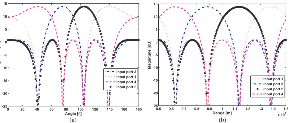
Figure 2. 4×4 Butler matrix input ports excited radiation power pattern when Δf = 30 kHz is
adopted, (a) in angle dimension, (b) in range dimension.
The information data stream to be transmitted with QPSK modulation scheme is injected into the FDA Butler matrix, specifically, at the second input port (104◦,11.2 km), while artificial interference is also allowed to excite the remaining ports. In order to visualize the impact introduced by the injected artificial noise, Fig. 3 shows IQ constellation diagrams detected along the desired direction (104◦,11.2 km) and the eavesdropper directions, for example, (30◦,7 km), (60◦,9 km), and (150◦,12 km), respectively. From Fig. 3(a), the QPSK signal constellation at the desired receiver position can be easily demodulated. However, in Figs. 3(b)–(d) it can be observed that for the distinct range and different angle positions, the QPSK signal constellation has been significantly distorted, which makes the eavesdroppers need to pay extra effort to correctly demodulate the transmitted information. Furthermore, the constant phase artificial noise interference in Eq. (17) does alter the distribution of the constellation symbols, hence improving the security level in the system.
We examine the BER performance in both angle and range dimensions. The results are compared with that of phased array DM and [4]. Herein, we consider a data stream with 106 random QPSK
-2.5 -2 -1.5 -1 -0.5 0 0.5 1 1.5 2 2.5 -2.5
-2 -1.5 -1 -0.5 0 0.5 1 1.5 2 2.5
In-Phase
Quadrature
Symbol ’10’ Symbol ’01’ Symbol ’00’ Symbol ’11’
-2.5 -2 -1.5 -1 -0.5 0 0.5 1 1.5 2 2.5 -2.5
-2 -1.5 -1 -0.5 0 0.5 1 1.5 2 2.5
In-Phase
Quadrature
Symbol ’10’ Symbol ’01’ Symbol ’00’ Symbol ’11’
-2.5 -2 -1.5 -1 -0.5 0 0.5 1 1.5 2 2.5 -2.5
-2 -1.5 -1 -0.5 0 0.5 1 1.5 2 2.5
In-Phase
Quadrature
Symbol ’10’ Symbol ’01’ Symbol ’00’ Symbol ’11’
-2.5 -2 -1.5 -1 -0.5 0 0.5 1 1.5 2 2.5 -2.5
-2 -1.5 -1 -0.5 0 0.5 1 1.5 2 2.5
In-Phase
Quadrature
Symbol ’10’ Symbol ’01’ Symbol ’00’ Symbol ’11’
(c) (d)
Figure 3. Illustration of proposed scheme QPSK constellation pattern at intended direction and
eavesdropper directions when Δf = 100 Hz is adopted, (a) intended direction (104◦,11.2 km): Eavesdropper directions, (b) (30◦,7 km), (c) (60◦,9 km) and (d) (150◦,12 km).
0.8 0.85 0.9 0.95 1 1.05 1.1 1.15 1.2 x 10⁴ 10−5
10−4 10−3 10−2 10−1 100
Range [km]
BER
Proposed scheme Ref [4]
DM − Phased−array
90 100 110 120 130 140 150
10−5 10−4 10−3 10−2 10−1 100
Angle [T]
BER
DM − Phased−array Ref [4]
Proposed scheme
(a) (b)
Figure 4. Comparisons of BER performances when SNR = 6 dB is assumed, (a) in angle dimension,
(b) in range dimension.
2 4 6 8 10 12 14 16 18 20 −1
0 1 2 3 4 5 6 7 8 9 10
SNR [dB]
Secrecy Capacity
Proposed scheme Ref [4]
DM − Phased array
Figure 5. Comparisons of secrecy capacities performance of proposed scheme, phased-array DM and [4],
respectively.
employing an orthogonal beamforming network.
Finally, Fig. 5 shows secrecy capacities of the proposed scheme, phased array DM and [4], respectively. As expected, it is evident that the secrecy capacity of the phased array DM is zero. This is because the eavesdropper receiver may exactly be located in the desired direction as the legitimate user. In this scenario, the phased-array DM cannot guarantee secure transmission for the legitimate user, because the phased-array DM can only distort signals at the directions that are distinct from the desired receiver position. Furthermore, [4] secrecy capacity is lower than that of the proposed scheme, because the latter utilizes phased-array with interference signal injected into the Butler matrix. The former shows superiority due to the employment of FDA which has range and angle capabilities together with artificial noise injected into the Butler matrix.
6. CONCLUSION
In this paper, we propose Butler matrix with FDA inspired array-level DM transmitter aided by artificial noise which has the capability to secure wireless communication in free space along the pre-specified range and angle location at the physical-layer. Injected artificial noise interference radiates along all directions apart from the main information direction, and hence submerged the information leaked into other locations so as to prevent the eavesdroppers from signal demodulation via interception. The proposed scheme was evaluated using constellation points (QPSK transmission), BER and secrecy capacity. Simulation results show that the proposed scheme outperforms phased-array DM and [4], specially in the range dimension. Note that applying decoupling techniques to FDA in the proposed scheme can further increase the performance significantly. This scheme will be useful in applications where an improved security along range-angle locations is required, specifically, any wireless communication systems employing an orthogonal beamforming network. Also, from more practical point of view, the proposed scheme is also feasible. It is interesting to investigate the multipath environment and how to handle possible system errors in the array through robust beamforming. The experimental verification of the proposed method is our future work. The proposed scheme enjoys the advantages of both the Butler matrix and the FDA antenna simultaneously, along with additional DM property.
REFERENCES
2. Daly, M. P. and J. T. Bernhard, “Directional modulation technique for phased arrays,” IEEE Trans. on Antennas and Propagation, Vol. 57, No. 9, 2633–2640, Sep. 2009.
3. Alotaibi, N. and K. A. Hamdi, “Switched phased-array transmission architecture for secure millimeter-wave wireless communication,” IEEE Trans. on Commu., Vol. 64, No. 3, 1303–1312, Mar. 2016.
4. Ding, Y. and V. Fusco, “Sidelobe manipulation using Butler matrix for 60 GHz physical layer secure wireless communication,”2013 Loughborough Antennas and Propagation Conference, 61–65, Loughborough, UK, Nov. 2013.
5. Campo, M., W. Simon, and R. Baggen, “Steerable antenna array at 24 GHz using Butler matrices and MEMS-switches,”Proc. of IEEE International Symposium on Antennas and Propagation, 1–2, Kamp-Lintfort, Germany, Jul. 2012.
6. Bhowmik, W. and S. Srivastava, “Optimum design of a 4×4 planar Butler matrix array for WLAN application,”Journal of Telecommunications, Vol. 2, No. 1, 68–74, Apr. 2010.
7. Ueno, M., “A systematic design formulation for Butler matrix applied FFT algorithm,” IEEE Trans. on Antennas and Propagation, Vol. 29, No. 3, 496–501, 1981.
8. Ibrahim, S. Z. and M. K. A. Rahim, “Switched beam antenna using omnidirectional antenna array,”
2007 Asia-Pacific Conference on Applied Electromagnetics Proceedings, 1–4, Melaka, Malaysia, Dec. 4–6, 2007.
9. Tian, G., J. P. Yang, and W, Wu., “A novel compact Butler matrix without phase shifter,” IEEE Microwave and Wireless Components Lett., Vol. 24, No. 5, 306–308, May 2014.
10. Antonik, P., M. C. Wicks, H. D. Griffiths, et al., “Frequency diverse array radars,” Proc. of the IEEE Radar Conference, 215–217, Verona, NY, Apr. 2006.
11. Hu, J., S. Yan, F, Shu, et al., “Artificial-noise-aided secure transmission with directional modulation based on random frequency diverse arrays,”IEEE Acess, No. 5, 1658–1667, Jan. 2017.
12. Wang, W. Q., “DM using frequency diverse array antenna for secure transmission,” IET Microwaves, Antennas and Propagation, Vol. 11, No. 3, 336–345, Apr. 2017.
13. Ding, Y., J. Zhang, and V. Fusco, “Frequency diverse array OFDM transmitter for secure wireless communication,” Electronics Lett., Vol. 51, No. 17, 1374–1376, Aug. 20, 2015.
14. Nusenu, S. Y., W. Q. Wang, and J. Xiong, “Time-modulated frequency diverse array for physical-layer security,” IET Microwaves, Antennas and Propagation, Vol. 15, No. 3, 336–345, Apr. 2017. 15. Nusenu, S. Y., W. Q. Wang, and S. Ji, “Secure directional modulation using frequency diverse
array antenna,” IEEE Radar Conference, 0378–0382, May 2017.
16. Wang, W. Q., “Frequency diverse array antenna: New opportunities,” IEEE Antennas and Propagation Magazine, Vol. 57, No. 2, 145–152, Apr. 2015.
17. Mailloux, R. J., Phased Array Antenna Handbook, Artech House, Inc., Boston, 2005.
18. Goel, S. and R. Negi, “Guaranteeing secrecy using artificial noise,” IEEE Trans. Wireless Commun., Vol. 7, No. 6, 2180–2189, Jun. 2008.
19. Yang, N., S. Yan, J. Yuan, R. Malaney, R. Subramanian, and I. Land, “Artificial noise: Transmission optimization in multi-input single-output wiretap channels,”IEEE Trans. Commun., Vol. 63, No. 5, 1771–1783, May 2015.
20. Hu, J., F. Shu, and J. Li, “Robust synthesis method for secure directional modulation with imperfect direction angle,”IEEE Commun. Lett., Vol. 20, No. 6, 1084–1087, Jun. 2016.
21. Barry, J. R., E. A. Lee, and D. G. Messerschmitt, Digital Communication, 3rd edition, Springer, 2004.

![Figure 5. Comparisons of secrecy capacities performance of proposed scheme, phased-array DM and [4],respectively.](https://thumb-us.123doks.com/thumbv2/123dok_us/1978687.1261370/8.612.187.430.76.265/figure-comparisons-secrecy-capacities-performance-proposed-scheme-respectively.webp)
