Analysis of Complex Discontinuities in Circular Waveguides Using
Hybrid Finite Element Method and Multimodal Variational Method
Mohamed Yahia1, *, Jun W. Tao2, and H´edi Sakli1
Abstract—We propose a hybrid multimodal variational method (MVM) and finite element method (FEM) to the analysis of complex 2D discontinuities in circular waveguides. The finite element method characterizes waves in arbitrarily shaped discontinuities, and the total response of the circuit is obtained by applying the multimodal variational method. The proposed hybrid method is successfully applied to the full-wave analysis of discontinuities with great practical interest (i.e., circular, cross-shaped, off-centered, ridged, multi-aperture irises, etc.), thus improving CPU time and memory storage against several full-wave finite element method based computer aided design (CAD) tools (i.e., HFSS High Frequency Structural Simulator).
1. INTRODUCTION
Numerous electromagnetic CAD tools for devices in millimeter waves and microwave have been developed in the last three decades (i.e., modal, space meshing techniques). The modal methods, such as Mode Matching (MM) technique [1], Generalized Scattering Matrix (GSM) analysis [2] and Multimodal Variational Method (MVM) [3], use a modal development of electromagnetic fields on the basis of eigenmodes of constituent waveguides. Based on the mode-matching technique, the authors of [4] proposed a procedure that makes use of the admittance matrix characterization of waveguide discontinuities. The number of modes used in the input and the output of the circuits determine the size of the scattering matrix [1, 2]. Conversely, in our multimodal variational formulation [3], the size of the scattering matrix depends only on the number of accessible modes, which is independent from the total number of modes used. Consequently, compared to other modal methods such us MM and GSM, the size of the scattering matrix is reduced, which minimizes the memory storage and the computational time without modifying the response of the circuit.
However, when arbitrarily-shaped cross section discontinuities are considered, the modal basis is no longer systematic. The use of space meshing techniques, i.e., FEM [5], produces accurate results. Nevertheless, these techniques require important CPU time and memory storage. To alleviate these weaknesses, several hybrid modal and space meshing methods have been proposed [5–11]. In [9–11], we presented hybrid FEM-MVM tools to the studying of complex discontinuities in unfilled and filled rectangular waveguides.
The circular waveguide components find numerous applications in telecommunication’s systems. In this paper, we extend our hybrid FEM and MVM tool to the accurate and fast analysis of complex discontinuities in circular waveguides. The analysis program is developed in Matlab on a PC (Intel 3 GHz and 4-GB RAM).
Received 9 December 2014, Accepted 26 January 2015, Scheduled 14 February 2015
* Corresponding author: Mohamed Yahia (mohamed [email protected]).
1 Labo. SYSCOM, ENIT, BP.37 1002 Tunis le Belv´ed`ere, Tunisia. 2Laboratoire Plasma et Conversion d’Energie LAPLACE, Ecole
2. THEORY
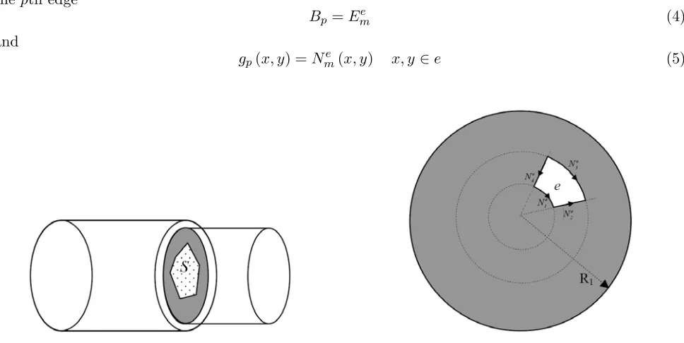
We consider a complex 2D discontinuity between two circular waveguides as shown in Fig. 1 whereS represents the aperture of the discontinuity. In the case of simple discontinuities between waveguides, the MVM provides a full-wave characterization of the complete structure [3]. Its principle is to minimize the following variational and stationary function [3]:
f(Et) =
EtY Eˆ t (1)
.|.denotes the inner product and ˆY the self-adjoint admittance matrix operator of the discontinuity [3]. When considering simple S aperture (i.e., rectangle, circle, ellipse, etc.) the tangential electrical field Et within the discontinuity can be expanded over the modal eigenfunction basis that satisfies the boundary conditions. When considering a complex S aperture as in Fig. 1, the determination of the modal eigenfunction basis is no longer analytical. To overcome this limitation, we express the tangential electrical field Et as in the FEM edge formulation [5]. The complex S aperture is divided into rectangular elements (in cylindrical coordinate system). Fig. 2 shows the shape of one element (e). In local numbering, the tangential electric field within the rectangular element (e) can be expressed as follows [5]:
Ee
t (x, y) =
4
m=1
Ee
mNme (x, y) x, y∈e (2)
Ne
m are the interpolation functions, andEem denote the tangential electric fields along the mth edge. We selected meshes conform to the coordinate lines of cylindrical coordinate system, which allows for separation of variables. However, for more complex apertures, triangle elements can be adopted. In global numbering, the tangential electric field within the apertureS can be expressed as:
Et(x, y) = M
p=1
Bpgp(x, y) (3)
M denotes the number of edges in the S aperture and Bp the unknown tangential electric field along thepth edge
Bp =Eme (4)
and
gp(x, y) =Nme (x, y) x, y∈e (5)
Figure 1. Complex discontinuity between circular waveguides.
In this paper, we choose first order interpolation functions. By combining (1) and (3), we obtain the following function:
f(Et) =
M
p=1
Bpgp(x, y)
Yˆ
M
q=1
Bqgq(x, y)
(6)
The scattering matrix of the circuit is obtained by minimizing the expression (6) with respect to Bp. The size of the basis functions depends only on the number of edges M in the discontinuity which is smaller than the number of modes used.
3. RESULTS
In our study, we analyse various forms of irises that have important practical interests in circular waveguide technology. Theoretically, the scattering matrix is of infinite dimension corresponding to the infinite number of modes. For numerical computations and after making a convergence study of the S-parameters, the number of modes is truncated to a finite size. To choose the number of modes used, we found in practice that the optimal way is firstly to arrange modes of the entire circuit by ascendant cut-off frequencies. Then, we take all modes having cut-off frequencies below a selected cut-off frequency F. The performances of the proposed hybrid method are compared to those obtained using HFSS. We found that both numerical CAD tools provided similar accuracies for all studied discontinuities which show the versatility of the proposed hybrid method. However, to converge, as presented in our earlier publications for complex rectangular waveguide discontinuities [9–11], we find that HFSS takes about 5 hours while our method takes a few minutes which represents an overall reduction in CPU time more than 99% in all studied structures.
3.1. Circular Iris
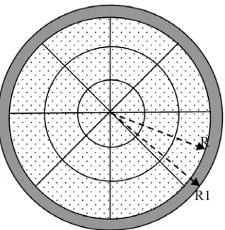
We consider a centred circular iris in a circular waveguide. Fig. 3 shows the geometries and meshing of the aperture. We selected a circular iris because the modal methods can obtain precise responses that can be used as references to compare the performances of the studied numerical methods. When applying a modal analysis [1–3], for dominant TE11 mode excitation, it is sufficient to consider only
TE1m and TM1m modes, wherem is an integer. However, when applying our hybrid method we have
to consider all modes.
Figure 3. Geometries and meshing of the circular aperture (24 elements). R = 12 mm, R1 =
13.4 mm.
Figure 4 displays the reflection coefficient of the circular iris using the suggested method and HFSS, respectively. For the classic MVM, we employed a sufficiently high number of modes (i.e., F = 150 GHz) to obtain a precise response of the circuit which can be used as reference. We observe that the proposed hybrid method, using 24 elements and F = 150 GHz, is successfully applied to the design of the discontinuity
3.2. Ridged Iris
The next example deals with the analysis of a circular ridged waveguide which is typically used in circular waveguide dual-mode CWDM filters to tune and couple each pair of degenerated modes [12]. To reduce the manual tuning, an efficient software tool for the full wave electromagnetic simulation of the complex discontinuity is required.
We consider multi-ridged irises in a circular waveguide. Figs. 5 and 7 show the geometries and the meshing of the studied apertures. Figs. 6 and 8 display the reflection coefficients for both cases using the suggested method and HFSS. We observe that both responses agree.
Figure 5. Geometries and meshing of the ridged aperture (11 elements), R= 10 mm.
Figure 6. Reflection coefficient of the ridged aperture (F = 150 GHz).
Figure 7. Geometries and meshing of the two ridged aperture (22 elements), R= 11 mm.
3.3. Multiaperture Iris
Multi-aperture resonant irises are commonly utilized for design of various kinds of filters such as bandpass and band rejection filters. They can be used as a tool to introduce additional attenuation poles to the bandpass filter response [13].
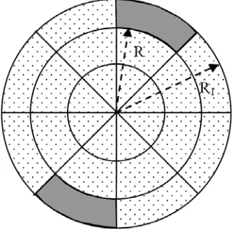
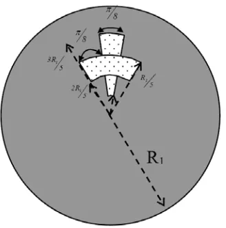
Figure 9 represents an example of a multi-aperture iris in circular waveguide which has arc-shaped opening. This kind of irises is widely studied in [13]. The performances of the proposed hybrid method are compared to those obtained using HFSS (see. Fig. 10). We observe that both results are comparable.
Figure 9. Geometries and meshing of the two aperture iris (2 elements), R = 10 mm, R = 12 mm.
Figure 10. Reflection coefficient of the two aperture iris (F = 150 GHz).
3.4. Cross Shaped Iris
The cross-shaped irises are generally used for the inter-resonator couplings in dual mode filters. Fig. 11 shows the geometries and meshing of the considered cross-shaped iris. Fig. 12 displays the reflection coefficients using the suggested method and HFSS. We observe that the two responses agree.
Figure 11. Geometries and meshing of the cross-shaped aperture (8 elements), R= 4 mm.
3.5. Off-Centred Iris
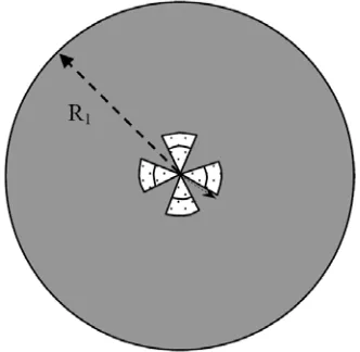
The off-centred irises offer more design flexibilities than concentric ones because they provide larger susceptance range [14, 15]. Our present effort is directed toward the analysis of complex off-centred irises in a circular waveguide. Fig. 13 shows geometries and the meshing of an off-centred cross-shaped iris. As observed in Fig. 14, the precisions of the proposed hybrid method are comparable to those obtained using HFSS.
Figure 13. Geometries and meshing of the off-centred cross-shaped aperture (3 elements).
Figure 14. Reflection coefficient of the off-centred cross-shaped aperture (F = 350 GHz).
4. CONCLUSION
We proposed a fast and accurate hybrid FEM-MVM tool to the complete CAD of 2D complex discontinuities in circular waveguides. The introduced hybrid FEM-MVM has been accurately applied to the analysis of several application examples of highly practical interest such as cross-shaped, multi-aperture, off-centered and ridged irises thus improving the computing time against FEM based CAD tools. Our hybrid method can be applied to the fast and accurate analysis of more structures containing complex discontinuities in circular waveguides.
REFERENCES
1. Wexler, A., “Solution of waveguide discontinuities by modal analysis,” IEEE Trans. Microwave Theory Tech., Vol. 15, No. 9, 508–517, Sep. 1967.
2. Shih, Y. C., T. Itoh, and L. Q. Bui, “Computer-aided design of millimeter-wave E-plane filters,” IEEE Trans. Microwave Theory Tech., Vol. 31, No. 9, 135–142, Feb. 1983.
3. Tao, J. W. and H. Baudrand, “Multimodal variational analysis of uniaxial waveguide discontinuities,”IEEE Trans. Microwave Theory Tech., Vol. 39, No. 3, 506–516, Mar. 1991.
4. Ferdinando, A., B. Giancarlo, and S. Roberto, “Admittance matrix formulation of waveguide discontinuity problems: computer-aided design of branch guide directional couplers,”IEEE Trans. Microwave Theory Tech., Vol. 36, No. 2, 394–403, Feb. 1988.
5. Jin, J., The Finite Element Method in Electromagnetics, 2nd edition, John Wiley & Sons, New York, 2001.
7. Arndt, F., et al., “Automated design of waveguide components using hybrid mode-matching/numerical EM building-blocks in optimization-oriented CAD frameworks — state-of-the-art and recent advances,” IEEE Trans. Microwave Theory Tech., Vol. 45, No. 5, 747–760, May 1997.
8. Arndt, F., et al., “Fast CAD and optimization of waveguide components and aperture antennas by hybrid MM/FE/MoM/FD methods-state-of-the-art and recent advances,”IEEE Trans. Microwave Theory Tech., Vol. 52, No. 1, 292–305, Jan. 2004.
9. Yahia, M., J. W. Tao, H. Benzina, and M. N. Abdelkrim, “Analysis of complex rectangular waveguide discontinuities using hybrid MVM-FEM,”Asia-Pacific Microwave Conference, 111–114, Dec. 2009.
10. Yahia, M., J. W. Tao, H. Benzina, and M. N. Abdelkrim, “Complex 2D discontinuities analysis using hybrid finite element method and a modified multimodal variational formulation-application to filter design,” European Microwave Conference, 1301–1304, Sep. 26–Oct. 1, 2010.
11. Yahia, M., J. W. Tao, and H. Sakli, “Complex rectangular filter design using hybrid finite element method and modified multimodal variational formulation,”Progress In Electromagnetics Research C, Vol. 44, 55–66, 2013.
12. Hu, H. and K. L. Wu, “A deterministic EM design technique for general waveguide dual-mode bandpass filters,”IEEE Trans. Microwave Theory Tech., Vol. 61, No. 2, 800–807, Feb. 2013. 13. Don, N. G., A. A. Kyrylenko, and L. P. Mospan, “A multi-aperture iris in a circular waveguide as
a tool for the frequency response control,” European Microwave Conference, 995–998, Sep. 2006. 14. Orfanidis, A. P., G. A. Kyriacou, T. Samaras, and J. N. Sahalos, “Mode matching analysis of
multiple offset coaxial irises in circular waveguide,” Electronics Letters, Vol. 40, No. 2, Jan. 2004. 15. Wu, A. K. L. and R. H. MacPhie, “A rigorous analysis of a cross waveguide to large circular