FPGA - BASED ARDUINO ARCHITECTURE
IMPLEMENTATION
IZA NURIZA BINTI AZIZ
A report submitted in partial fulfillment of the requirements for the degree of Bachelor Degree in Electronic Engineering (Computer Engineering)
Faculty of Electronics & Computer Engineering UNIVERSITI TEKNIKAL MALAYSIA MELAKA
UNIVERSTI TEKNIKAL MALAYSIA MELAKA
FAKULTI KEJURUTERAAN ELEKTRONIK DAN KEJURUTERAAN KOMPUTER
BORANG PENGESAHAN STATUS LAPORAN
PROJEK SARJANA MUDA II
Tajuk Projek : FPGA IMPLEMENTATION– BASED ARDUINO ARCHITECTURE
Sesi Pengajian : 1 5 / 1 6
1
Saya IZA NURIZA BINTI AZIZ
mengaku membenarkan Laporan Projek Sarjana Muda ini disimpan di Perpustakaan dengan syarat-syarat kegunaan seperti berikut:
1. Laporan adalah hakmilik Universiti Teknikal Malaysia Melaka.
2. Perpustakaan dibenarkan membuat salinan untuk tujuan pengajian sahaja.
3. Perpustakaan dibenarkan membuat salinan laporan ini sebagai bahan pertukaran antara institusi pengajian tinggi.
4. Sila tandakan ( √ ) :
SULIT*
*(Mengandungi maklumat yang berdarjah keselamatan atau kepentingan Malaysia seperti yang termaktub di dalam AKTA RAHSIA RASMI 1972)
TERHAD** **(Mengandungi maklumat terhad yang telah ditentukan oleh organisasi/badan di mana penyelidikan dijalankan)
TIDAK TERHAD
Disahkan oleh:
_________________________ ___________________________________
(TANDATANGAN PENULIS) (COP DAN TANDATANGAN PENYELIA)
iii
“I hereby declare that the work in “FPGA – Based Arduino Architecture Implementation” is my own except for summaries and quotations which have been
duly acknowledging.”
Signature : ...
Author : IZA NURIZA BINTI AZIZ
iv
“I acknowledge that I have read this report and in my opinion, this report is sufficient in term of scope and quality for the award of Bachelor of Electronic Engineering
(Computer Engineering with Honors)”
Signature : ...
Supervisor’s Name : EN. SANI IRWAN BIN SALIM
v
To my beloved father and mother: Your prayers keep me moving forward
Teachers
Fill my heart with the truth and knowledge Beloved friends
Make my world happens Every Muslim
vi
ACKNOWLEDGEMENT
I am grateful to God for the mercy and blessing were given to me to fulfill my Final Year Project, “FPGA – Based Arduino Architecture Implementation.”
In preparing this project, I would like to express my gratitude to my advisor Mr. Sani Irwan Bin Md Salim, for his constant support, guidance and valuable advice for the completion of this work and my graduate studies.
My sincere appreciation also goes to my family especially my parents who have morally and financially supported me from the beginning of my studies. Warmest regards to them for their seamless caring encouragement and moral support that has made this journey possible.
Last but not the least, I would like to thank my family: parents, brothers, and sisters for supporting me spiritually throughout writing this thesis and my life in general.
Finally, I would like to thanks to all people that help to fulfill this final year project. Thank you very much.
vii
ABSTRACT
viii
ABSTRAK
ix
TABLE OF CONTENT
CHAPTER TITLE PAGE
PROJECT TITLE i
PROJECT STATUS FORM ii
STUDENT’S DECLARATION iii
SUPERVISOR’S DECLARATION iv
DEDICATION v
ACKNOWLEDGEMENT vi
ABSTRACT vii
ABSTRAK viii
TABLE OF CONTENTS ix
LIST OF TABLES xii
LIST OF FIGURES xiii
LIST OF ABREVIATION xiv
1 INTRODUCTION 1
1.1 Overview 1
1.2 Problem Statement 2
1.3 Objectives 2
1.4 Scope of Project 2
x
2 LITERATURE REVIEW 4
2.1 Introduction 4
2.1.1 Introduction to FPGA 4
2.1.2 Introduction to Arduino 5
2.1.3 FPGA Architecture 5
2.1.4 Arduino Architecture 6 2.1.5 Differences between FPGA and
Microcontroller
7
2.2 Related Project 7
2.2.1 Cloud Based Development Framework Using IOPT Petri Nets For Embedded Systems Teaching [1]
8
2.2.2 A Low Cost Open Source High Frame- Rate-High Frequency Imaging System[2]
8
2.2.3 Implementation Of WSN Which Can Simultaneously Monitor Temperature Conditions And Control Robot For Positional Accuracy [3]
9
3 METHODOLOGY 11
3.1 Introduction 11
3.2 Flow Chart 12
3.3 Block Diagram 13
3.3.1 Papilio One 500k 14 3.3.2 Xilinx ISE Software 14 3.3.3 Arduino IDE Software 15
3.4 Software Application 16
xi
4 RESULTS AND DISCUSSION 20
4.1 Software 20
4.1.1 Coding 21
4.1.1.1 Signal section 21 4.1.1.2 Wishbone section 22
4.1.1.3 Peripheral Pin Select(PPS) section
23
4.1.2 Arduino IDE 25
4.2 Result 26
4.3 Discussion 27
5 CONCLUSION
5.1 Project conclusion 29
5.2 Recommendation 30
REFERENCES 31
APPENDIX 35
xii
LIST OF TABLES
TABLE TITLE PAGE
2.1 Comparison between the journals and this project 9
3.1 Comparison between VHDL and Verilog 19
4.1 Signal section 21
4.2 Wishbone section 22
4.3 Pps section 23
xiii
LIST OF FIGURES
FIGURE TITLE PAGE
1.1 FPGA Architecture 6
1.2 Arduino Architecture 6
3.1 Flow chart of the project 12
3.2 Block diagram of the system 13
3.3 Papilio One 500k Hardware 14
3.4 Xilinx ISE 14.7 interface 15
3.5 Arduino IDE interface 16
3.6 Xilinx ISE 14.7 Software 17
3.7 Arduino IDE Software 17
4.1 The output in Arduino IDE 26
xiv
LIST OF ABBREVIATION
FPGA - Field Programmable Gate Array
VHDL - Very High Speed Integrated Circuit Hardware Description Language
IDE - Integrated Development Environment
PWM - Pulse Width Modulation
DSP - Digital Signal Processor
ASIC - Application-Specific Integrated Circuit GPIO - General- purpose input/output
1
CHAPTER 1
INTRODUCTION
This chapter is about the implementation Arduino core processor on FPGA. This thesis will discuss the introduction, problem statement, objectives, and scope of the project. The end of this chapter will list the thesis outline.
1.1 Project Overview
In the world of electronics and digital circuitry, the term microcontroller is very widely used. Almost every single device that is meant to connect and interact with a computer has an embedded microcontroller inside to facilitate the communication. The structure of a microcontroller is comparable to a simple computer placed on a single chip with all of the necessary components like memory and timers embedded inside. It is programmed to do some simple tasks for other hardware.
2
on the structure basic arranging confinements in the current of a microcontroller which is it has a restriction issue and should have been supplanted with new innovation which is FPGA.
1.2 Problem Statement
The current Arduino-based system is custom-made to its particular board model. For example, Arduino UNO is for beginner level while Arduino Mega is for advanced level. The system configurations are restricted within the board specification hence limiting future expansion capability on the system.
1.3 Objectives of Project
The objective of this project is to develop Arduino-based architecture on FPGA platform.
1.4 Scope of Project
The job scope of this project is to implement Arduino processor core on FPGA. The hardware architecture is described using VHDL language. Xilinx ISE is used as a software and Spartan 6 Papilio One 500k FPGA board is utilized as the hardware programming platform in this project.
1.5 Chapter Review
3
statement, scope as well as chapter review are available within chapter 1 of this exposition. Thus, readers are well informed on the confinement about this research.
Chapter 2 comprises of literature review based on Arduino processor on FPGA. The corresponding of literature review will refine and zoom deeper into the concept which is closely related to my project through figure and diagram.
Chapter 3 presented the methodology of the analyzing and classification process of Arduino processor on FPGA. Flow chart of the project will be presented in this chapter with the description as well.
In chapter 4, all results from the project are included. The results are majority focus on software using Xilinx ISE and Arduino IDE is shown. The file also will test at FPGA processor to verify the file is creating well. The result will be presented in coding in this chapter.
4
CHAPTER II
LITERATURE REVIEW
This chapter summarizes the literature review on theoretical concepts applied in this project. It contains the information that the project required in order to develop and complete the entire project.
2.1 Introduction
2.1.1 Introduction to FPGA
5
2.1.2 Introduction to Arduino
Arduino is an open-source prototyping platform based on easy-to-use hardware and software. Arduino boards are able to read inputs for example light on a sensor, a finger on a button, or a Twitter message and turn it into an output with activated a motor, turning on an LED, publishing something online. The main advantage of the Arduino is, directly load the programs into the device without the need of a hardware programmer to burn the program. This is done because of the presence of the 0.5KB of the boot loader, that allows the program to be dumped into the circuit. By sending a set of instructions to the microcontroller on the board, the board will run their program smoothly. The Arduino software that usually used is Arduino programming language (based on Wiring), and the Arduino Software (IDE), based on Processing.
2.1.3 FPGA Architecture
Field Programmable Gate Arrays (FPGAs) are pre-fabricated silicon devices that can be electrically programmed in the field to become almost any kind of digital circuit or system. The general FPGA architecture consists of three types of modules. They are I/O blocks or Pads, Switch Matrix/ Interconnection Wires and Configurable logic blocks (CLB). The basic FPGA architecture has two-dimensional arrays of logic blocks with a means for a user to arrange the interconnection between the logic blocks. The functions of an FPGA architecture module are discussed and the FPGA architecture in Figure 1.1 is shown as below:
CLB (Configurable Logic Block) includes digital logic, inputs, outputs. It implements the user logic.
Interconnects provide direction between the logic blocks to implement the user logic.
Depending on the logic, switch matrix provides switching between interconnects.
6
Figure 1.1 : FPGA Architecture
2.1.4 Arduino Architecture
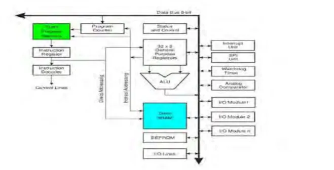
[image:20.595.192.522.521.689.2]Fundamentally, the processor of the Arduino board utilizes the Harvard engineering where the project code and program information have separate memory. It consists of two memories such as program memory and data memory. Wherein the data is stored in data memory and the code is stored in the flash program memory. Figure 1.2 below shows the architecture of Arduino.
7
2.1.5 Differences between FPGA and microcontroller
Almost every single device that is meant to connect and interact with a computer has an embedded microcontroller inside to facilitate the communication. The main and the most significant difference between the microcontroller and the FPGA is the structure of a microcontroller is comparable to a simple computer placed on a single chip with all of the necessary components like memory and timers embedded inside. It is programmed to do some simple tasks for other hardware. A Field Programmable Gate Array or FPGA is an integrated circuit that could contain millions of logic gates that can be electrically configured to perform a certain task.
FPGA does not have a fixed hardware structure, on the opposing, it is programmable according to user applications. However, processors have a fixed hardware structure. It means that all the transistors memory, peripheral structures, and the connections are constant. The very basic nature of FPGAs allows it to be more flexible than most microcontrollers. The term field programmable already tells that the whole FPGA device can be reprogrammed to do any logic task that can be fitted into the number of gates that it has. Microcontrollers already have their own circuitry and instruction set that the programmer must follow in order to write code for that microcontroller which restricts it to certain tasks.
Be that as it may, programming of FPGAs takes a more extended time to do a particular errand contrasted with the system a microcontroller. The developer needs to keep in touch with all the codes for the FPGA however for the microcontroller, the client can purchase programming bundles to program the microcontroller generally rapidly.
2.2 Related Project
8
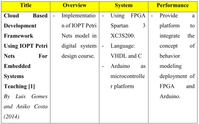
2.2.1 Cloud Based Development Framework Using IOPT Petri Nets For Embedded Systems Teaching [1]
This journal is prepared by Luis Gomes and Aniko Costa from University Nova de Lisboa, Faculty Science Technology & UNINOVA, CTS, Portugal in the year 2014.
This project is about the implementation of IOPT Petri Nets model in digital system design course. The IOPT-Tools [10] framework is used to support a cloud-enabled design automation flow, including specification of system’s behavior, state space based verification, and automatic code generation (C and VHDL) leading to implementation deployment into reconfigurable computing platforms ( FPGA based boards and Arduino devices). There are two parts of selected systems that were used in this project, which is for hardware implementation language, VHDL is selected and for a software implementation, C language is used. Besides that, this project was used FPGA Spartan 3 XC3S200 and Arduino as Microcontroller platform.
2.2.2 A Low Cost Open Source High Frame-Rate-High Frequency Imaging System[2]
This journal is prepared by J.A.Brown, M.Leung, A.Bezanson and R.Adamson from Biomedical Engineering, Dalhousie University, Halifax, NS, Canada in the year 2013.
9
2.2.3 Implementation Of WSN Which Can Simultaneously Monitor
Temperature Conditions And Control Robot For Positional Accuracy [3]
This journal is prepared by Sharul Agrawal from Department of Information Technology, Dharamsinh Desai University Nadiad, Gujarat, India and Ravi N. Prakash from Remote Handling & Robotics Development, Institute for plasma Research, Nr, Indira Bridge Gandhinagar, India in the year 2014.
[image:23.595.111.521.420.674.2]This project is about Implementation of wireless sensor networks in remote handling environment by sending signals over far distances by using a mesh topology transfers the data wirelessly and also consumes low power. The system that used in this project is FPGA NI Starter Kit with Atmega328(Arduino) and micro-controller + XBee. While for software part, Arduino IDE software that utilizes C language is used. This project is developing a prototype of Wireless Sensor Network(WSN) by deploying one temperature node to another node for temperature monitoring.
Table 2.1: Comparison between the journals and this project
Title Overview System Performance
Cloud Based Development Framework Using IOPT Petri
Nets For
Embedded Systems Teaching [1] By Luis Gomes
and Aniko Costa
(2014)
- Implementatio n of IOPT Petri Nets model in digital system design course.
- Using FPGA
Spartan 3
XC3S200. - Language:
VHDL and C
- Arduino as
microcontrolle r platform
- Provide a
platform to integrate the concept of behavior modeling deployment of
FPGA and
10
Title Overview System Performance
A Low Cost Open Source High Frame-Rate-High Frequency Imaging
System[2]
By J.A.Brown,
M.Leung,
A.Bezanson, and
R.Adamson (2013)
- Description of low cost open source
approach to
high-frequency ultrasound imaging system.
- Using FPGA
Virtex V. - Microcontrolle
r platform- Arduino Nano - Language:
Python language.
- The limitation preventing higher display frame rates is the serial calculations
used to
produced model images
from the
captured high-frequency data.
Implementation Of WSN Which Can
Simultaneously Monitor
Temperature Conditions And Control Robot For Positional Accuracy [3] By Sharul
Agrawal and Ravi
N. Prakash (2014
- The
advantage of wireless sensor
networks in remote
handling environment by sending signals over far distances by using a mesh topology transfers the data wirelessly
and also
consumes low power.
- Using FPGA NI Starter kit. - Microcontrolle
r platform: Arduino Atmega328 + XBee.
- Using Arduino IDE software that utilizes C language.
- Develop a
prototype of Wireless Sensor Network(WS
N) by
deploying one temperature
node to
another node for