Design and Analysis of Low Power
Temperature Sensor using Static Latch D
Flip-Flop
Gangotri Pareek , Gajendra Sujediya
M. Tech. VLSI Research Scholar, Department of EC, RIET, Jaipur, India
Assistant Professor, Department of EC, RIET, Jaipur, India
ABSTRACT: Temperature is unique of the supreme significant important physical quantities and is almost common in our day-to-day life and which is autonomous of the amount of material that means temperature have the intensive property. This dissertation shows a CMOS temperature sensor which is designed using self-bias differential voltage controlled ring oscillator at 180 nm TSMC CMOS technology to achieve low jitter operation. In this paper focuses on simulation, design and performance analysis for temperature sensor and its different components. The VCRO has limit with maximum voltage controllability along with a wide tuning range from 185 MHz to 810 MHz, and 93 MHz (free running frequency). The Power dissipation of Voltage controlled ring oscillator with power supply 313.91µW at 1.8V.
I.INTRODUCTION
Through the scaling down of present VLSI technologies, and it makes difficult to digital circuits have been implemented with lower supply voltage and a clock rate that introduces more constraints to analog circuits for this design of minimum voltage, analog circuitry with low-power has become important that the supply voltage is limited because of powered by batteries, the life moment of the battery is of great significance for the devices, factors address the necessities of low-power system building blocks and decrement in supply voltage restricts the signal swing in circuits and brings difficulties for analog circuit design. In a low-voltage environment, the transistor characteristics degrade and some circuit techniques can no longer be used, therfore the low-voltage is unlike from the traditional circuit design system.
II.BASICS OF TEMPERATURE SENSOR
Smart sensors are Micro-Electromechanical System (MEMs) devices that have more embedded features than ordinary sensors. They are smaller in size, cost effective and consume less power, and are aimed to detect and report information in unusual and extreme situations.
The information received from smart sensor is shared with an end user. One of the main properties of a smart sensor is sharing information among neighbours with over lapping sensing areas. Smart sensors with signal conditioning and embedded function are more adopted in the market.
Types of smart sensor
There are different types of smart sensors used in many fields of the industry like, biomedical application, control systems, security systems etc. These Microsystems combine sensing, accuracy and signal processing in a microscopic scale. Examples of smart sensors include [X]
• Temperature sensors • Pressure sensors • Accelerometer sensors • Optical sensors
Temperature sensor
applications, it would be striking to use temperature sensors that produce a ready interpretable temperature reading in a digital format. Such “smart” temperature sensors combine a sensor and interface electronics on a single chip, and are preferably manufactured in a low-cost standard CMOS process.
Fig : Schematic of temperature sensor component
The reset circuit is used to ensure that the oscillator is in the correct state when re-enabled for the next sample. It also reduces short circuit power dissipation resulting from the floating output node of the transmission gate.
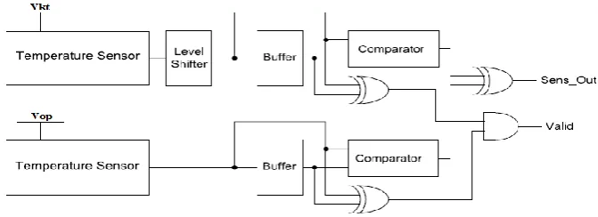
Complete circuit for temperature sensor shown below in fig . In this two temperature
Fig : Complete circuit of Temperature Sensor
sensors component are used which simultaneously take readings at the chosen VKT and the operating voltage of the system VOP (these temperature readings are referred to as TKT,t and TOP,t, respectively). Low-voltage level shifters are used to convert the lower voltage output to the higher voltage to perform comparison. Each reading is compared with its previous reading sample, TKT,t-1 and TOP,t-1, stored in buffers. The comparators circuits are used for comparison. The comparator outputs are then passed into an XOR gate, which determines if the temperature at VOP is the known or if it is the opposite.
Temperature Sensor component
Fig : Temperature Sensor component Temperature Sensor
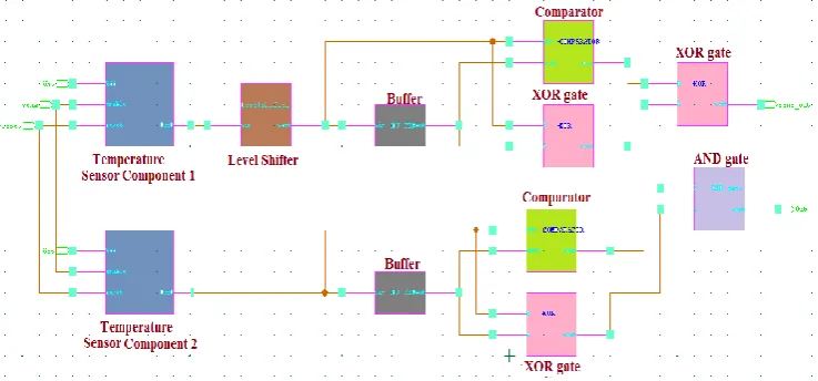
The complete diagram of temperature sensor contains two temperature sensor component, level shifter, 2 buffers, 2 comparator circuit, three XOR gate, one AND gate. Temperature sensor component is used to take readings simultaneously at given temperature readings VKT and operating voltage (VOP) of system.The readings (TKT,t and VOP,t) is taken at time t. Low-voltage up level shifter convert the lower voltage taken from output of temperature sensor component 1 to higher voltage. Comparator compares each temperature reading with previous temperature reading to produce output
Fig: Temperature Sensor
III.RESULT AND ANALYSIS
Simulation result and analysis of individual component used to design temperature sensor is discussed below. Temperature sensor is designed by means of 180nm TSMC technology.
Temperature Sensor Component
Fig 5.14: Waveform of Temperature sensor component
Delay and power dissipation of temperature sensor component is given in table 5.6.
Table 5.6: Delay & Power Dissipation at different VDD of Temperature sensor Component
At 1.8 V power
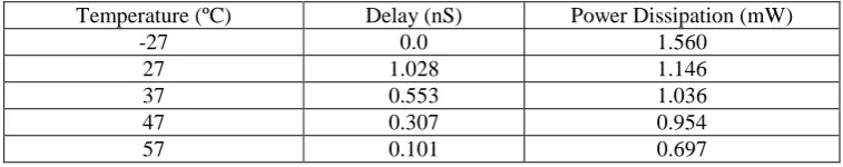
supply delay and power dissipation of temperature sensor component is also calculated at different temperature and different threshold voltage VTH, shown in table .
Fig : Power Dissipation and Delay versus VDD
Table : Delay & Power Dissipation of Temperature sensor Component at different Temperature
Temperature (ºC) Delay (nS) Power Dissipation (mW)
-27 0.0 1.560
27 1.028 1.146
37 0.553 1.036
47 0.307 0.954
57 0.101 0.697
Simulated waveform of temperature sensor component which is used for calculation of average power dissipation of circuit is shown in fig 5.16. Formula for average power dissipation is
Vdd(V) Delay (nS) Power Dissipation (mW)
1.8 1.528 2.1465
1.6 3.442 1.437
1.4 5.379 0.810
1.2 6.962 0.548
Average Power Dissipation =
2
min
max
P
P
Fig Waveform of power dissipation of Temperature sensor component
Temperature Sensor
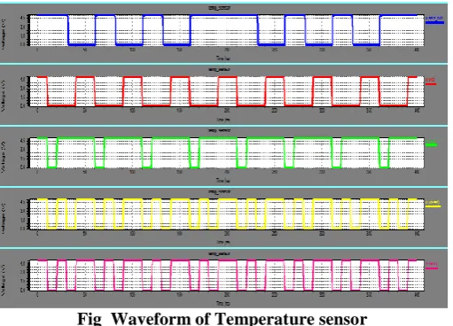
Simulated waveform of temperature sensor component is shown in fig5.17. Here input VKT is the temperature reading of temperature sensor component 1 whereVOP is the operating voltage of temperature sensor component 2 and sens_out is the output of temperature sensor. When temperature reading VKT sense by temperature sensor component 1 is different with operating voltage (VOP) of temperature sensor component 2, output is logic high otherwise logic low as shown in fig . Delay and power dissipation of temperature sensor component is calculated at by varying various parameters like power supply voltage temperature, threshold voltage and as shown in table .
Fig Waveform of Temperature sensor
Table : Delay and Power Dissipation of Temperature sensor at different VDD
VDD(V) Delay (nS) Power Dissipation (mW)
5 4.656 76.88
4 5.454 25.1
3 6.717 03.47
2 8.967 0.58
Table Delay and Power Dissipation of Temperature sensor at different Temperature
Temperature (ºC) Delay (nS) Power Dissipation (mW)
27 5.656 70.88
37 4.923 80.235
47 3.357 89.56
57 2.514 98.35
IV.CONCLUSION
A voltage controlled ring oscillator-based CMOS temperature sensor has been designed at 180 nm CMOS TSMC technology in Tanner Tool 13.1. smaller silicon area occupies by the proposed temperature sensor with higher resolution than the conventional temperature sensor based on band gap . The characteristic of VCRO is drawn between its control voltage and frequency. The frequency range of VCRO is calculated as 185 MHz to 810 MHz by its characteristic, with frequency of 93 MHz. Power dissipation of Voltage controlled ring oscillator at 1.8 V power is 313.91µW.
REFERENCES
[1] Ran Zhao, Gang Shao, Ni Li, Chengying Xu, and Linan An, “Development of a Wireless Temperature Sensor Using Polymer-Derived Ceramics”, Hindawi Publishing Corporation Journal of Sensors Volume 2016.
[2] S. A. P. de Jong, J. D. Slingerland, and N. C. van de Giesen, “Fiber optic distributed temperature sensing for the determination of air temperature”, Atmospheric Measurement Techniques, 15 January 2015
[3] Mr. Sambhaji Janardhan Nawale and Prof. Mrs. Joshi. Sareeka. G, “ Design and Implementation of Wireless Sensor Network”, IJARCSSE, Volume 4, Issue 12, December 2014 ISSN: 2277 128.
[4] Anthony Maher, Vijayalakshmi Velusamy, Daniel Riordan and Joseph Walsh, “Modelling of Temperature Coefficient of Resistance of a Thin Film RTD Towards Exhaust Gas Measurement Applications”, proceedings of the 8th international conference on sensing technology, 2014.
[5] Tarun Kumar Das, Yudhajit Das, “Design of A Room Temperature And Humidity Controller Using Fuzzy Logic”, AJER, Volume-02, Issue-11, p-ISSN: 2320-0936, pp-86-97.
[6] Abhishek Pandey , Divya Yadav , Ritika Singh and Vijay Nath, “Design of Ultra Low Power CMOS Temperature Sensor for Space Applications”, IJAREEIE, Vol. 2, Issue 8, ISSN: 2320 – 3765, August 2013
[7] Poonam and Prof. (Dr.) Yusuf Mulge, “Remote Temperature Monitoring Using LM35sensor and Intimate Android user via C2DM Service”, IJCSMC, Vol. 2, Issue 6 ISSN 2320–088X, June 2013, pg.32 – 36.
[8] Shruti Suman, Prof. B.P. Singh, “Ring Oscillator Based Cmos Temperature Sensor Design”, International Journal of Scientific & Technology, ISSN 2277-8616, Volume 1, Issue 4, May 2012.
[9] Stuart N. Wooters, Adam C. Cabe, Zhenyu Qi, Jiajing Wang, Randy W. Mann, “Tracking On-Chip Age Using Distributed, Embedded Sensors”, IEEE Transactions on Very Large Scale Integration (VLSI) Systems, Vol. 20, No. 11, November 2012.