ABSTRACT
POISEL, MATTHEW JOHN. Development of Draft Provisions for a Concrete Formwork Design Specification. (Under the direction of Dr. David W. Johnston.)
Formwork must be capable of handling all forces imposed on it due to the weight and
pressure of the concrete as well as any other loads imposed by personnel, materials,
equipment, or environmental loads. Currently there are no mandatory language standards for
the design of concrete formwork which may be referenced as required provisions. There is a
need for a formwork design standard in mandatory language that can be referenced by safety
regulations and project specifications to ensure the safe design of formwork for construction
of concrete structures. A review of existing standards and guides was performed to determine
existing provisions related to formwork. This review identified wind loads and load
combinations as areas requiring clarification in their application to formwork. Additional
wind provisions specific to formwork structures were developed. Draft provisions to address
the conflicts in load combinations between standards were developed. Current
non-mandatory guide provisions for determining the concrete lateral pressure were reformatted to
permit their use in a design specification. A design method and corresponding provisions for
the bracing of formwork to mass anchors was developed for incorporation into the draft
formwork design standard. A draft framework was developed to aid in the continued
Development of Draft Provisions for a Concrete Formwork Design Specification
by
Matthew John Poisel
A thesis submitted to the Graduate Faculty of North Carolina State University
in partial fulfillment of the requirements for the Degree of
Master of Science
Civil Engineering
Raleigh, North Carolina
2011
APPROVED BY:
_______________________ Dr. Michael L. Leming
_______________________ Dr. Min Liu
DEDICATION
This thesis is dedicated to all of those who have pushed me to continue to grow as a
student and a person. To all of my teachers and professors who have guided me through my
education. To all of my coworkers and supervisors who have provided me with experience
and training. And most importantly, to my Mother and Father, who have supported me
through this entire process and taught me the value of education and the importance of hard
BIOGRAPHY
Matthew J. Poisel was born in Raleigh, North Carolina in 1986. He grew up in Cary,
a suburb of Raleigh, and graduated from Cary High School in 2004. In august of 2004, he
enrolled in engineering at North Carolina State University, where he received Bachelor of
Science degrees in Civil Engineering and Construction Engineering and Management.
While earning his Bachelor degrees, he participated in the student chapter of the
American Society of Civil Engineers. He served as a team member on the ASCE Concrete
Canoe Competition his junior and senior years. During the fall of 2008, he completed and
passed the Fundamentals of Engineering exam. During his freshman and sophomore years,
he completed a Co-Op program with Northrop Grumman Newport News naval shipyard. In
the summer of 2008, he interned with United Forming Inc. at the UNC Physical Science
Building project in Chapel Hill, NC. In the spring and summer of 2009, he interned with
POLYCON Construction Group, LLC. in Raleigh, NC.
In August of 2009, he enrolled in the Construction Engineering and Management
graduate program in the Department of Civil, Construction, and Environmental Engineering
and North Carolina State University. Given the opportunity to expand his knowledge in
construction engineering, he became engaged in a research project with Dr. David W.
Johnston involving a design specification for concrete formwork. This research resulted in
ACKNOWLEDGEMENTS
I would like to acknowledge my family, especially my parents, Boyd and Charlene,
and my sister, Shannon. You have pushed me farther than I ever thought possible and have
supported me the entire way. Thank you for your help, your understanding, your love, and
when necessary, a push in the right direction. I love you all very much.
To my committee, Dr. David Johnston, Dr. Michael Leming, and Dr. Min Liu, thank
you for the time and effort you have devoted to making this thesis possible. I would like to
especially thank Dr. Johnston for guiding me through this process and his patience and
assistance with my copious questions.
I would also like to thank the faculty of the Department of Civil, Construction, and
Environmental Engineering at North Carolina State University. Many of you have supported
my efforts in both my undergraduate and graduate career. I can never repay the value of the
knowledge and experiences you have provided over the years, but I hope to carry it forward
TABLE OF CONTENTS
LIST OF TABLES ... vii
LIST OF FIGURES ... viii
1. INTRODUCTION ... 1
1.1. Background ... 1
1.2. Problem Statement ... 2
1.3. Research Objectives ... 3
2. REVIEW OF LITERATURE RELATING TO STANDARDS ... 4
2.1. Introduction ... 4
2.2. The United States Standards Strategy ... 4
2.3. The International Code Council ... 5
2.4. The American Concrete Institute ...6
3. REVIEW OF LITERATURE RELATING TO FORMWORK ... 7
3.1. Introduction ... 7
3.2. ACI 347 ... 7
3.3. ACI SP-4 ...10
3.4. ASCE 7 ... 11
3.5. ASCE 37 ... 15
3.6. OSHA Safety and Health Regulations for Construction ...21
3.7. Shapiro & Shapiro ...23
3.8. British Standard BS5975-2008 ...24
3.9. Other Source Documents ...24
4. DOCUMENT FRAMEWORK ... 25
4.1. Introduction ...25
4.2. Classification of Proposed Document ... 25
4.3. Language of Proposed Document ... 29
4.4 Format of Draft Provisions for Design Specification ...32
5. DRAFT PROVISIONS FOR CONCRETE LATERAL PRESSURE ... 34
5.1. Introduction ...34
5.2. ACI 347-04 Recommendations ... 34
6. WIND LOADS ON FORMWORK ... 39
6.1 Introduction ...39
6.2 ASCE 7 Wind Design Method ...39
6.3 Wind Speeds ...41
6.4 Reduction of Wind Speeds to Exclude Predictable Extreme Values ...44
6.5 Shielding of Wind ...46
6.7 Wind Loads for Generic Formwork Cases ...53
6.8 ACI 347-04 Minimum Recommendations ...55
6.9 Alternative Rational Analysis of Wind Loads ...59
7. LOAD COMBINATIONS AND LOAD FACTORS ... 60
7.1. Introduction ...60
7.2. LRFD and ASD Design Methods ...60
7.3. Application of ASCE 37-02 to Formwork ...61
7.4. Impacts of ASCE 7-10 on ASCE 37-02 Load Factors ...62
7.5. Impacts of OSHA Regulations on Formwork Design ...63
7.6. Incorporation of ASCE 347-04 Minimum Safety Factors into ASD and LRFD ...66
8. ANCHORAGE OF FORM BRACES ... 74
8.1. Introduction ...74
8.2. Mass Anchors on the Surface ...74
8.3. In-Ground Mass Anchors ...78
9. CONCLUSIONS AND RECOMMENDATIONS ... 81
9.1. Conclusions ... 81
9.2. Recommendations ... 82
10. REFERENCES ... 83
LIST OF TABLES
Table 5.1 Chemistry Coefficient Table from ACI 347-04 ... 37
Table 5.2 Draft Provision for Concrete Chemistry Coefficient ... 38
Table 7.1 LRFD and ASD Wind Load Factors ... 62
Table 7.2 Minimum Safety Factors for Formwork Accessories (from ACI 347-04) ... 67
LIST OF FIGURES
Figure 3.1 Commentary on Basic Wind Speed from ASCE 7-10 ... 14
Figure 3.2 Load types defined in ASCE 37-02 ... 16
Figure 3.3 Generalized Load Combination Equation from ASCE 37-02 ... 17
Figure 3.4 Load factors for specific load types listed in ASCE 37-02 ... 18
Figure 3.5 LRFD Basic Load Combinations (from ASCE 37-02) ... 19
Figure 3.6 ASD Basic Load Combinations (from ASCE 37-02) ... 19
Figure 4.1 Example Language and Format from ACI 318-08 ... 32
Figure 5.1 Concrete Lateral Pressure Recommendations from ACI 347-04 ... 35
Figure 5.2 Draft Provisions for Concrete Lateral Pressure ... 36
Figure 5.3 Cautionary Statement on External Vibration from ACI 347-04 ... 38
Figure 5.4 Draft Provision for Concrete Consolidated by External Vibration ... 38
Figure 6.1 Basic Wind Speed Reduction Factors from ASCE 37-02 ... 41
Figure 6.2 Draft Provisions for Determination of Wind Speed ... 43
Figure 6.3 Reduction of Wind Speed in Hurricane Regions from ASCE 37-02 ... 45
Figure 6.4 Draft Provisions for Shielding of Formwork by Obstruction ... 47
Figure 6.5 Draft Provisions for Shielding Coefficient for Repetitive Members ... 48
Figure 6.6 Detailed Analysis Methods from ASCE 7-05 ... 49
Figure 6.7 ASCE 7-05 Figure 6-20, Force Coefficients for Solid Freestanding Walls and Solid Signs ... 50
Figure 6.8 Draft Provisions for Force Coefficients for Elevated Slab Formwork (from BS 5975:2008) ... 52
Figure 6.9 Draft Provisions of Force Coefficients for Common Structural Shapes (from Shapiro & Shapiro) ... 53
Figure 6.10 Draft Provisions for Generic Wind Force for Wall Forms ... 54
Figure 6.11 Draft Provisions for Generic Wind Force for Elevated Slab Forms ... 54
Figure 6.12 Horizontal Loads Excerpt from ACI 347-04 ... 55
Figure 6.13 Derivation of Minimum Design Wind Load on Formwork ... 56
Figure 6.14 Deviation from Plum of Shores and Resulting Forces ... 58
Figure 6.15 Draft Provisions for Minimum Lateral Loads ... 58
Figure 6.16 Draft Provisions for Alternative Rational Analysis for Wind Force ... 59
Figure 7.1 Commentary to ASCE 37-02 related to Scaffolding Design ... 63
Figure 7.2 Draft Provisions of Scaffolding Requirements ... 64
Figure 7.3 Design Requirements for LRFD and ASD Design Methods (from AISC 360-05) ... 68
Figure 7.5 Calibration of LRFD Resistance Factors to ASD Safety Factors (from
AISC 360-05) ... 71 Figure 7.6 Typical Statics of Form Ties in Two-Sided Wall Forms ... 72 Figure 7.7 Calibration of LRFD Resistance Factor (Φ) to ASD Safety Factor (Ω)
for Form Ties ... 72 Figure 8.1 Statics of a Mass Anchor on the Ground Surface ... 75 Figure 8.2 Overturning and Sliding Provision from ASCE 37-02 ... 77 Figure 8.3 Calibration of LRFD Resistance Factors to ASD Safety Factors for
Mass Anchors ... 77 Figure 8.4 Free Body Diagram of a Cast-in-Ground Mass Anchor Subject to
1. INTRODUCTION
1.1 Background
Concrete is one of the most common construction materials in use in the world. One
of the major benefits of concrete is its ability to conform to any shape that can be imagined,
provided a form is designed to shape it. Formwork is used to support and control the shape of
fresh concrete. The complex shapes that can be produced using concrete result in complex
formwork. The formwork must be capable of handling all of the loads imposed on it through
the weight and pressure of the concrete as well as any other loads imposed by personnel,
materials, equipment, or environmental loads. It must also support the concrete structure until
the concrete has gained enough strength to support itself and all imposed loads.
The endless variations and complexities of formwork that may be required make it
difficult to develop a standard method of formwork construction. While the majority of
concrete forming may be considered routine; quite often there are shapes, structures, or
situations that are difficult to predict with a design standard. Even with the simplest of
structures, the available formwork materials and industry systems make it difficult to specify
a universal method for each case. Of primary importance when drafting any standard for
concrete is not only to ensure the safe construction of concrete structures, but also not to
limit, with stringent, prescriptive standards, the flexibility that concrete allows.
There are certain criteria that all formwork must meet to ensure the safety of
needed. To ensure that all formwork is built adequately and safely, the designer must be
aware of these design issues and the criteria for a functional and safe design.
1.2 Problem Statement
Currently there are no mandatory language standards for the design of concrete
formwork which formwork designers may reference as required provisions. Several guides
exist for formwork, but their language prevents their use as a mandatory standard. There is a
need for a formwork design standard in mandatory language that can be referenced by safety
regulations and project specifications to ensure the safe construction of concrete structures.
The failure of concrete formwork is a significant cause of injury on construction sites.
Particularly with multi-story concrete construction, the failure of formwork can be
catastrophic. Several major incidents, such as the collapse at Bailey‟s Crossroads in Virginia
in 1972 [1] and a cooling tower collapse at Willow Island, West Virginia in 1978 [2], have
shown that failure of concrete formwork can lead to progressive collapse situations, which
leave workers with little opportunity to escape from danger. Several existing standards and
guides try to address the problems that have occurred with concrete formwork in the past, but
there is no comprehensive, mandatory standard in the United States. A design specification
that addresses the specific issues of formwork is needed to clarify problems faced by
1.3 Research Objectives
The following research objectives have been identified:
1. Identify codes and design standards which contain provisions relevant to the design of
concrete formwork.
2. Identify guides for formwork that contain best practices in formwork construction.
3. Review current provisions and identify areas of formwork design not covered.
4. Develop a framework for a design specification on concrete formwork so that others
may input provisions relevant to formwork.
5. Develop a draft of selected provisions for concrete formwork as examples of possible
content.
6. Present a draft of the framework and provisions to ACI Committee 347 for review
and comment.
7. Make revised draft available to ACI Committee 347 for their continued development
2. REVIEW OF LITERATURE RELATING TO STANDARDS
2.1 Introduction
In order to develop a design standard for concrete formwork, the requirements for a
design standard must first be known. A review of literature relating to standards was
performed concurrently with the literature review of documents pertaining to formwork.
Several of the documents referenced have undergone changes during the process of this
study. An effort has been made to have the draft provisions recommended herein conform to
the most current information available.
2.2 The United States Standards Strategy
The United States Standards Strategy (USSS) [3] is a document published by the
American National Standards Institute (ANSI) to outline the principles and vision of
standards in the US and global economy. The USSS “consists of a set of strategic initiatives
having broad applicability that will be applied according to their relevance and importance to
particular sectors.” The second of the twelve initiatives of the USSS is to “continue to
address the environment, health, and safety in the development of voluntary consensus
standards”. This strategy set forth by ANSI is that standards be developed on a sector basis,
with individual sectors of the economy developing standards for their operations. “The
sectoral approach allows interested parties to address their own issues and develop working
“Sectors must develop their own plans; the purpose of this strategy is to provide guidance,
coherence and inspiration without constraining creativity or effectiveness.” [3]
2.3 The International Code Council
In the construction industry, standards can be broken down into many levels. Most
states or municipalities have adopted codes which serve as standards for constructed
facilities. These codes in turn reference standards that supplement the code with additional
provisions pertaining to specific aspects of construction. One organization that produces
model building codes is the International Codes Council (ICC). The reference standards
incorporated in the ICC model codes must meet the criteria of the ICC in order to be
incorporated into an ICC code. The ICC publishes the ICC Referenced Standards Guide [4]
to detail the requirements standards must meet to be considered for incorporation into a code
by reference. Building codes are legal requirements for permanent structures.
The temporary nature of formwork makes it inappropriate to incorporate a design
specification for formwork into a building code. Instead a design specification for formwork
could be incorporated by reference into a construction safety regulation or project
specification. While the proposed document is not intended to be referenced in a code, the
language of the document must meet the same requirements as a referenced standard in order
2.4 The American Concrete Institute
The primary industry organization focusing on cast-in-place concrete in the U.S. is
the American Concrete Institute (ACI). This organization currently publishes many of the
design standards relating to cast-in-place concrete, as well as guides to formwork design and
construction. ACI develops these documents through technical committees. The types of
documents produced and the process of developing documents by committees is established
in the ACI Technical Committee Manual [5].
The ACI Technical Committee Manual (TCM) has undergone several major revisions
recently, which will be discussed in detail in Chapter 4. The 2009 TCM [6] provided
requirements for non-mandatory language committee reports and for mandatory language
requirements for building codes and construction specifications. The 2010 ACI Technical
Committee Manual [5] includes changes to the ACI document classification system provided
for mandatory language design specifications. A draft of the 2011 ACI Technical Committee
Manual [7] is in the final stages of review and will soon be published. The 2011 draft of the
ACI Technical Committee Manual eliminates the references to the ACI Style Manual [8] and
the ACI Specifications Manual [9] and instead incorporates them into the TCM document as
chapters. An additional chapter has been drafted to provide format requirements for ACI
design standards. The evolution of the ACI document classification system is further
3. REVIEW OF LITERATURE RELATING TO FORMWORK
3.1 Introduction
The primary industry organization dealing with formwork for concrete is ACI. The
ACI guide documents ACI 347, “Guide to Concrete Formwork” [10] and ACI special
publication SP-4, “Formwork for Concrete” [11] provide recommendations to design and
construction personnel for formwork. These documents also reference other standards, such
as SEI/ASCE 7 “Minimum Design Loads for Buildings and Other Structures” [12] and
SEI/ASCE 37 “Design Loads on Structures During Construction” [13] which contain
provisions relevant to formwork design. In addition to the documents published by ACI, all
construction activities are subject to the requirements of the Occupational Safety and Health
Administration (OSHA) Safety and Health Regulations for Construction [14].
3.2 ACI 347
ACI 347 “Guide to Formwork for Concrete” is a guide document produced and
updated regularly by ACI Committee 347, with the latest published revision being ACI
347-04 [10]. It contains concise recommendations for the design and construction of formwork
systems. Several important areas covered in this document include: vertical loads placed on
formwork, concrete lateral pressures, lateral loads on formwork due to eccentricity of shores
and wind loading, and safety factors to be applied to components specific to formwork
ACI 347-04 provides many useful recommendations that a safety regulation or
project specification may wish to reference or require; however, this is not possible due to the
non-mandatory language of the document. On the first page of ACI 347-04, it states:
“Reference to this document shall not be made in contract documents. If items found in this
document are desired by the Architect/Engineer to be a part of the contract documents, they
shall be restated in mandatory language for incorporation by the Architect/Engineer.” This
document was never intended to be a mandatory language document, but instead a useful
guide.
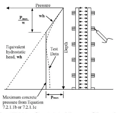
ACI Committee 347 has provided equations for estimating the concrete lateral
pressure on formwork since 1963 [15] and is referenced by many other publications as a
guide for formwork pressures. These pressure equations are revised as new information
becomes available. In ACI 347-04 the equivalent hydrostatic pressure of the fluid concrete is
the general case and additional equations are provided to estimate the concrete lateral
pressure when certain conditions apply. These conditions are related to the concrete mixtures
and concrete placement operations and the equations provide a reduced concrete lateral
pressure when the conditions are met. However, some difficulty has been noted in
interpreting the provisions in practice and improved presentation of the methods is needed.
These pressure equations are discussed in detail in Chapter 5 of this thesis. For estimating the
lateral pressure for concrete mixtures with newly introduced admixtures which affect the
slump or set characteristics, such as self-consolidating concrete, ACI 347-04 recommends
that specific mixture. ACI 347-04 also provides warning for certain concrete placement
operations and concrete mixtures where the concrete pressure may exceed the equivalent
hydrostatic head.
ACI 347-04 references several published mandatory standards which include
pertinent information related to formwork design, including SEI/ASCE 7 “Minimum Design
Loads for Buildings and Other Structures” and SEI/ASCE 37 “Design Loads on Structures
During Construction”, generally referred to as ASCE 7 and ASCE 37 respectively. No
specific version of ASCE 7 or ASCE 37 is referenced in ACI 347-04, but the most current
versions published at the time were ASCE 7-95 [12] and ASCE 37-02 [13].
ACI 347-04 recommends that wind loads be determined in accordance with ASCE 7
with adjustment for shorter recurrence intervals as provided in ASCE 37. ACI 347-04 also
provides minimum wind loads for wall forms and elevated slab forms. Minimum loads were
provided in the first publication of ACI 347 in 1963 [15] and were increased to the present
values in 1978 [16]. ACI 347-04 does not provide commentary on these recommendations
and the SP-4 section on wind loads does not provide information on how these minimum
loads were established.
ACI 347-04 provides minimum live load values for elevated slab formwork for
construction personnel and certain concrete placing equipment. A minimum live load value is
provided to cover the use of motorized carts to transport concrete to the area of placement.
Also provided are minimum design values for the combined dead and live loads on elevated
ACI 347-04 provides minimum safety factors for specific formwork accessories, such
as form ties, form anchors, and form hangers. The safety factors are stated as a ratio of the
ultimate strength of the accessory to the unfactored load combination that is applied to the
accessory. These minimum safety factors are directly applicable to Allowable Strength
Design (ASD) methods, which use unfactored loads in load combinations. However,
definition of these safety factors for Load and Resistance Factor Design (LRFD) methods is
not provided. Development of safety factors for ASD and LRFD is discussed in Chapter 7.
Although reference is made to ASCE 37 by ACI 347-04 for wind loads, ACI 347-04
does not reference ASCE 37 for load factors or load combinations to be used in designing
formwork. The only mention of load combinations in ACI 347-04 is in Section 2.2.1,
Vertical Loads, and Section 2.2.3, Horizontal Loads. Section 2.2.1 states: “Vertical loads
consist of dead and live loads.” Section 2.2.3 states: “Braces and shores should be designed
to resist all horizontal loads such as wind, cable tensions, inclined supports, dumping of
concrete, and starting and stopping of equipment.” Except as implied for ASD, these two
statements do not provide a clear picture of how a formwork designer should combine loads
imposed on formwork.
3.3 ACI SP-4
ACI SP-4 “Formwork for Concrete” is a manual authored by M. K. Hurd under
guidance of ACI Committee 347 and is considered by many to be the “Green Bible” for the
resent evolution of this manual first published in 1963 [17]. ACI SP-4 provides in-depth
coverage of the essential aspects of formwork system and design.
ACI SP-4 references ACI 347 when providing equations for concrete lateral
pressures. ACI SP-4 explains how each factor affects the concrete lateral pressure and
provides a brief history of the development of the equations. The concrete lateral pressure
equations in the 2005 edition of ACI SP-4 are based on the recommendations of ACI 347-04.
ACI SP-4 is updated as updates to ACI 347 are made; however it lags behind the revision of
ACI 347 by a few years.
Designers who have followed ACI SP-4s recommendations have had success in
designing safe, reliable formwork systems. However, since it is a non-mandatory language
document, its recommendations may not be referenced in safety regulations or contract
specifications as an enforceable requirement.
3.4 ASCE 7
ASCE 7 “Minimum Design Loads for Buildings and Other Structures” is primarily
referenced by building codes for loads on the final, permanent structure. For the design of
permanent structures, ASCE 7 provides basic load combinations which reflect the typical
loading conditions of a permanent structure. These basic load combinations are provided for
both LRFD and ASD design methods. The basic load combinations have changed through
the past three editions of ASCE 7, ASCE 7-95 [12], ASCE 7-05 [18], and ASCE 7-10 [19].
wind forces, as well as increase the live load factor in certain combinations. ASCE 7-10
made changes to ASCE 7-05 load combinations by decreasing the load factor for wind loads
in the basic combinations while increasing the wind load itself. A detailed discussion of the
changes in wind load factors is included in Chapter 7.
ASCE 7 contains information on wind velocities for regions in the United States,
which are used to determine the wind loads on a structure. It also contains several methods
for determining the wind pressure on different structure shapes. Most of these methods relate
to general building shapes and not specific members; however, there a few methods that can
be applied to formwork systems.
The analysis method for wind in ASCE 7-10 has been changed significantly from
previous editions. In the 1995 edition of ASCE 7, the wind speed was based on the maximum
wind three-second gust speed at 33 feet above ground in Exposure C and associated with an
annual probability of 0.02 of being equaled or exceeded for a 50-year mean recurrence
interval [12]. This maximum wind speed was used to calculate a wind force on a structure,
and in turn this force was multiplied by a load factor of 1.3 in LRFD combinations and 1.0 in
ASD combinations. ASCE 7-05 uses the same analysis method and provides the same basic
wind speeds, but with slight differences in contour line locations and an increased the wind
load factor to 1.6 in LRFD combinations, while maintaining the 1.0 in ASD combinations.
ASCE 7-10 has changed the analysis method for wind loads. When using LRFD,
instead of multiplying the wind force by a load factor of 1.6, the load factor is now 1.0 in the
same load combinations. An excerpt from the commentary of ASCE 7-10, shown in Figure
3.1, provides the reasoning behind the change in methodology in ASCE 7-10. To provide an
equivalent factor of safety for wind,ASCE 7-10 removes the Importance Factor for wind and
instead accounts for the buildings importance by establishing different wind contour maps for
different Importance levels; each with a different return period. To accommodate the change
in the LRFD load factor for wind from 1.6 to 1.0, the return period of the wind speed has
been increased from 50 years to 700 years for Category II structures. This increase in the
return period results in higher basic wind speeds, 115 hour instead of 90
miles-per-hour, and thus greater wind forces. To still allow the use of ASD, ASCE 7-10 now includes a
load factor of 0.6 instead of 1.0 on wind loads in ASD load combinations.
Section 6.5.10 of ASCE 7-05 can be used to determine the velocity pressure due to
wind speed for structures other than buildings, with adjustment factors to account for several
variables. These adjustment factors to the velocity pressure account for wind directionality,
exposure categories, surface roughness, importance of the structure, topographical effects,
gust effects, and the height of the structure above ground level. This velocity pressure is then
used in the appropriate analysis methods to determine the design wind force on a specific
Figure 3.1 – Commentary on Basic Wind Speed from ASCE 7-10 [19]
ASCE 7-05 provides analysis methods for different types and shapes of permanent
structures to determine the wind force. While many of the analysis methods do not relate to
formwork, two methods can be applied to typical formwork structures. The wind force
analysis method described in ASCE 7-05 section 6.5.14, “Design Wind Loads on Solid
Freestanding Walls and Solid Signs” can be directly applied to most wall forms in concrete
construction. The equation and adjustment factors provided give a design force at a specific
ASCE 7-05 section 6.5.15, “Design Wind Loads on Other Structures”, provides an
equation for determining the wind force on shapes of structures by using a shape factor “Cf”.
This shape factor is provided in ASCE 7-05 for several types of common permanent
structures; such as solid square or round structures, lattice frameworks, open signs, and
trussed towers. These structure shapes are often used in formwork systems and the shape
factors provided in ASCE 7-05 can be applied to that component of the formwork system.
However, since ASCE 7-05 is based on wind speeds corresponding to very long return
periods, it does not apply well to temporary structures that have very short periods of
exposure.
3.5 ASCE 37
ASCE 37-02 “Design Loads on Structures During Construction” [13] is intended as
the primary document for design loads on temporary structures, such as falsework and
formwork. Figure 3.2 provides the definitions of the load types shown in ASCE 37-02. This
document is intended to be compatible with ASCE 7-95 load factors and load combinations,
Figure 3.2 – Load types defined in ASCE 37-02 [13]
Included in ASCE 37-02 are load combinations for both LRFD and ASD methods.
LRFD and ASD load combinations are provided for temporary structures in construction.
These factors can be utilized in the design of formwork systems to ensure adequate strength.
ASCE 37-02 provides a general formula for combining all applicable loads multiplied
by their respective load factors as shown in Figure 3.3. Figure 3.4 shows the load factors
listed in ASCE 37-02. It also provides basic load combinations for LRFD and ASD design
methods similar to ASCE 7-95, but including additional construction loads. These basic load
combinations are shown in Figure 3.5 for LRFD and in Figure 3.6 for ASD.
ASCE 37-02 provides a special load factor called an Arbitrary Point-in-Time (APT)
value. This APT value is used to reflect that while one transient load may be at its maximum
value, other transient loads are unlikely to be at their maximum at the same time.. LRFD load
factors and APT values used in both ASD and LRFD load combinations are provided for
many types of loads that are seen in construction. The concept of using APT load factors is
provided in the commentary of ASCE 37-02, Section C2.2.1:
“The concept of using maximum and APT loads and corresponding load factors is consistent with ASCE 7-95. Here, in addition to the dead load, which is assumed to be permanent, one or more of the variable loads occurring simultaneously assume APT values (i.e., those values measured at any instant of time). This is consistent with the way loads actually combine in situations in which strength limit states are approached.”
[13]
ASCE 37-02 restates in mandatory language the recommendations of ACI 347R-94
[20] relating to concrete lateral pressure. ASCE 37-02 provides equations for determining
concrete lateral pressures, which the commentary states “The lateral pressure formulas are
adopted from ACI (ACI 1994; Hurd 1995)”, with ACI 1994 referring to ACI 347R-94 [20]
and with Hurd 1995 being the 6th edition of ACI SP-4 [21]. Both ACI documents referenced
by ASCE-37-02 have been revised since the edition listed and the recommended equations
have changed. As a result, the ASCE 37-02 equations do not provide adjustment factors for
concrete chemistry and unit weight factors as found in ACI 347-04. The factors listed in ACI
347-04, but not accounted for in SEI/ASCE 37-02, provide a better estimate of concrete
lateral pressure and therefore a more accurate formwork design. By stating the concrete
contract specifications as a requirement for design. However, revisions to ASCE standards
are published less often than ACI standards and often do not reference the most current ACI
standards or include ACI‟s current recommendations, which is problematic.
ASCE 02 references ASCE 7-95 for wind analysis methods. However, ASCE
37-02 provides reduction factors that can be applied to the basic wind speeds of ASCE 7-95 to
account for the short exposure duration of temporary works. ASCE 37-02 further allows
designers to ignore the effects of hurricane winds on coastal regions, provided that the
temporary structure is either removed or additionally braced in the event a hurricane is
predicted to strike. It also provides for the consideration of shielding of wind load on
repetitive members, like those commonly used in the shoring of concrete formwork.
ASCE 37 is in the process of being revised. At this point, there have been no
indications of how the revised ASCE 37 will address the changes in the wind analysis
method in ASCE 7-10. The next publication of ASCE 37 will need to be reviewed before
incorporation by reference into the proposed design specification for formwork.
3.6 OSHA Safety and Health Regulations for Construction
The formwork designer must ensure that the design is in compliance with the
Occupational Safety and Health Administration (OSHA) Safety and Health Regulations for
Construction Subpart Q on Concrete and Masonry Construction Section 1926.703(a) [14].
This regulation states “Formwork shall be designed, fabricated, erected, supported, braced,
loads that may reasonably be anticipated to be applied to the formwork”. While Subpart Q
does not specify any of these loads, it does provide in Subpart Q Appendix A non-mandatory
references containing information helpful in complying with the requirements. Among these
listed references are ACI 347-78 [16] and ACI SP-4. A specific edition of ACI SP-4 is not
referenced in OSHA; however, the most current edition is ACI SP-4, 7th edition [11].
OSHA Safety and Health Regulations for Construction Subpart L “Scaffolds” also
includes requirements that relate to formwork. The distinction of a structure being classified
as either formwork or scaffolding determines what the design requirements are for the
system. The primary requirement that impacts formwork design is found in §1926.451(a)(1),
“Except as provided in paragraphs (a)(2), (a)(3), (a)(4), (a)(5) and (g) of this section, each
scaffold and scaffold component shall be capable of supporting, without failure, its own
weight and at least 4 times the maximum intended load applied or transmitted to it” [14]. The
OSHA definition of a scaffold is found in §1926.450(b): “Scaffold means any temporary
elevated platform (supported or suspended) and its supporting structure (including points of
anchorage), used for supporting employees or materials or both” [14]. Some work platforms
are attached to and supported directly by the formwork system. OSHA refers to these types
of work platforms as form scaffolds and provides the following definition in §1926.450(b):
“Form scaffold means a supported scaffold consisting of a platform supported by brackets
attached to formwork” [14]. These work platforms are considered scaffolding and the
different live load requirements pertaining to scaffolding must be considered in the design of
“Large area scaffold means a pole scaffold, tube and coupler scaffold, systems scaffold, or
fabricated frame scaffold erected over substantially the entire work area. For example: a
scaffold erected over the entire floor area of a room.”
The classification of an elevated surface as formwork or a scaffold has a large impact
on the design of the elevated surface. The load combinations which that elevated surface
must be designed for change significantly. A detailed discussion of the OSHA requirements
and their impact on concrete formwork is found in Chapter 7 of this thesis.
3.7 Shapiro & Shapiro
The first edition of “Cranes and Derricks” by Howard I. Shapiro (1980) [22] is
mentioned in the commentary section C6.2.2 of ASCE 37-02 as a source of guidance on
shielding effects of wind on open structures [13]. The fourth edition by Shapiro & Shapiro
[23], released in 2011, also provides guidance on wind shielding. A detailed method is
provided for determining the shielding of repetitive members based on the shape and spacing
of the members. It also provides additional shape factors for wind loads on structural
members which are not provided in ASCE 7-05. This analysis method and the additional
shape factors are repeated in the draft provisions for the proposed design specification and
3.8 British Standard BS5975-2008
In reviewing standards for formwork, several standards from other countries were
identified. One standard in particular that provides provisions related to formwork in the U.S.
was British standard BS5975-2008 CORR: 2009 “Code of practice for temporary works
procedures and the permissible stress design of falsework” [24]. This standard provides an
analysis method consistent with ASCE 7-05 with a shape factor that is applicable to the
typical arrangement for forming an elevated slab. The provisions of BS5975 provide a basis
for some draft provisions in the proposed formwork design specification and are discussed in
Chapter 6 of this thesis.
3.9 Other Source Documents
Several other source documents are referenced in this thesis for specific information
or as examples of design methods. The specific section used from each of these documents is
sufficiently small to not merit their discussion in this Chapter. The pertinent information
4. DOCUMENT FRAMEWORK
4.1 Introduction
The framework of this draft specification is intended to provide a starting point for
ACI Committee 347 to continue its efforts on developing a design specification for
formwork. The framework for the draft design specification depends on the classification of
the proposed document within ACI publications. Also, the format of the design specification
is required to comply with the requirements of ACI. These requirements are discussed in this
chapter.
4.2 Classification of Proposed Document
ACI Committee 347 requested approval from the ACI Technical Activities
Committee (TAC) on November 11, 2009 to begin work to develop a mandatory language
document for concrete formwork. ACI Committee 347 requested that the document be titled
as a “design specification” rather than “code requirements” as would be required by the ACI
classification systems that existed at that time. An excerpt from the request letter is included
below:
ACI 347 notes that the present ACI document type for design requirements is a “code requirements” document. The committee believes it would be desirable for TAC to consider an alternate name under the same style, in particular a “design specification.” ACI Committee 347 believes that design requirements for formwork would most likely be cited by regulations, construction specifications and agreements other than building codes. The term “design specification” is used for many other design standards outside of ACI and would
TAC approved the request to develop a formwork design standard in March 2010.
Also, in response to the request, TAC revised the policies which define the classification of
documents published by ACI. The 2009 ACI Technical Committee Manual [6] had separated
documents published by ACI into two broad categories; “mandatory language documents
requiring standardization” and “nonmandatory language documents not requiring
standardization”. Under the mandatory language category, documents could be classified into
many types, but the two that were most relevant to the proposed document were as follows.
Code Requirements
ACI codes provide minimum requirements for concrete or masonry structures to safeguard the public safety, health, and general welfare.
If the code is written in a manner that it could be adopted in a more general code or by a regulatory agency, the phrase “code requirements” should be used in the title.
Reference specifications
Reference specifications are written to be referenced as part of a contract between an owner and a builder and must be worded in explicit,
mandatory language subject to only one possible interpretation.
ACI reference specifications must conform to the requirements of the ACI Specification Manual.
[6]
The ACI Specification Manual [9] states “this ACI specification manual provides
requirements and recommendations for preparing ACI construction specifications. ACI
construction specifications shall be prepared as either ACI Reference Specifications or ACI
Guide Specifications”. ACI specifications are only intended to be documents that could be
construction project specifications. Thus, neither is an appropriate classification for a design
specification.
Under the 2009 ACI TCM system of classifying published documents, the proposed
formwork document would appear to best fit under the classification of “code requirements”
since it is a design document. However, the formwork design standard is not intended to be a
building code provision since it does not cover elements of design for permanent structures
or buildings. ACI codes are not in themselves a legal requirement for design or construction,
but may become so by being incorporated by reference in a local or state building code or by
inclusion in the contract specifications for a construction project.
Several other professional and industry organizations also produce mandatory
language design documents and classify them as design specifications. These design
specifications are developed by their respective organization and then made available to the
public for review and comment like ACI standards. They then can be incorporated by
reference in model building codes or project specifications. Examples of such documents are
the “Specification for Structural Steel Buildings” [26] published by the American Institute of
Steel Construction and the “National Design Specification for Wood Construction” [27]
published by the American Forest and Paper Association. Thus, there are examples of design
standards that are not titled as “code” documents. If this draft document were classified and
title as “code requirements” under the previous ACI document classification system, there
recommended that the document be titled a formwork design specification to avoid this
confusion.
In 2010, the ACI Technical Committee Manual was revised to incorporate the new
mandatory language document classification of “design specification” [5]. The draft of the
2011 ACI Technical Committee Manual [7] continues to include this new document
classification. While still separating ACI documents into mandatory language and
nonmandatory documents, the new system now divides mandatory language documents into
subdivisions of “design standards” and “construction standards”. The classifications of “code
requirements” as well as the new classification of “design specification” fall under the
“design standards” subdivision. The classification of “design specification” is provided in
sub-paragraph 4.1.1.4 of the Draft 2011 Technical Committee Manual.
4.1.1.4 Design Specifications
A design specification provides minimum requirements for concrete or masonry structures within its scope to safeguard the public safety, health, and general welfare. It is written to be referenced in legal documents by entities other than building officials. Design specifications follow the code requirements format.
[7]
With the intent of the proposed document being a mandatory reference for the safe
design of formwork, it now falls under the ACI classification of “design specification”. This
classification serves the purpose of aiding the formwork designer while maintaining the
mandatory language requirement so that it may be incorporated by reference into project
specifications or safety regulations. If incorporated into project specifications or into federal
or state safety regulations, the provisions of this design specification would then be
4.3 Language of Proposed Document
While the proposed design specification is not intended to be referenced by a building
code, the writing requirements of a referenced standard for a code still apply. For all
standards referenced in ICC model codes, the ICC publishes the ICC Referenced Standards
Guide [4]. This guide goes into detail on the language to be used in a standard.
The need for mandatory language in referenced standards should be obvious in this context because a standard is intended to be utilized for regulatory
purposes. As a result, the standard must be presented so that the application and intent is clear to all readers. The use of recommendations, advisory comments, and permissive, non-mandatory terms fails to provide sufficient specific direction to all users. A potential result is non-uniform interpretation or
misapplication of the provisions. In particular terms such as „may‟, „should‟ and „can‟ are particularly significant in disrupting consistency of use as they create undefined conditional statements and can confuse the application of regulations
[4]
The draft of the 2011 ACI Technical Committee Manual covers much of the same
information as the ICC Referenced Standards Guide. It details the word use for provisions of
standards. Regarding the language and verb use in provisions of standards, it states:
5.2 – Language
5.2.1 Verb usage
Codes use only mandatory verbs, such as “Shall be” or “is”. Permissive verbs, such as “may” are never used. The verb in provisions that directs or permits a future action is usually “shall be”. The verbs in provisions that define a concept are in present tense, usually “is” and “are”. The mandatory mature of code language should be described in Chapter 1”.
[4]
The language of provisions for standards is intended to be thorough, yet as concise as
The ICC Reverenced Standards Guide addresses the need of additional information on
provisions in the statement:
This is not intended to mean that informational or explanatory materials cannot be developed to aid the reader in the use of the referenced standard. However, such material must be limited to a location within the document that is clearly identified as not being a mandatory part of the standard.
[4]
To provide this additional information on provisions, ACI documents may include
commentary for certain provisions. The ACI requirements for commentary are specified in
the draft of the 2011 ACI Technical Committee Manual:
5.1.6 Commentary to the code
Commentary may provide:
(a) Basis for the code provision including pertinent references; (b) Cross-reference to related material in other standards or in other
code sections;
(c) References to address situations outside the stated limits of a provisions; and
(d) Discussion highlighting new code provisions.
Commentary should not: (a) Repeat code provision;
(b) Provide general design education; or (c) Provide design aids or examples.
Commentary must not:
(a) Provide exceptions to the code provision; (b) Contain additional code requirements; or (c) Use mandatory language.
[7]
The proposed design specification is intended to conform to the requirements of the
provisions and the commentary, ACI design standards use a two-column format. The left
column contains the mandatory provision, while the right column contains the commentary to
that provision. The mandatory provisions are numbered using the ACI style and use Arial
font. The commentary is numbered to match the provision it applies to except that its number
is proceeded by an R. The commentary is written in Times New Roman font. An example of
this format from ACI 318-08 “Building Code Requirements for Structural Concrete and
Commentary” [28] is shown in Figure 4.1.
The draft provisions provided in Chapter 5 through Chapter 8 are a compilation of
provisions found in multiple standards as well as best practices reworded into mandatory
language. The provisions do not represent the entirety of draft provisions for any section.
Rather, the provisions provided in these chapters outline information found from other
sources and the changes required for use in a design specification. For the current working
6.1 – Design of formwork
6.1.1 – Forms shall result in a final structure that conforms to shapes, lines, and
dimensions of the members as required by the design drawings and specifications.
6.1.2 – Forms shall be substantial and
sufficiently tight to prevent leakage of mortar.
6.1.3 – Forms shall be properly braced or tied together to maintain position and shape.
6.1.4 – Forms and their supports shall be
designed so as not to damage previously placed structure.
6.1.5 – Design of formwork shall include
consideration of the following factors:
(a) Rate and method of placing concrete;
(b) Construction loads, including vertical, horizontal, and impact loads;
(c) Special form requirements for construction of shells, folded plates, domes, architectural concrete, or similar types of elements.
6.1.6 – Forms for prestressed concrete members shall be designed and constructed to permit movement of the member without damage during application of prestressing force.
R6.1 – Design of formwork
Only minimum performance requirements for formwork, necessary to provide for public health and safety, are prescribed in Chapter 6. Formwork for concrete, including proper design construction and removal, demands sound judgment and planning to achieve adequate forms that are both economical and safe. Detailed information on formwork for concrete is given in: ―Guide to Formwork for Concrete,‖ reported by
Committee 346. (This provides recommendations for design, construction, and materials for formwork, forms for special structures, and formwork for special methods of construction. Directed primarily to contractors, the suggested criteria will aid in preparing project specifications for the contractors.)
Formwork for Concrete, reported by ACI Committee 347. (This is a how-to-do-it handbook for contractors, engineers, and architects following the guidelines established in ACI 347. Planning, building, and using formwork are discussed, including tables, diagrams, and formulas for form design loads.)
Figure 4.1 – Example Language and Format from ACI 318-08 [28]
4.4 Format of Draft Provisions for Design Specification
The draft provisions are formatted to meet the Draft 2011 ACI Technical Committee
Manual‟s [7] requirements of chapter 5 “Format and Language for Codes” and chapter 9
specification, while the right column contains commentary on the provision. Text in italics is
information included to provide background and to identify issues the ACI Committee 347
must address before completing the design standard. The draft provisions of the following
chapters are provided in the U.S. inch-pound units only. The final design specification will
be published in two versions, one with U.S. inch-pound units of measure and the other with
the International Standards metric units of measure. The draft document in Appendix A
contains both units of measure and will be separated upon final development approval of the
draft by ACI Committee 347. The following detailed provisions will be considered in this
thesis:
concrete lateral pressures
wind loads on formwork
load combinations and load factors
5. DRAFT PROVISIONS FOR CONCRETE LATERAL PRESSURE
5.1 Introduction
The best available information for estimating concrete pressure based on U.S.
materials is found ACI 347-04. The concrete lateral pressure equations are updated as new
information becomes available and is evaluated by ACI Committee 347. The ACI 347-04
equations for concrete lateral pressure include adjustments for different cement types,
admixtures, temperature, unit weights of concrete, rate of placement, height of placement,
and shape of structure being placed.
5.2 ACI 347-04 Recommendations
ACI 347-04 recommends that unless certain conditions are met, formwork should be
designed for the full hydrostatic pressure based on the unit weight of the concrete mixture. It
allows the formwork designer to use a lower concrete pressure value if certain conditions are
met. These conditions include limitations on slump, placement height, depth of internal
vibration, and the use of admixtures. The provisions containing the concrete lateral pressure
equations are found in sub-section 2.2.2 of ACI 347-04 are shown in Figure 5.1.
ACI 347-04 presents the recommendations for the lateral concrete pressures in
paragraph form. This requires careful reading by the user of the document to ensure that they
use the appropriate equation for each specific design case. There is a current movement in
ACI code requirements to change from a paragraph-based format for provisions to a tabular
as a part of this effort, as shown in Figure 5.2. One table replaces approximately two
paragraphs of complex wording. This is done in an effort to make the standard easier and
faster to read. The designer can match the conditions of the specific design case to the
requirements of the standard much faster with the tabular and equation-based format.
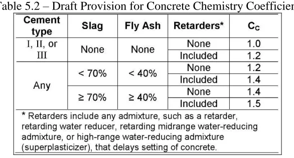
The table defining the Chemistry Coefficient in ACI 347-04 has been reformatted to
reduce the number of words needed to convey the information and also to clarify the
conditions. ACI 347-04 contains the conditions for each chemistry coefficient in sentence
form, as shown in Table 5.1. Two of the conditions for the chemistry coefficient state “Other
types or blends”, which can be incorrectly interpreted to exclude the already mentioned types
of Type I, Type II, and Type III. Also, the proportions of fly ash for each requirement are not
clearly worded. It is difficult to tell if the two conditions are for less than 40% fly ash or
exactly 40% fly ash. To clarify these conditions, the chemistry coefficient table was
reformatted and is shown in the draft Table 7.2.1.1c in Figure 5.4.
Table 5.2 – Draft Provision for Concrete Chemistry Coefficient
Recommendations of ACI 347-04 are written in non-mandatory language requiring
either rewording of the provision or placement in the commentary of the design specification.
An example of a recommendation requiring rewording can be found in Subsection 2.2.2.4 of
ACI 347-04 shown in Figure 5.3. The reworded draft of the provision can be seen in Figure
5.4.
Figure 5.3 – Cautionary Statement on External Vibration from ACI 347-04 [10]
6. WIND LOADS ON FORMWORK
6.1 Introduction
Wind loads on temporary structures pose a complex problem due to the varying
nature of wind and the interaction with different structures. ACI 347-04 recommends that
wall forms be designed for wind in accordance with ASCE 7 and using adjustment factors for
shorter durations from ASCE 37. ASCE 7 and ASCE 37 contain provisions for wind loads on
permanent and temporary structures respectively. Many factors must be considered in
determining the wind load on a temporary structure including wind speeds, surrounding
terrain, the shape of the structure, and effects of shielding. Many of the ASCE provisions
focus on the structure as a whole rather than individual components. Development of clear
guidelines for the application of these two documents to the design of formwork is needed.
6.2 ASCE 7 Wind Design Method
ASCE 7-95 and 7-05 use the same design method for wind loads, only with variations
of the input variables into the design equations. A design method usable for determining
wind load on formwork is outlined here.
First, the basic wind speed for the location is determined from a map of maximum
wind speeds. The wind speeds are based on an anticipated design life, and therefore exposure
period, of 50 years. This basic wind speed is used to determine the velocity pressure, qz, for
the object. The equation for velocity pressure is:
where:
qz = velocity pressure (lbs/ft2);
Kz = velocity pressure exposure coefficient; Kzt = topography factor;
Kd = wind directionality factor; V = wind velocity (mph); and I = importance factor.
The factors Kzt and Kd are used to account for topography effects of the surroundings and
directionality effects of the structure. The velocity pressure exposure coefficient, Kz, is a
factor that adjusts the wind pressure to account for the height of the object and the exposure
category. The importance factor, I, is used to reduce or amplify the wind pressure depending
on the risk to human life should the structure fail.
Second, the force, F, for a specific object shape is determined. For the shapes used in
formwork, the appropriate equation is:
F = qzGCfAf, (Eqn. 6.2)
where:
F = wind force on object; qz = velocity pressure; G = gust effect factor; Cf = force coefficient; and
Af = projected area normal to wind.
The gust effect factor, G, accounts for the dynamic response of the structure. For
formwork, the structure is assumed rigid and therefore G is 0.75 per ASCE 7-05. The force
coefficient, Cf, is used to adjust the velocity pressure to account for wind flow around the
ranges from 1.0 to 3.0. The resulting force, F, is typically applied at the center of area of the
structural shape; however, for some shapes, such as signs and freestanding walls, a different
location for this force is specified in ASCE 7-05 due to variation in pressure with height.
For temporary structures, the exposure period is considerably less than 50 years. To
account for this, ASCE 37 adjusts the basic wind speeds, as discussed in the following
section. Also, ASCE 7 does not permit the design for wind to consider shielding, the logic
being that the conditions that result in shielding cannot be predicted for a 50 year period.
However, ASCE 37 does permit shielding to be considered, but a design method for
shielding is not provided. A shielding design method is discussed later in this chapter.
6.3 Wind Speeds
ASCE 37-02 references ASCE 7-95 for basic wind speeds and provides factors for
reducing the ASCE 7-95 basic wind speed to a design wind speed for shorter exposure
durations typically seen in temporary works, such as formwork. These reduction factors to
the basic wind speed can be seen in Figure 6.1.
Since the pressure is a function of V2, the 0.75 factor, for example, reduces the
pressure to 0.752 or 0.56 of the normal pressure. ASCE 7-05 contains some improved
methods that can be applied to formwork that were not available in ASCE 7-95. There were
only minor changes in the wind speed maps from the 1995 to 2005 editions. Thus, it appears
the ASCE 7-05 can be used in combination with ASCE 37-02 without undermining the intent
of ASCE 37-02. However, the increased wind speeds of ASCE 7-10 are not compatible with
ASCE 37-02 and will be discussed in further detail in section 7.4 of this thesis. An explicit
statement could supersede the provision of ASCE 37-02 and allow the formwork designer to
use ASCE 7-05 provisions. To accomplish this, the draft design specification for formwork
requires in sub-section 7.3.1.1 that the basic wind speed and force calculation methods be
taken from ASCE 7-05. After determining the basic wind speed, sub-section 7.3.1.3 of the
draft states that reduction factors for shorter durations are applied per ASCE 37-02. These
6.4 Reduction of Wind Speeds to Exclude Predictable Extreme Values
In many coastal areas of the U.S., hurricane winds govern wind speeds for permanent
structures. However, hurricanes are random events whose occurrence is predictable on a time
scale relevant to temporary structures. Hurricanes are spotted and tracked weeks in advance
and warning of their impact on the U.S. is provided days in advance. This allows adequate
time to either provide additional bracing or to remove the temporary structure. In addition to
providing wind speed reduction factors, ASCE 37-02 allows designers of temporary
structures to exclude hurricane winds as shown in Figure 6.3. The basic wind speed is
reduced to 90 mile per hour in regions of the country subject to hurricane winds if the
structure is either removed or additional bracing is provided before onset of the hurricane. By
not requiring design to hurricane wind speeds, except when hurricane impact is imminent,
this reduces the maximum wind force that a temporary structure must be designed to resist,
increasing the economy of temporary structures.
It can be argued that even the 90 mile per hour basic wind speed that is the design
speed for the majority of the U.S. is also excessive for formwork. The Council for Masonry
Wall Bracing publishes a standard for designing the bracing of masonry walls titled
“Standard Practice for Bracing Masonry Walls Under Construction” [29]. This standard
addresses the issue of wind loads on work-in-progress and provides a rational for safe design
and construction. It does not require the masonry contractor to design the masonry structure
for the full wind speed of ASCE 7 or the applicable reduced wind speed of ASCE 37-02.
wind levels exceed working wind speeds. With modern weather prediction capabilities, often
warnings of high wind speeds are provided in advance of their occurrence, allowing for
additional bracing to be prepared for formwork systems. Furthermore, these wind speeds
occur during major storms in which a construction site would typically be evacuated and
unoccupied, posing very little risk of injury to personnel.
Figure 6.3 – Reduction of Wind Speed in Hurricane Regions from ASCE 37-02 [13]
Certain construction situations can pose risk to the public even when the site is
evacuated during storm conditions; examples being formwork construction in urban areas and
high-rise construction next to roadways. In these situations, it is reasonable to design the
formwork system to the full requirements of ASCE 37-02. While it would be economical for
formwork designers to be allowed to design to a lower wind speed in certain situations, there
interfering with other standards, it is recommended that this design specification should not
attempt to reduce the wind speed below those required in ASCE 37.
6.5 Shielding of Wind
Shielding is the situation where the wind pressure on an element is less because it is
protected by a windward object. ASCE 7-05 does not allow for consideration of shielding
when determining the wind force on a permanent structure because the windward object may
be removed in the long life of the structure. ASCE 37-02 does allow for the consideration of
shielding on temporary structures. The provisions for shielding do not provide a rigorous
methodology, but applies a reduction on repetitive members regardless of their shape or
spacing and allows a reduction when protected by surroundings.
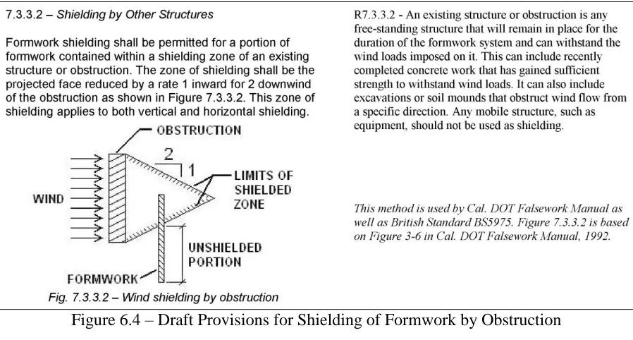
For temporary structures like formwork, the condition of the shielding structure by
surroundings can be predicted readily for the life of the system. The California Department of
Transportation Falsework Manual [30] provides a method of determining the shielding by an
obstruction. This method is proposed as the basis for provisions for shielding by other objects
Figure 6.4 – Draft Provisions for Shielding of Formwork by Obstruction
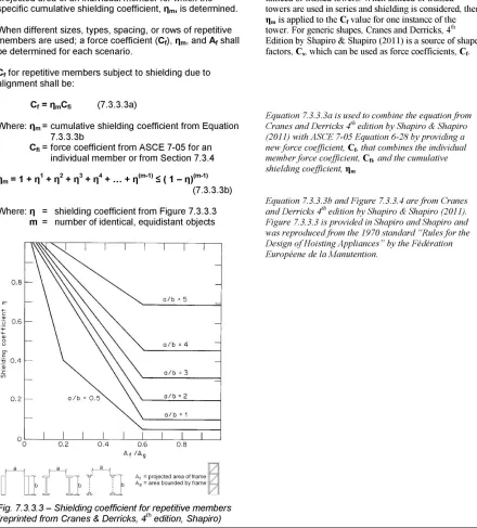
Shapiro and Shapiro provide a more detailed analysis method for determining the
shielding on repetitive members. The detailed analysis in Shapiro and Shapiro is used as the
basis for the draft provisions on shielding of repetitive members. This method requires the
calculation of a shielding coefficient, ηm, that that modifies the force coefficient for the
windward member. The shielding coefficient is a function of the shape of the member and the
spacing between members. The figure for determining this shielding coefficient provided in
Shapiro and Shapiro was reproduced from the 1970 standard “Rules for the Design of
Hoisting Appliances” by the Fédération Européene de la Manutention. The methodology
6.6 Detailed Analysis Methods for Wind Loads
ASCE 7-05 provides detailed methods of analysis for wind loads on certain shapes of
completed structures. One specific analysis method that is readily applicable to formwork is
ACSE 7-05 Section 6.5.14, Design Wind Loads on Solid Freestanding Walls and Solid Signs.
This analysis method provides force coefficients for various configurations of freestanding
walls similar to wall formwork. Figure 6.6 shows the provisions from ASCE 7-05 for
freestanding walls, using force coefficients from ASCE 7-05 Figure 6-20, which is shown in
Figure 6.7 of this thesis.
![Figure 3.1 – Commentary on Basic Wind Speed from ASCE 7-10 [19]](https://thumb-us.123doks.com/thumbv2/123dok_us/1346271.1167490/24.612.207.481.63.439/figure-commentary-basic-wind-speed-asce.webp)
![Figure 3.2 – Load types defined in ASCE 37-02 [13]](https://thumb-us.123doks.com/thumbv2/123dok_us/1346271.1167490/26.612.198.428.59.534/figure-load-types-defined-in-asce.webp)
![Figure 3.4 – Load factors for specific load types listed in ASCE 37-02 [13]](https://thumb-us.123doks.com/thumbv2/123dok_us/1346271.1167490/28.612.234.396.66.376/figure-load-factors-specific-load-types-listed-asce.webp)
![Table 5.1 - Chemistry Coefficient Table from ACI 347-04 [10]](https://thumb-us.123doks.com/thumbv2/123dok_us/1346271.1167490/47.612.168.467.343.472/table-chemistry-coefficient-table-aci.webp)
![Figure 6.3 – Reduction of Wind Speed in Hurricane Regions from ASCE 37-02 [13]](https://thumb-us.123doks.com/thumbv2/123dok_us/1346271.1167490/55.612.95.530.192.448/figure-reduction-wind-speed-hurricane-regions-asce.webp)
![Figure 6.6 – Detailed Analysis Methods from ASCE 7-05 [18]](https://thumb-us.123doks.com/thumbv2/123dok_us/1346271.1167490/59.612.181.453.298.577/figure-detailed-analysis-methods-asce.webp)