www.ijiset.com
107
PSO Based MPPT of PV System under Partial
Shading Condition
Saurabh Tripathi
P#
P
, Er.Roshan Nayak
P *P
, Er.Anupam Masih
P @P
#
P
Electrical Engineering, Sam Higginbottom University of Agriculture Technology and Sciences Allahabad, Uttar Pradesh India.
*Assistant Professor, Dept. of Electrical Engineering, SIET, SHUATS, Allahabad, Uttar Pradesh, India
P
@
P
Assistant Professor, Dept. of Electrical Engineering, SIET, SHUATS, Allahabad, Uttar Pradesh, India
27T
Abstract27T
—
This paper reports the improvement of a most extreme power-point following (MPPT) strategy for photovoltaic (PV) frameworks under in part shaded conditions utilizing firefly calculation. In the proposed system, the particle position is defined as the duty cycle valued
of the dc–dc converter, and the fitness value evaluation function is chosen as the generated power PRPVR of the whole PV system. In PSO initialization phase, particles can be placed on fixed position or be placed in the space randomly. In this work the particles are initialized on fixedpositions which cover the search space [
D
min,
D
max] with equaldistances. The goal of the proposed MPPT algorithm is to
maximize the generated power
P
PV. After the digital controlleroutput, the PWM command according to the position of particle i
(which represents the duty cycle command), the PV voltage
V
PVand current
I
PV can be measured and using voltage andcurrent sensor. These values can then be utilized to calculate the
fitness value
P
PV of particlei
. If the fitness value of particle i isbetter than the best fitness value in history
p
best,i , set currentvalue as the new ,i . Then, choose the particle with the best fitness
value of all the particles as the
g
best. After all the particles areevaluated, the velocity and position of each particle in the swarm should be updated with the help of eqn. 5.1 and 5.2. In this work two convergence criteria are utilized. If the velocities of all particles become smaller than a threshold, or if the maximum number of iterations is reached, the proposed MPPT algorithm will stop and output the obtained
g
best solution. Typically PSOmethod is used to solve problems that the optimal solution is time invariant. However, in this application, the fitness value (global maximum available power) often changes with environments as well as loading conditions. In such cases, the particles must be reinitialized to search for the new GMPP again. If following criteria is meet the particles are reinitialize.
,
|
|
(%)
PV new PVPV
P
P
P
P
−
≥ ∆
1. INTRODUCTION
With developing world vitality request and taking off costs of petroleum products together with worry about ecological issues have created colossal enthusiasm for the use of
www.ijiset.com
108
items. The yield intensity of the PV exhibit diminishes to a great extent because of PSC and the quantum of intensity lost rely upon framework arrangement, shading design and the detour diodes fused in the PV modules. The impact of PSC on PV framework has been examined in a few productions [16]– [18]. The prompt impact of PSC is that the subsequent PV trademark bend ends up complex with different pinnacles. Ordinary strategies for following MPP depend on "slope climbing" strategy and these techniques are not compelling in coming to the worldwide optima, when the PV framework under PSC shows different pinnacles; fairly the vast majority of the customary techniques may meet to neighborhood MPP prompting power misfortune. Removing most extreme power from in part shaded PV exhibits can be arranged into four gatherings [19]. In the primary gathering, changed MPP systems which are fit for joining to worldwide most extreme power point (GMPP) are utilized and the second class uses distinctive exhibit reconfigurations. The third gathering depicts diverse PV framework structures and the fourth class includes distinctive converter topologies, for example, staggered inverters. Despite the fact that not featured, a closer examination of the work in [19] obviously demonstrates that the last three classes are costlier, require more segments, and include complex control and higher exchanging misfortune in correlation with changed MPPT methods that fall under first classification. When all is said in done, altered MPP calculations dependably ensure combination to GMPP, framework freedom, and higher following effectiveness For the situation of a shaded PV framework, the PV bend has various pinnacles and union to worldwide MPP is compulsory for separating most extreme power from the PV framework. The enhancement calculation chose for MPPT ought to in a perfect world have the properties of basic computational advances, quicker combination, and ensured assembly to GMPP together with the practicality of execution in an ease computerized controller. Naturally motivated streamlining calculations, for example, hereditary calculations (GAs), subterranean insect province frameworks (ACS), fake safe frameworks (AIS), molecule swarm improvement (PSO) strategies, and so forth., have been widely utilized for different building applications. Among these techniques, PSO is basic in structure, computationally more affordable, and simple to fuse for online applications. Promoting the inalienable properties of PSO, a few researchers have recently employed PSO for GMPP tracking under partial shaded conditions [20]–[24]. These works employ conventional PSO and/or improved versions of PSO for enhanced tracking efficiency. It is shown that the proposed methods based on PSO guarantee convergence to GMPP and is far superior to conventional P&O method. While conventional PSO yields promising results [23], it causes oscillations in output power before reaching GMPP. An improved PSO where the duty cycles are initialized in two phases is reported in [22] which results in reduced steady state oscillations; however, the work in [22] does not compare the performance of the system with conventional PSO and its improved version. Furthermore, the two-stage initialization process may lead to increased computational burden and reduced tracking speed which are
not deliberated in [22]. It is important to mention that while most of the works [23], [24] claim that the PSO-based approach is superior to conventional methods of tracking, a comparison between PSO and conventional methods in terms of tracking speed through simulated and/or measured results is not available under identical conditions of partial shading; such a comparison of MPPT tracking could have highlighted the superiority of PSO. The PSO method for MPPT in PV systems under PSC is preferred by the researchers over other evolutionary algorithms because of its simple computation steps, easy of experimental implementation and increased tracking speed. The application of other evolutionary algorithms for MPPT under PSC is not available in the reported literature. Recently,Yang has developed ametaheuristic algorithm known as firefly algorithm (FA) and is available in [25], [26]. This algorithm is inspired by the flashing behavior of fireflies to attract other fireflies for mating purpose. It is shown in [26] that PSO is a special category of FA. The work in [26] compares PSO with FA by employing several multimodal optimization test functions. The statistical analysis of the comparison clearly indicates that FA is potentially more powerful in finding global optima with least computing time. A closer examination of the results presented in [26] highlights the superiority of FA over PSO in terms of convergence rate and computational burden. This aspect has been further verified in [27]. Recent works also confirmed the superiority of FA in solving complex optimization problems. The objective of this paper is to develop an FA-based scheme for tracking GMPP under PSC in a PV system. The proposed method is shown to be accurate, converges faster to GMPP and is system independent.
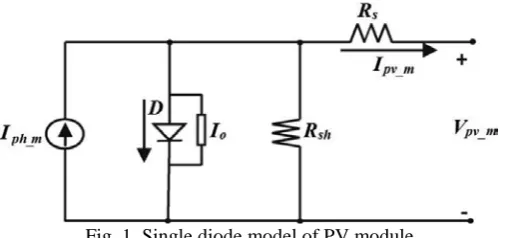
Fig. 1. Single diode model of PV module
www.ijiset.com
109
higher than 99.5%. The new MPPT scheme is simple, fast converging, does not require priory knowledge of the system. Further, the scheme is easily realized using a low-cost PIC16F876Amicrocontroller. One major highlight of this paper is that comparative evaluation of P&O, PSO, and FA methods have been experimentally carried out and presented, which is not available in the earlier publications.
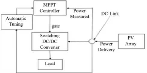
2 Perturbations and Observation (P&O) And/Hill-Climbing Technique
In this technique, first the PV voltage and current are measured and hence the corresponding power p1 is calculated. Considering a small perturbation of voltage (ΔV) or perturbation of duty cycle (Δd) of the dc/dc converter in one direction corresponding power P2 is calculated. P2 is then compared with P1. If P2 is more than P1, then the perturbation is in the correct direction; otherwise it should be reversed. In this way, the peak power point PRmppR is recognized and hence
the corresponding voltage can be calculated [18]–[20]. The major drawbacks of P&O/hill-climbing are occasional deviation from the maximum operating point in case of rapidly changing atmospheric conditions, such as broken clouds. Also, correct perturbation size is important in providing good performance in both dynamic and steady-state response [21].
Fig. 2. Block diagram of adaptive Hill-climbing technique.
To solve this problem, a modified adaptive hill climbing technique (Fig. 2) with a variable perturbation step size can be used [22], where an automatic tuning controller varies the perturbation step size to a large value when the power changes in a large range primarily due to environmental variation, to satisfy the fast response requirement during the transient stage. Further, the controller is formulated in such a manner that when the power change is less than or equal to the set lowest limit, the controller assumes that the system enters the steady state and the value of perturbation becomes small.In similar context, one Adaptive P&O technique [23] and another Predictive and Adaptive MPPT P&O technique [24] have been introduced. In the Adaptive P&O method, instead of, the main emphasis has been given on the voltage perturbation . In Predictive and Adaptive MPPT P&O method, a constant duty cycle perturbation that linearly reduces with increase of power drawn from PV panel has been taken.
3.PROPOSED SYSTEM
Step 1 (Parameter Selection): In the proposed system, the particle position is defined as the duty cycle value
d
of the dc–dc converter, and the fitness value evaluation function is chosen as the generated power PRPVR of the whole PV system.Step 2 (PSO Initialization): In PSO initialization phase, particles can be placed on fixed position or be placed in the space randomly. In this work the particles are initialized on
fixed positions which cover the search space [
D
min,
D
max]with equal distances.
Step 3 (Fitness Evaluation): The goal of the proposed MPPT algorithm is to maximize the generated power
P
PV. After thedigital controller output, the PWM command according to the position of particle i (which represents the duty cycle
command), the PV voltage
V
PV and currentI
PV can bemeasured and using voltage and current sensor. These values
can then be utilized to calculate the fitness value
P
PV ofparticle
i
.Step 4 (Update Individual and Global Best Data): If the fitness value of particle i is better than the best fitness value in
history
p
best,i , set current value as the new ,i . Then, choosethe particle with the best fitness value of all the particles as the
best
g
.Step 5 (Update Velocity and Position of Each Particle): After all the particles are evaluated, the velocity and position of each particle in the swarm should be updated with the help of eqn. 5.1 and 5.2.
Step 6 (Convergence Determination): In this work two convergence criteria are utilized. If the velocities of all particles become smaller than a threshold, or if the maximum number of iterations is reached, the proposed MPPT algorithm
will stop and output the obtained
g
best solution.Step 7 (Reinitialization): Typically PSO method is used to solve problems that the optimal solution is time invariant. However, in this application, the fitness value (global maximum available power) often changes with environments as well as loading conditions. In such cases, the particles must be reinitialized to search for the new GMPP again. If following criteria is meet the particles are reinitialize.
|
PV new, PV|
(%)
PV
P
P
P
P
−
≥ ∆
4. CRITICAL OBSERVATIONS UNDER PARTIALLY SHADED CONDITIONS
www.ijiset.com
110
unpredictable shading example of the vast PV cluster and, thus, to examine the qualities of the huge halfway shaded PV exhibit. A PV module [Fig. 1(a)] is thought to be shaded if at least three of its cells are accepting lower than typical insolation.
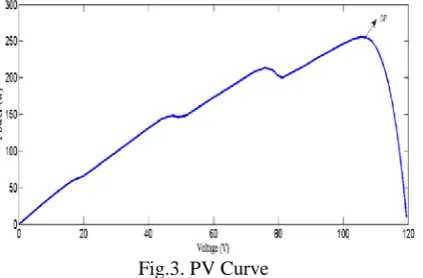
Fig.3. PV Curve
Arrangement associated PV modules, accepting comparable insolation, frame a "subassembly" [Fig. 1(b)]. A few arrangement associated subassemblies, each with an alternate level of insolation, shape a "arrangement get together" [Fig. 1(b)]. A "gathering" is comprised of a few comparative arrangement gatherings (having indistinguishable P– V attributes) associated in parallel [Fig. 1(c)]. Different parallel-associated gatherings, with various shading designs constitute a PV exhibit [Fig. 1(d)]. Fig. 2 demonstrates the P– V bends, got utilizing the created display, for a PV cluster having 900 modules (10 in arrangement × 90 in parallel) with a mind boggling shading design (having a few gatherings).
Fig. 3 shows the P–V curves for the array at different insolation levels. For further discussion, the simpler example of the shaded PV array shown in Fig. 1(d), having only three distinct groups, is considered. It is observed that the peaks
PS1, PS2, and PS3 occur at V1 = 65 V, V2 = 114 V, and V3 = 163 V, respectively. It is important to note that since four modules are unshaded in each series assembly of group 1, the peak PS1 occurs nearly at voltage V1 = 4× 16.3 = 65 V, where 16.3 V is 80% of the open-circuit voltage of the module (VOC_module) considered. A similar reasoning can be applied to PS2 and PS3, which occur at nearly V2 (= 7 × 16.3 = 114 V) and V3 (= 10 × 16.3 = 163 V), respectively. Hence, the peaks PAmax1, PAmax2, and PAmax3 occur nearly at the voltages V1, V2, and V3, respectively. A significant outcome of this observation is that the array power peaks are displaced from each other by an integral multiple of 80% of
VOC_module (n × 0.8 × VOC_module), where “n” is an integer. As the minimum integral difference in the number of shaded modules between the series assemblies of two groups is one, the minimum possible displacement between two consecutive peaks is 0.8 × VOC_module. In Figs. 1(d) and 2, the number of shaded modules in the series assemblies decreases as one moves from the first series assembly to the last one (i.e., from left to right).
5. DUTY CYCLE COMPUTATION FOR DC–DC CONVERTER CONTROL
Fig. 4(a) shows the circuit schematic of a boost-type dc–dc power converter whose duty cycle is modulated as per the algorithm used for electrical tracking of the MPP. In a conventional controller working with the P&O method, duty cycle (D∗) is generated as follows [22]:
D* = 1− (Vref/Vo) (1)
Fig. 4. (a) Circuit schematic for boost converter used for tracking MPP. (b) Proposed control scheme for the dc–dc converter. (LB = 5 mH, Cp = 2000 μH, Cf = 1000 μH, and Lf
= 0.1 mH).
where Vref is the reference voltage obtained using the MPPT algorithm described in Section 3, and Vo is the output voltage of the dc–dc converter. It is observed that such a controller is slow to respond. The proposed controller overcomes this drawback. Here, the control signal for dc–dc converter is obtained in a feedforward manner, as shown in Fig. 3(b). The controller is fast to respond and can quickly track the MPP. The principle involved in this controller can be mathematically explained as under. If ΔD is the perturbation in the actual duty cycle D, then
D+ΔD = 1− (Vpv +ΔVpv)/(Vo +ΔVo) (2)
where Vpv is the PV array voltage, while ΔVpv and ΔVo are changes in PV array and output voltages of the dc–dc converter, respectively.
If ΔVo _ Vo, then (2) leads to (3) as follows:
www.ijiset.com
111
Fig. 5 Proposed Circuit Diagram
Fig. 5. P–V characteristic for the array of Fig. 1(d), with solar insolation of 1000 W/m2.
This additional disturbance ΔD, when subtracted from the actual duty cycle D, amplifies the disturbance toward the MPP, and therefore, the MPP is attained quickly. The above mathematical analysis is explained with the help of Fig. 4, which shows the P–V curve of the array represented by Fig. 1(d). Point A indicates the initial operating point for which the PV array output voltage is Vin. To reach the MPP, the conventional controller sets the reference voltage Vref by giving a perturbation (here, reduction in the operating voltage) in such a way that the movement is toward the MPP. Vref is then used to calculate the new duty cycle D∗. As Vref < Vin,
the new duty cycle, D∗ = 1− (Vref/Vo), increases. As a result, the same output voltage Vo can be obtained by having a smaller PV array voltage. Thus, the operating point moves toward the MPP. In the proposed controller, an additional disturbance ΔD = k × (Vref − Vin) is introduced in the duty cycle computation, where “k” is a positive constant.
At Vref <Vin, ΔD is negative. The duty cycle for the next switching cycle is determined by two terms, namely
1) 1 − (Vref/Vo) and
2) ΔD, as given in the following:
D* = 1− Vref/Vo − ΔD. (4)
Similar to a conventional controller, the first term’s effect is an increase in the duty cycle for the next switching cycle. In addition, as ΔD is negative, the second term also increases the duty cycle. Hence, for the same output voltage Vo, the decrease in PV array voltage is much more than the previous case, which restores the MPP much faster than the conventional method.
6. SIMULATION RESULTS
This section presents the simulation results with the proposed algorithm. Fig. 6 shows the PV output current
Fig.6. PV Output Current
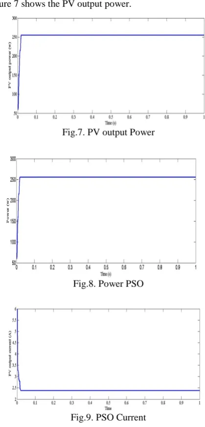
Figure 7 shows the PV output power.
Fig.7. PV output Power
Fig.8. Power PSO
www.ijiset.com
112
Fig.10. PV curve
Fig.11. Voltage PSO
7. CONCLUSIONS
The main aim of the present work is to develop an accurate MPPT algorithm for PV system under partial shading condition. The PSO based MPPT algorithm is implemented and a comparative study is done with the existing P&O MPPT algorithm From simulation results, it is found that the proposed PSO based MPPT algorithm is capable of tracking multiple global peaks under partial shading condition. To verify the reliability of proposed PSO based MPPT, the results comparison is drawn with P&O MPPT. It is found that under partial shading condition and varying solar radiation the tracking efficiency of PSO based MPPT shows better results than that of P&O MPPT.
REFERENCES
[1] J. H. R. Enslin, M. S. Wolf, D. B. Snyman, and W. Swiegers, “Integrated photovoltaic maximum power point tracking converter,” IEEE Trans. Ind.
Electron., vol. 44, no. 6, pp. 769–773, Dec. 1997. [2] T. Noguchi, S. Togashi, and R. Nakamoto,
“Short-current pulse-based maximum-power-point tracking method for multiple photovoltaic and converter module system,” IEEE Trans. Ind. Electron., vol. 49, no. 1, pp. 217–223, Feb. 2002.
[3] V. Salas, E. Olias, A. Barrado, and A. Lazaro, “Review of the maximum power point tracking algorithms for stand-alone photovoltaic systems,”
Sol. Energy Mater. Sol. Cells, vol. 90, no. 11, pp. 1555–1578, Jul. 2006.
[4] C. Hua, J. Lin, and C. Chen, “Implementation of a DSP-controlled photovoltaic system with peak power
tracking,” IEEE Trans. Ind. Electron., vol. 45, no. 1, pp. 99–107, Feb. 1998.
[5] N. Fernia, G. Petrone, G. Spagnuolo, andM. Vitelli, “Optimization of perturb and observe maximum power point tracking method,” IEEE Trans. Power Electron., vol. 20, no. 4, pp. 963–973, Jul. 2005. [6] T. Esram, J. W. Kimball, P. T. Krein, P. L. Chapman,
and P. Midya, “Dynamic maximum power point tracking of photovoltaic arrays using ripple correlation control,” IEEE Trans. Power Electron., vol. 21, no. 5, pp. 1282–1291, Sep. 2006.
[7] C. Dorofte, U. Borup, and F. Blaabjerg, “A combined two-method MPPT control scheme for grid-connected photovoltaic systems,” in Proc. Eur.Conf. Power Electron. Appl., Sep. 11–14, 2005, pp. 1–10. [8] K. H. Hussein and I. Muta, “Maximum photovoltaic
power tracking: An algorithm for rapidly changing atmospheric conditions,” Proc. Inst. Electr. Eng.— Generation, Transmission Distribution, vol. 142, no. 1, pp. 59–64, Jan. 1995.
[9] D. Sera, T. Kerekes, R. Teodorescu, and F.
Blaabjerg, “Improved MPPT method for rapidly changing environmental conditions,” in Proc. IEEE Int. Ind. Electron. Symp., Jul. 2006, vol. 2, pp. 1420– 1425.
[10] N. Kasa, T. Iida, and H. Iwamoto, “Maximum power point tracking with capacitor identifier for photovoltaic power system,” Proc. Inst. Electr. Eng.—Electr. Power Appl., vol. 147, no. 6, pp. 497– 502, Nov. 2000.
[11] N. Kasa, T. Iida, and L. Chen, “Flyback inverter
controlled by sensorless current MPPT for
photovoltaic power system,” IEEE Trans. Ind. Electron., vol. 52, no. 4, pp. 1145–1152, Aug. 2005.
[12] M. Veerachary, T. Senjyu, and K. Uezato,
“Maximum power point tracking control of IDB converter supplied PV system,” Proc. Inst. Electr. Eng.—Electr. Power Appl., vol. 148, no. 6, pp. 494– 502, Nov. 2001.
[13] R. Bruendlinger, B. Bletterie, M. Milde, and H. Oldenkamp, “Maximum power point tracking performance under partially shaded PV array conditions,” in Proc. 21st EUPVSEC, Dresden, Germany, Sept. 2006, pp. 2157–2160.
[14] W. Xiao, N. Ozog, and W. G. Dunford, “Topology study of photovoltaic interface for maximum power point tracking,” IEEE Trans. Ind. Electron., vol. 54, no. 3, pp. 1696–1704, Jun. 2007.
[15] G. Petrone, G. Spagnuolo, and M. Vitelli,
“Analytical model of mismatched photovoltaic fields by means of Lambert W-function,” Sol. Energy Mater. Sol. Cells, vol. 91, no. 18, pp. 1652–1657, Nov. 2007.
[16] E. Roman, R. Alonso, P. Ibanez, S.
www.ijiset.com
113
[17] M. Miyatake, T. Inada, I. Hiratsuka, H. Zhao, H. Otsuka, and M. Nakano, “Control characteristics of a Fibonacci-search-based maximum power point tracker when a photovoltaic array is partially shaded,” in Proc. IEEE IPEMC, 2004, vol. 2, pp. 816–821.
[18] K. Kobayashi, I. Takano, and Y. Sawada, “A study of a two stage maximum power point tracking control of a photovoltaic system under partially shaded insolation conditions,” Sol. Energy Mater. Sol. Cells, vol. 90, no. 18/19, pp. 2975–2988, Nov. 2006.
[19] E. V. Solodovnik, S. Liu, and R. A. Dougal, “Power controller design for maximum power tracking in solar installations,” IEEE Trans. Power Electron., vol. 19, no. 5, pp. 1295–1304, Sep. 2004.
[20] G. Walker, “Evaluating MPPT converter topologies using a MATLAB PV model,” J. Elect. Electron. Eng., Australia, IE Aust., vol. 21, no. 1, pp. 49–56, 2001.
[21] B. Bletterie and R. Bruendlinger, “Quantifying
dynamic MPPT performance under realistic
conditions—First test results: The way forward,” in
Proc. 21st Eur. Photovoltaic Solar Energy Conf. Exhib., Dresden, Germany, Sep. 2006, pp. 2347– 2351.
[22] H. Patel and V. Agarwal, “PV based distributed
generation with compensation feature under
unbalanced and non-linear load conditions for a 3-φ, 4 wire system,” in Proc. IEEE Int. Conf. Ind. Technol., Mumbai, India, Dec. 2006, pp. 322–327.
[23] Md. Sohrabi Nasrabadi , Yousef Sharafi,Md. Tayari, “A Parallel Grey Wolf Optimizer combined With opposition based learning”, IEEE Conf. swarm intelligence and evolutionary computation, pp.18- 23, 2016.
[24] Satyajit Mohanty, Bidyadhar Subudhi, Pravat Kumar Roy “A Grey Wolf-Assisted Perturb & Observe MPPT Algorithm for a PV System” IEEE Trans. On energy conversion, vol. 32 no. 1 march 2017.
[25] A. Woyte, J. Nijs, and R. Belmans, "Partial shadowing of photovoltaic arrays with different system configurations: literature review and field test results", Solar Energy, Vol. 74, Issue 3, pp. 217-233 March 2003.
[26] W. Xiao, N. Ozog, and W. G. Dunford, "Topology Study of Photovoltaic Interface for Maximum Power Point Tracking", IEEE Trans. on Industrial Electronics, Vol. 54, No. 3, pp. 1696-1704 June 2007.