Simulation and Analysis of PWM Controlled
Cycloconverter Fed Split Phase Induction
Motor
Shashank Mishra*1, Mirza Mohammad Shadab2, Isarar Ahmad 3
M.Tech Student (Instrumentation and Control ), Department of Electrical Engineering, Integral University,
Lucknow (U.P.), India1
Assistant Professor, Department of Electrical Engineering, Integral University, Lucknow (U.P.), India2
Assistant Professor, Department of Electrical Engineering, Integral University, Lucknow (U.P.), India3
ABSTRACT: The split phase induction motor are fixed speed motor used in most industrial processes due to their
reliability, rugged nature, low maintenance and reduced cost. Induction motor use is limited in many industrial applications requiring variables speed due to high costs incurred in methods of speed control and efficiency of the methods used. This paper is implemented to control the speed of split phase induction motor using PWM technique based cycloconverter. The cycloconverter is built on with IGBT due to its improved dynamic performance, efficiency and reduction in the level of audible noise. With the help of PWM minimizes the lower order harmonics i.e. 1 and 3 order. In this paper simulink model of PWM based triggered cycloconverter is developed and the results shows that the output response is 2 & 4 times to input response. The output response of the cycloconverter is applied to the split phase induction motor and various output response of motor have obtained then observed the main & auxiliary winding current and speed-torque characteristics of the split phase induction motor.
KEYWORDS: 1-phase Cycloconverter,Split phase Induction Motor,PWM pulse generator.
I. INTRODUCTION
cycloconverter is applied to the single split phase induction motor and various output response of motor are obtained. Therefore it’s analyzed the main & auxiliary winding current and speed-torque characteristics of split phase induction motor. The results also shows that torque & rotor speed are varied and also increases after regular time interval. Here PWM Generator is used to generates a triggering waveform for cycloconverter and also used to minimizes the lower order harmonics i.e. 1 and 3 order in output voltage[8].
II. SINGLE PHASE CYCLOCONVERTER
A device which converts input at one frequency to output power at a different frequency with one-stage conversion is called a cycloconverter. A cycloconverter are two types –
A. STEP UP CYCLOCONVERTER:- This types of cycloconverter increase the output frequency with respect to input
frequency.
B. STEP DOWN CYCLOCONVERTER:- This types of cycloconverter decrease the output frequency with respect to
input frequency.
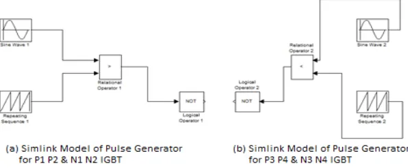
In this section basic principle of operation of step up as well as step down cycloconverter is presented. For understanding the principle of step down cycloconverter requires force commutation. It consists of eight thyristors P1 to P4 and N1 to N4, P for positive group and N for negative group as shown in fig. 1. During the positive half cycle of a supply voltage thyristors P1 & P2 and N1 & N2 are forward biased. The forward baisedthristors P1 & P2 are turned
on together at wt = 0 and N1 & N2 are turned on together at 3π for 2 times output response to input response and 4π for
4 times output response to input response. During negative half cycle thyristors pair P3 & P4 and N3 & N4 are forward
baised. The forward baisedthyristors P3 & P4 are turned on together at wt = π and N3 & N4 are turned on together at 4π for 2 times output response to input response and 5π for 4 times output response to input response as shown in fig. 3
& 4[6].
Fig. 1:Single phase bridge type of cycloconverter Fig. 2: Input voltage waveform of cycloconverter
The rms value of output voltage of cycloconverter is given by: Vor = [ ∫ Vm2 sin2ώtd(ώt)]1/2
α is s firing angle, Vm is a maximum voltage of input supply and here firing angle (α) is 0o[6].
C. SIMULINK MODEL OF CYCLOCONVERTER
This is a simulink model of single phase bridge type cycloconverter at resistive load. IGBT used in behalf of the thyristors as shown in fig. 5 , IGBT will work when external pulse applied to the IGBT. The IGBT P1 & P2 are triggered by pulse generator 1, IGBT P3 & P4 are triggered by pulse generator 2, IGBT N1 & N2 are triggered by pulse generator 3, IGBT N3 & N4 are triggered by pulse generator 4. The P groups IGBT is used for positive waveform and N groups IGBT is used for negative waveform. By this simulink model, cycloconverter are developed 2 & 4 times output response to input response at resistive load as shown in fig. 3 & 4 according to time duration of pulse generator.
Here all IGBT are fired at angle 0o it means IGBT acts like a diode [3].In this simulink model 50 hz & 230 V is used as
input signal, 8 IGBT and 4 different types pulse generator is used. In this paper these output waveform of cycloconverter are developed by two techniques i.e. simple pulse generator based and PWM generators. The cycloconverter are triggered by the pulse generator and PWM generator are developed same responses. This paper is analyzed that PWM controlled cycloconverter, output response of cycloconverter are applied to the split phase induction motor and various output response of motor have obtained. In this paper cycloconverter triggered by PWM generator and developed response are applied to the motor. After that response of motor i.e. main winding current, auxiliary winding current, rotor speed and torque characteristics have observed. Here simulink model of cycloconverter have simulated, designed and analyzed, after that modelling and simulated the single split phase induction motor in next portion [5].
Fig. 5: Simulink Model of Single Phase Cycloconverter When Cycloconverter triggered by External Pulse Generator
III. MODELLING OF SPLIT PHASE INDUCTION MOTOR
physical windings. The squirrel cage rotor is represented by equivalent two coils transformed to the stationary d-q axis as shown in fig 6.
Ψsα=Ls*isα+Lmα*irα
Ψsβ=Lsβ*isβ+Lmβ*irβ
Ψrα=Lmα*isα+Lrα*irα
Ψrβ=Lmβ*isβ+Lrβ*irβ
The voltage equation of the motor can be written in the d-q stationary frame as follows:
Isα= ((Lrα*ψsα-Lmα*ψrα) / (Lsα*Lrα- mα))
Isβ= ((Lrβ*ψsβ-Lmβ*ψsβ) / (Lsβ*Lrβ- mβ))
Fig.6: d-q Transformation of the split phase induction motor Fig.7: Torque speed characteristics of split phase induction motor
Isα= ((Lsα*ψrα-Lmα*ψrα) / (Lsα*Lrα- mα))
Isβ= ((Lsα*ψrα-Lmα*ψsα) / (Lsβ*Lrβ- mα))
The equations of motion are given by:
Te=p(Lmβ*isβ*irα - Lmα*isα*irβ )
J w = Te – T
where Vsα,Vsβ,Vrα,Vrβ are the stator and rotor voltages Isα,Isβ,Irα,Irβare the stator and rotor currents ψsα,ψsβ,ψrα,ψrβ are the
stator and rotor flux linkages Rsα,Rsβ,Rrα,Rrβ are the stator and rotor resistances Lsα,Lsβ,Lrα,Lrβ are the stator and rotor
inductances Lmα,Lmβare the magnetizing inductances, ώr is the electrical rotor angular speed, Te is the electromagnetic
torque, T is the load torque, J is the rotor moment of inertia, is the differential operator and α is the main per
A. SIMULINK MODEL OF SPLIT PHASE INDUCTION MOTOR
Fig. 8: Simulink model of split phase induction motor
This is a simulink model of split phase induction motor which developed in MATLAB 2011. In this model 230 V 50 hz AC voltage source is connected. Ramp & Saturation blocks is used for the motor saturation state and gain block is used to amplifies the rotor speed [7].
IV. PWM TECHNIQUES
In this type of modulation technique sine wave used as a reference signal and traingular signal used as a carrier signal. It can say that triangular signal travel with the reference of the sine wave. A high frequency triangular carrier wave is compared with a sinusoidal references wave of the desired frequency. The intersection of carrier wave and reference waves determines the switching instants and commutation of the modulated pulse. When sinusoidal wave magnitude higher than the triangular wave, the comparater output is high, otherwise it is low. When triangular carrier wave its peak coincident with zero of the reference sinusoid, there are N = pulses per half cycle. In case zero of the triangular wave coincides with zero of the
V. SIMULATION RESULTS
This is a simulation model of PWM based cycloconverter fed single split phase induction motor as shown in fig. 10.In this model single phase cycloconverter triggered by PWM generator, then the cycloconverter developed 2 & 4 times output response to input response of voltage and current then developed waveform are applied to split phase induction motor.Therefore it’s analyzed the main & auxiliary winding current and speed-torque characteristics of the split phase induction motor. Rotor speed and torque characteristics are varied and increases after regular interval of time. PWM based cycloconverter have also removes the lower order harmonics in output voltage waveform i.e. 1 and 3 order and its gives better response compare than the other techniques. The cycloconverter are triggered by two techniques i.e. pulse generator and PWM generator. The average output voltage waveform of cycloconverter is different from sinusoidal since the firing angle is held constant. The current waveform is not repeated after every cycle in main & auxiliary winding current and observed that some circulating current limit in reactor is connected between the positive and negative converter.The different frequency at cycloconverter is also useful flywheel from the operating machine which reduces the cause of torsional vibration and fatigue damage of the machine. The simulink model of PWM controlled cycloconverter fed split phase induction motor are shown in fig. below.
(a) (b) (c)
(d) (e) (f)
(g)
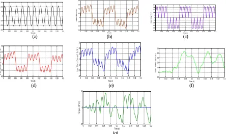
Fig. 11 : Output Response of Simulink Model(a)Input Supply Voltage Waveform of Cycloconverter (b) Output Current Waveform of Cycloconverter (c) Output Voltage Waveform of Cycloconverter (d) Main Winding Current Waveform of Motor(e) Auxiliary Winding Current Waveform of Motor
(f) Rotor Speed of Motor (g) Torque characteristics of Motor, When Input Frequency is Two Times Output Frequency
(a) (b) (c)
(d) (e) (f)
(g)
Fig. 12 : Output Response of Simulink Model (a) Input Supply Voltage Waveform of Cycloconverter (b) Output Current Waveform of Cycloconverter (c) Output Voltage Waveform of Cycloconverter (d) Main Winding Current Waveform of Motor (e) Auxiliary Winding Current
0 0.02 0.04 0.06 0.08 0.1 0.12 0.14 0.16 0.18 0.2 -300 -200 -100 0 100 200 300 Time (t) In p u t V o lt a g e V s ( V )
0 0.02 0.04 0.06 0.08 0.1 0.12 0.14 0.16 0.18 0.2 -60 -40 -20 0 20 40 60 Time (t) O u tp u t C u rr e n t Io ( A )
0 0.02 0.04 0.06 0.08 0.1 0.12 0.14 0.16 0.18 0.2 -300 -200 -100 0 100 200 300 Time (t) O u tp u t V o lt a g e V o ( V )
0 0.02 0.04 0.06 0.08 0.1 0.12 0.14 0.16 0.18 0.2 -40 -20 0 20 40 Time (t) M a in W in d in g I a ( A )
0 0.02 0.04 0.06 0.08 0.1 0.12 0.14 0.16 0.18 0.2 -20 -10 0 10 20 Time (t) A u x il li a ry W in d in g I b ( A )
0 0.02 0.04 0.06 0.08 0.1 0.12 0.14 0.16 0.18 0.2 -10 0 10 20 30 40 50 Time (t) R o to r S p e e d ( ra d /s e c )
0 0.02 0.04 0.06 0.08 0.1 0.12 0.14 0.16 0.18 0.2 -30 -20 -10 0 10 20 30 Time (t) T o rq u e ( N *m )
0 0.02 0.04 0.06 0.08 0.1 0.12 0.14 0.16 0.18 0.2 -300 -200 -100 0 100 200 300 Time (t) In p u t V o lt a g e V s ( V )
0 0. 02 0.04 0.06 0.08 0.1 0.12 0.14 0. 16 0.18 0. 2 -60 -40 -20 0 20 40 60 80
Time (t )
O u tp u t C urr e n t Io ( A )
0 0.02 0. 04 0.06 0.08 0.1 0.12 0. 14 0.16 0.18 0.2 -250 -200 -150 -100 -50 0 50 100 150 200 250
Time (t )
O u tp ut V olt a g e V o ( V )
0 0.02 0.04 0.06 0.08 0.1 0.12 0.14 0.16 0.18 0.2 -40 -20 0 20 40 60 Time (t) M a in W in d in g C u rr e n t I a ( A )
0 0.02 0.04 0.06 0.08 0.1 0.12 0.14 0.16 0.18 0.2 -30 -20 -10 0 10 20 30 Time (t) A u x ill ia ry C u rr e n t Ib ( A )
0 0.02 0.04 0.06 0.08 0.1 0.12 0.14 0.16 0.18 0.2 -10 0 10 20 30 40 50 Time (t) R o to r S p e e d ( ra d /s e c )
VI. CONCLUSION
The PWM controlled cycloconverter circuit is designed, simulated and desired above results are obtained. Single phase cycloconverter are developed output response 2 & 4 times to input response by two techniques : simple pulse generator and PWM generator and developed responses are applied to split phase induction motor. The output response of motor i.e. rotor speed and torque are varied and increases at various levels. Single phase cycloconverter used for split phase induction motor to generate supply torque characteristics that matches with demand torque characteristics of particular machine by the use of designing cycloconverter different desired frequency are obtained to equalize the torque demand of machine. This different frequency of cycloconverter is also useful to replace flywheel from the operating machine which reduces the cause of torsional vibration and fatigue damage of machine. The paper proposed a feedback control scheme of cycloconverter fed split phase induction motor. This means a reduction in the cycloconverter rating and better efficiency.
FUTURE APPLICATIONS
Cycloconverter have produced harmonics in output voltages, here only lower order have removed and higher order harmonics will removes from external aided cicuits. When cycloconverters are using for a running AC machine, the leakage inductance of the machine filters most of the high frequency harmonics and reducing voltage of the lower order harmonics. A speed controller of three phase motor on cycloconverter is proposed in future. It is very possible that
there will soon be a possible combination of higher frequency generators and cycloconverter. The cycloconverter may
be connected to differents motors and observed the output responses. In the future cycloconverter will perform with the higher frequency.
ACKNOWLEDGEMENT
I Shashank Mishra grateful to our Department of Electrical Engineering Integral University Lucknow, for giving us the opportunity to execute this paper, which is an integral part of the curriculum in M.Tech program. I wish to express my sincere thanks to my guide Mr. Mirza Mohmmad Shadab & Mr. Israr Ahmad sincerity and encouragement I will never forget. This work would not have been possible without the support and valuable guidance of my guides. I sincerely wish to thank Mr. Monauver Alam (Head of Electrical Engineering Department) for their valuables feedbacks during my comprehensive examination. I also thank to my wife Mrs. Shalu Mishra and brother Mr. Himanshu Mishra who helped me in any way in completion of this paper. This paper credit’s goes to my father Late Ashutosh Mishra and my mother Late Sarita Mishra who is not in the world.
REFERENCES
1. Abhishek Pratap Singh & V.K. Giri“Simulation of Cycloconverter Fed Split Phase Induction Motor” International Journal of Engineering
Science and Technology, Vol. 04, No.01, January 2012, pp. 367-372.
2. B. Sai Sindura & B.N. Kartheek,“Speed Control of Induction Motor using Cycloconverter”,International Journal of Engineering Trends and Technology (IJETT) Vol. 04 Issue 04 - April 2013.
3. Bhagawati Patil & Rushali Aute, “Cycloconverter to Control the Speed Induction Motor” International Research Journal of Engineering and
Technology”, Electronics and Telecommunication Engineering, Vol. 04, Issue 04, April 2016.
4. Ashfaq Husain ,“ Electric Machine Book” ,Dhanpat Rai & Co. (pvt) ltd. Second Edition 2010.
5. L. Juby, R Bucknall & N.A. Harris, “A Harmonics Reduction Technique for Cycloconverter Propulsion Drives”, in Electrical Machines and
Drives, No. 412, September 1995, pp. 333-337.
6. P.S. Bimbhra“ Power Electronics Book “ Khanna Publishers fourth Edition 2011 ISBN No. 81-7409-215-3.
7. R P Akabari & Hitarth Buch, “Modeling of Split Phase Induction Motor with Single Phase Cycloconverter”, International Journal of Advanced
Research in Electrical”, Electronics and Instrumentation Engineering, Vol. 01, Issue 03, September 2012.
8. Vinamra Kumar Govil & Yogesh Chaurasia “Modeling & Simulation of PWM Controlled Cycloconverter Fed Split Phase Induction
BIOGRAPHY
Shashank Mishra is the student of M-Tech final year (Electrical Engineering) in Integral
University, Lucknow (U.P.) INDIA. He has received his B-Tech Degree in Electrical & Electronics Engineering from IIMT Institute of Engineering and Technology; Meerut affiliated to UPTU Lucknow in 2012.
Mr. Mirza Mohammad Shadab was born in Lucknow, Uttar Pradesh, India. He received B.Tech
degree in Electrical & Electronics Engineering from Integral University, Lucknow, U.P in 2008, M.Tech degree in Electrical Engineering from Aligarh Muslim University, Aligarh, U.P, in 2011. He is pursuing PhD in electrical engineering from Integral University, Lucknow. He is working as an Assistant Professor in the Department of Electrical Engineering, Integral University, Lucknow, India. His research interests include renewable energy systems, multilevel inverters, power system and drives.
Mr. Isarar Ahmad was born in Balia, Uttar Pradesh, India. He received B.Tech degree in Electrical