Stability Analysis of Distributed Generation
System Connected to STATCOM Using
Variable DC Voltage and Constant
Modulation Index
Shubham Dewangan1, Uma Shankar Patel2
PG Student [EDPS], Dept. of EEE, Disha Institute of Management and Technology, Raipur, Chhattisgarh, India1 Asst. Professor, Dept. of EEE, Disha Institute of Management and Technology, Raipur, Chhattisgarh, India2
ABSTRACT:Power demand is increasing day by day, the new generation requires enough of resources, time period
and budget allocation, and it is observed in the transmission system the percentage of power is wasted in the form of loss, and these is especially due to reactive power, by proper compensation of the reactive power through a FACTS device, known as statcom, the power can be effectively transmitted and can meet the demand. In this paper The STATCOM (Synchronous Static Compensator) connected with variable DC voltage source and constant modulation index is used to supply dynamic VARs required during power system faults for voltage support. All responses are obtained through MATLAB SIMULINK tool box
KEYWORDS:STATCOM, Distributed generation system, variable DC voltage STATCOM, power flicker.
I.INTRODUCTION
Power Generation and Transmission is a complex process, requiring the working of many components of the power system in tandem to maximize the output. One of the main components to form a major part is the reactive power in the system. It is required to maintain the voltage to deliver the active power through the lines. Loads like motor loads and other loads require reactive power for their operation. To improve the performance of ac power systems, we need to manage this reactive power in an efficient way and this is known as reactive power compensation. There are two aspects to the problem of reactive power compensation: load compensation and voltage support. Load compensation consists of improvement in power factor, balancing of real power drawn from the supply, better voltage regulation, etc. of large fluctuating loads. Voltage support consists of reduction of voltage fluctuation at a given terminal of the transmission line. Two types of compensation can be used: series and shunt compensation. These modify the parameters of the system to give enhanced VAR compensation
In recent years, static VAR compensators like the STATCOM have been developed. These quite satisfactorily do the job of absorbing or generating reactive power with a faster time response and come under Flexible AC Transmission Systems (FACTS). This allows an increase in transfer of apparent power through a transmission line, and much better stability by the adjustment of parameters that govern the power system i.e. current, voltage, phase angle, frequency and impedance.
In this paper, first, a popularly accepted mathematical model is derived for the STATCOM. Then, the control strategy of the model which been proposed and described. The controller for this model has also been derived. This model has been simulated with designed controller by variation of pre-charge voltage on dc-link of the STATCOM.Finally simulation results are presented and demonstrated
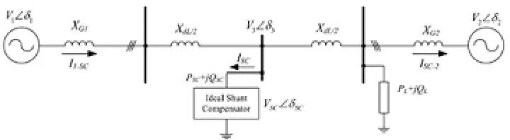
The shunt compensator connected in the middle of the line is a voltage source that is continuously controlled to VSC∠δSC.
Figure 1 Connection of an ideal shunt compensator to transmission line
Figure 2 Phasor diagram of shunt compensation. (a) Reactive power compensation, and (b) reactive and active power compensation.
The phase differences show that I1−SC current flows from first generator to the line while ISC−2 flows from line to the
second generator. The ISC phasor is the derived current flowing through the shunt capacitor where it is orthogonal to the Vsc as seen in Fig. 2(a). This means the compensator does not exchange active power (P) with the line. In this case, the compensator has only reactive power on its connections. Hence, the power transferred from V1 to V2 can be calculated as
=2 sin( ⁄2) − − − −(1)
Where the P1 is the active power supplied by V1 while V is the vector sum of V1 and V2 sources. In case of any compensator was not included in the system, the transferred power would be expressed as given in the following,
= sin( ) − − − −(2)
Where the compensator increases the power control ability of the transmission line since 2sin(δ/2) yields higher value than sin(δ) in the range of [0, 2π]. In case of the phase angles of V1 andV2 are different from δ/2, this situation causes
since they are different in terms of energy storage elements. The connection type and switching device of compensators involve several different operating characteristics. The thyristor based topologies are classified into two main groups of self-commutated and force-commutated.
II.SYSTEM MODEL AND ASSUMPTIONS
A. Operating Principle
As is well known, the STATCOM is, in principle, a static (power electronic) replacement of the age-old synchronous condenser. Fig.4 shows the schematic diagram of the STATCOM at PCC through coupling inductors. The fundamental phasor diagram of the STATCOM terminal voltage with the voltage at PCC for an inductive load in operation. Ideally, increasing the amplitude of the STATCOM terminal voltage Voa above the amplitude of the utility voltage Vsa causes leading (capacitive) current Ica to be injected into the system at PC.
B. Modelling
The modelling of the STATCOM, though well known, is reviewed in the lines below, for the sake of convenience. The modeling is carried out with the following assumptions:
1. All switches are ideal
2. The source voltages are balanced
3. Rs represents the converter losses and the losses of the coupling inductor
4. The harmonic contents caused by switching action are negligible
The 3-phase stationary abc coordinate vectors with 1200 apart from each other are converted into αβ 2-phase stationary
coordinates (which are in quadrature). The α axis is aligned with a axis and leading β axis and both converted into dq
two-phase rotating coordinates. The Park’s abc to dq transformation matrix is
= 2 3
cos( ) cos( −2 ⁄3) cos( + 2 ⁄3) sin( ) sin( −2 ⁄3) sin( + 2 ⁄3)
1⁄√2 1⁄√2 1⁄√2
− −(3)
The actual proposed circuit is too complex to analyze as a whole, so that it is partitioned into several basic sub-circuits. The 3-phase system voltage νs.abc lagging with the phase angle α to the STATCOM output voltage νo,abc and
differential form of the STATCOM currents are defined in (4) and (5).
, = = 2 3 ⎣ ⎢ ⎢ ⎢
⎡ sin( − )
sin − −2
3
sin − +2 3 ⎦
⎥ ⎥ ⎥ ⎤
− − − −(4)
, =− . + , − , − − − −(5)
Where, Vs , ω , Rs , and Ls have their usual connotations. The above voltages and currents are transformed into dq
frame
=− − + − − − − −(6)
( ) = − + − − − − −(7)
The switching function S of the STATCOM can be defined as follows
= = 2
3
⎣ ⎢ ⎢ ⎢
⎡ sin( )
sin −2
3
sin +2 3 ⎦
⎥ ⎥ ⎥ ⎤
− − − −(8)
= , = 2
3 − − − −(9)
The STATCOM output voltages in dq transformation are
, = [0 1 0] − − − −(10)
The DC side current in the capacitor in dq transformation
= [0 1 0] − − − −(11)
The voltage and current related in the dc side is given by
= − − − −(12)
The complete mathematical model of the STATCOM in dq frame is obtained as given in (13)
= ⎣ ⎢ ⎢ ⎢ ⎢
⎡− − 0
− −
0 0 ⎦⎥
⎥ ⎥ ⎥ ⎤ + −sin cos 0
− −(13)
Design of controller
With the assumption of the system voltage and STATCOM output voltage are in phase and hence the equation (13) can be modified as given in equation (14)
= ⎣ ⎢ ⎢ ⎡− − − ⎦ ⎥ ⎥ ⎤
+ 1 − − −(14)
So the equation (14) is a Multiple Input and Multiple Output (MIMO) system and its input and output are given as
[ ] = , [ ] = − − − −(15)
The instantaneous voltage of the system and the STATCOM are independent, but the active and the reactive currents are coupled with each other through the reactance of the coupled inductor. So it is very essential to decouple the active and reactive current from each other and design the controller for tracking the required value.
A. Design of Current Controller
The current controller design for the above system can be done using the attempts to decouple the d and q axes equations, so that the MIMO system reduces to two independent Single Input Single Output (SISO) system. Hence, the
control inputs νod and νoq are configured as
=− ∗ − + − − − −(16)
=− ∗ + + − − − −(17)
The equation (18) can be obtained by replacing (14) by (16,17). Hence each row of (18) is independent of each other and thus defines an independent SISO system. Conventional frequency-domain design methods can now be directly applied for current controller. Taking the Laplace transformation of both sides of (18) and rearranging terms are given by (19) and their decoupled SISO system is shown in Fig.11.
= ⎣ ⎢ ⎢ ⎡− 0 0 − ⎦ ⎥ ⎥ ⎤ + 1 ∗
∗ − − − −(18)
( ) = ∗( ) ( )=
1
( ) = ∗( )( )= 1
+ − − − −(20)
For similar dynamic behaviour of the d and q – axis currents, both the d and q - axis controllers are identical and its transfer function is given in (21)
( ) = ∗( ) ( )=
( ) ∗ ( )=
1
+ − − − −(21)
The transfer function of a PI controller is
( ) = 1 + 1 = + − − − −(22)
With .Kp =K, Ki =K/τi. The transfer function in open loop of PI controller associated with the transfer function on the
a.c. system is
( ). ( ) = 1 + 1 1
1 +
− − − −(23)
While taking τi=Ls/Rs and on simplification reduces to
( ). ( ) = − − − −(24)
The closed loop transfer function is
= 1
1 + − − − −(25)
Thus the system behaves like a first order with an apparent time constant as
= − − − −(26)
The gain of K can be adjusted such a way that if it is increased too high then the system behaves as second order, otherwise responses very slow. Hence the numerical values for Kp and Ki are decided from the circuit parameters Ls and Rs from the required value of K. So the parameters of PI controller are defined
= , = − − − −(27)
Where, = which is taken as 0.3mseconds and with the parameters given in Table-1, value of Kpi =16.9 and Kii=3.3×10³ are calculated. These parameters are used in d and q - axis current controller. The structure of the effective closed loop system is shown in Fig.12 and is replicated in both the d and q – axis current controllers.
B. Design of Voltage Controller
The relation between dc voltage and dc current dc is
=1 − − − −(28)
The transfer function can be written as
( ) = = 1 − − − −(29)
Neglecting the power loss in the source resistance and power losses in the switches, balancing the power on both sides,
= − − − −(30)
From the above equation, we have
= = =230
500= 0.46 − − − −(31)
With as the reference, the voltage control loop is shown in Fig.14 and it consists of inner d - axis current control loop. The active power is supplied by the d -axis current which is nothing but the ripple current of the capacitor. To make the steady state error of the voltage loop zero Proportional control is adopted here and it produces the reference d -axis current for the control of the d -axis current. The design of voltage controller is as follows:
= ∗
− − − −(32)
The closed loop transfer function with unity feed back gain is
= 1
1 + ∗ − − − −(33)
Where, = ∗ and taking τv=1msec and with the parameters of Table. I, the value of Kdc= 1.08
Then Proportional Integral controller is considering for the voltage control. Hence, the transfer function of PI controller in (22) is associated with the transfer function on dc side is
( ). ( ) = 1 + 1 1 − − − −(34)
After taking = and on simplification
( ). ( ) = 1 + − − − −(35)
The transfer function in closed loop
( ) ( ) = 1 + 1 + +
− − − −(36)
So the system behaves like a second order system. As ≫ and magnitude plot in Fig.10 shows the initial slop at break point is approximately –20db/decade and hence it reduces to first order system. The value of K can be determined form root locus with approximate settling time as given in (37,38).
= = 0.15 − − − −(37)
= = 200 − − − −(38)
.
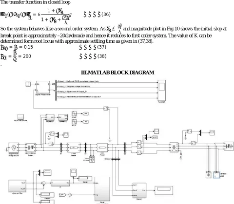
III.MATLAB BLOCK DIAGRAM
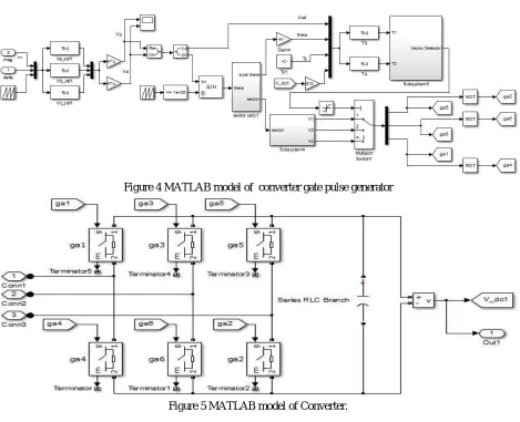
Figure 4 MATLAB model of converter gate pulse generator
Figure 5 MATLAB model of Converter.
IV.STATCOM DYNAMIC PERFORMANCE WITH THE PROPOSED STRATEGIES
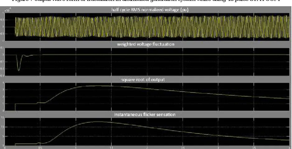
Figure 7 output wave form of fluctuation in distributed generation system while using 48 pulse STATCOM
Figure 8 output wave form of fluctuation in distributed generation system while using distribution variable DC voltage and constant modulation index STATCOM
V. RESULT AND DISCUSSION
has also been shown that the interaction between a STATCOM device and a weak bus network is sensitive to non-ideal supply conditions and load variation. Therefore, tuning of the controller to achieve a fast and stable response under varying system conditions requires careful design and investigation for each specific installation. It has also been shown that the interaction between a STATCOM device and a supply system makes the rural consumers healthy and wealthy. The MATLAB results showed the applicability of the proposed methods
REFERENCES
[1] Zhengping Xi, BabakParkhideh, and Subhashish Bhattacharya, “Practical operation Range Improvement of Voltage Source Converter Based Statcom”, IEEE 978-1-4577-1216-6/12.
[2] N. G. Hingorani and L. Gyugyi, “Understanding FACTS: concepts and technology of flexible AC transmission systems,” IEEE Press, 2000. [3] L. Gyugyi, N. Hingorani, P. Nannery, N. Tai, "Advanced Static Var Compensator Using Gate Turn-off Thyristors for Utility Applications,"
CIGRE paper 23-203, 1990.
[4] Schauder, M. Gernhardt, E. Stacey, T. Lemak, L. Gyugyi, T. Cease, A. Edris, "Development of a ±100 MVAR Static Condenser for Voltage Control of Transmission Systems," IEEE, PES Summer Power Meeting, Paper No. 94 SM 479-6 PWRD, 1994.
[5] C. Schauder, M. Gernhardt, E. Stacey, T. Lemak, L. Gyugyi, T. Cease, A. Edris, M. Wilhelm, “TVA STATCON Project: Design, installation and Commissioning,” CIGRE Paper 14-106, 1996.
[6] M.F. Martinez-Montejano, G. Escobar, R.E. Torres-Olguin, “Fixed Reference Frame Phase-Locked Loop (FPR-PLL) For Unbalanced Line Voltage Conditions”, IEEE PES, Jun. 2008, Rhodes.
[7] MasoudKarimi-Ghartemani, M. Reza Iravni, “A Method for Synchronization of Power Electronic Converters in Polluted and Variable-Frequency Environments”, IEEE Transactions on Power Systems, vol.19, pp. 1263-1270.
[8] Zhengping Xi and Subhashish Bhattacharya, “STATCOM Control with Instantaneous Phase-locked Loop for Performance Improvement under Single-line to Ground Fault,” IECON, Florida, 2008.
[9] Zhengping Xi and Subhashish Bhattacharya, “STATCOM Operation Strategy under Power System Faults” IEEE, PES General Meeting, Tampa, 2007.
[10] Sandeep Gupta, R.K.Tripathi, “FACTS modelling and control: Application of csc based STATCOM in transmission line”, IEEE978-1-4673-0455-9/12.
[11] Chi Li, Rolando Burgos, Igor Cvetkovic, DushanBoroyevich, LamineMili, “Analysis and design of virtual Synchronous machine based STATCOM controller”, 978-1-4799-2147-8/14.
[12] A.T. Johns, A.Ter-Gazarian and D.F.Wame,”Flexible ac transmission systems (FACTS)”, IEE Power and Energy Series, London, U.K. [13] R.M.Mathur and R.K. Varma, “Thyristors-based FACTS Controllers for Electrical Transmission Systems, IEEE Press”, Wiley- Interscience
Publication.
[14] Z. Saad-Saoud, M. L. Li:jboa, J. B. Ekanayake, N. Jenkins, and G. Strbac, "Application of STATCOMs to wind farms," IEE Proceedings. Generation, Transmission & Distribution, vol. 145, pp. 51 1-518, 1998
[15] P. S. Sensarma, K. R. Pa.diayar and V. Ramanarayanan, "Analysis and Performance Evaluation of a Distribution STATCOM for Compensating Voltage Fluctuations," IEEE Transactions on Power Delivery, vol 16. no. 2, April 200 I .
[16] C. Hochgrnf and R. H. Lasseter, "Statcom controls for Operation with Unbalanced Voltages", IEEE Transactions on Power Delivery. vol. 13, no. 2, April 1998.
[17] P. C. Pradhan, P. K. Ray, R. K. Sahu, J. K. Moharana, “Modeling Analysis and Simulation for Voltage Regulation of a Weak Bus System Using STATCOM”, International Journal of Emerging Technology and Advanced Engineering,Volume 3, Issue 12, December 2013. [18] S. Chen, G. Joos and L. T. Moran, "Dynamic Performance of PWM STATCOMs Operating under Unbalance and Fault Conditions in
Distribution Systems", in Proc. of IEEE Power Engineering SociegWififter M eeting, 2001, vol. 2, pp. 950-955.
[19] G. Ledwich and A. Ghosh, "A flexible DSTATCOM operating in voltage or current control mode", IEE Proc.-Gener. Trunsm.Distrbi., vol. 149, no. 2, March 2002.