ISSN (Print) : 2320 – 3765 ISSN (Online): 2278 – 8875
I
nternational
J
ournal of
A
dvanced
R
esearch in
E
lectrical,
E
lectronics and
I
nstrumentation
E
ngineering
(An ISO 3297: 2007 Certified Organization)
Vol. 5, Issue 2, February 2016
Wireless Intelligent Power Management
System
Anita.S.Walde1, Rucha Bhalerao2
Assistant Professor, Dept. of E&TC, D.I.E.M.S., Aurangabad, Maharashtra, India1
PG Student [E&TC], Dept. of E&TC, D.I.E.M.S., Aurangabad, Maharashtra, India2
ABSTRACT: The design and development of the wireless power management system is proposed in this paper. The system implements the load prioritization and facilitates the real time monitoring of the connected loads based on the predefined maximum load value. Implementation in automatic as well as manual mode using visual basic (V.B.) software renders the system user friendly, flexible in operation and delivers the real time load monitoring. The system will provide equipment’s efficiency improvement and reduces the cost of consumption.
KEYWORDS: Load priority, Consumption, Maximum demand Controller, Power Management, RF link, Serial Communication
I.INTRODUCTION
Rising costs in the power industry have focused upon ways to control or adjust the units consumed during particular hours of the day. The economic solution to this problem is to implement peak load pricing (PLP).it is considered that the Power is the instantaneously measured quantity whereas the Energy is calculated by integrating power for a unit period of time. The maximum instantaneous power consumed over specified period of time is thus considered as the Maximum Demand. The consumer is billed on the basis of this maximum demand by the distribution utilities in his area of supply and thus this is considered to be the vital important factor in the electricity bill. Rather than measure truly instantaneous values actual energy over a short window of time is measured and then divided by the length of the interval to arrive at an effective peak value for the interval.
Maximum Demand is the power consumed over a predetermined period of time; usually in case of majority countries this is considered to be in 15 minutes time slot or 8-30 minutes. KW demand meter is used to calculate this power; it also records highest kW value in the 15 minute period.
There are various demand management policies such as Energy consumption Survey: The first step to an effective energy management is to determine the consumption per equipment. Determine monthly energy consumption and demand for priority load and then examine rate schedules available in the system to determine the lowest cost with applicable operational charges.
Reduce Peak Demand: This will lead to determine the improvement in equipment efficiency during peak period. By avoiding instantaneous use of large equipment’s will lead to significant reduction in demand during the peak period of consumption.
Shifting Load to off-peak: The large loads can be scheduled to be operated during off-peak period.
Improve Power Factor: Capacitor is installed in parallel with the operating equipment to improve the power factor. The load management systems are widely classified into two main types as follows Supply Side Load management Demand side load Management.
Supply Load management strategies
ISSN (Print) : 2320 – 3765 ISSN (Online): 2278 – 8875
I
nternational
J
ournal of
A
dvanced
R
esearch in
E
lectrical,
E
lectronics and
I
nstrumentation
E
ngineering
(An ISO 3297: 2007 Certified Organization)
Vol. 5, Issue 2, February 2016
becoming particularly important for electricity storage in combination with concentrating solar power (CSP) plants where solar heat can be stored for electricity production when sunlight is not available.
Demand side load management: It deals with shifting the customers load curve by influencing and shifting their consumption based on Electricity prices. It aims to postpone the need of new power plant construction and provides measures for reduction in energy consumption and in turn reduces the electricity tariff. Demand Response Systems and Electric load management systems are in practice. Demand response provides an opportunity for consumers to play a significant role in the operation of the electric grid by reducing or shifting their electricity usage during peak periods in response to time-based rates. These programs are commonly used by the utilities to balance the demand supply gap. This will consecutively reduce the cost of electricity in wholesale markets and allows lower retail rates. It include offering time-based rates such as time-of-use pricing, critical peak pricing, variable peak pricing, real time pricing, and critical peak rebates. Demand response programs are considered as an increasingly valuable resource options as the sensors can perceive peak load problems and utilize automatic switching to divert or reduce power.
II. RELATED WORK
This section illustrates the existing system and proposed system analogy. An orderly literature review of various load management system has been considered in this section.Nagendra Kumar Suryadevara,Subhash Chandra Mukhopadhyay[1] discussed the real time smart monitoring and controlling system for household appliances. The zigbee based system reduces the standby power. The sensors monitor the electrical parameters such as voltage, current the integrated sensor output is then sent to the zigbee module. The data is wirelessly sent to the host computer and stored in the database. The real time information is provided to the user by means of the central hub server and the user can monitor and control the appliances.Yentai Huang,Tian,Wang [2] the proposed system stipulates the implementation of demand response (DR) for the Home Energy management system (HEMS). The system will enable scheduling and control of the electrical appliances as per user convenience and aims to reduce the cost of consumption. It is suitable for embedded system application like smart meter. The system implementation aims to overcome limitation of low memory size and computational power. Household electrical appliances under consideration are networked together and controlled by HEMS. The DR program determines the optimization schedule and the control logic accordingly sends the signals to directly control the interruptible loads. Thekey limitations of the system are complexity in building mathematical model and the demand response program implementation is only applicable exclusively for resource limited embedded devices like smart meter.
ISSN (Print) : 2320 – 3765 ISSN (Online): 2278 – 8875
I
nternational
J
ournal of
A
dvanced
R
esearch in
E
lectrical,
E
lectronics and
I
nstrumentation
E
ngineering
(An ISO 3297: 2007 Certified Organization)
Vol. 5, Issue 2, February 2016
E.Matallans,M Castillo,Gutierrez [6] estimated development of the control system with distributed generation for demand side management in residential area. The scheduler and coordinator modules are implemented based on neural network and all the electrical appliances are integrated in the home automation system being monitored by the remote control system. System elements are connected to an AC bus and the loads are solely operated by the PV energy storage battery in order to reduce grid energy consumption. Loads are classified as deferrable loads whose demand can be shifted along the day such as washing machine and non-deferrable loads with non-controllable demand such as lights, Television. The key limitation of the system is the task overlapping due to distributed architecture but the problem can be solved with coordinator which splits the overlapped tasks. An event driven smart home controller by Alessandro Di Giorgio,Laura Pimipinella [7] is a smart home controller (SHC) that dynamically manages the household loads to provide economic savings and overload management. Load monitoring and control is maintained by a Zigbee connection with smart appliances, smart plugs and smart meters. Loads are classified as plannable, controllable, monitorable loads and detectable loads, the DMS triggers the controller which results in event driven load shifting. B.T. Ramkrishna Rao,Anand Daga,Ajay Kumar [9] proposed the 8051 microcontroller based maximum load control system, predefined maximum demand is set first and when the system instantaneous demand crosses over the value then load shedding is initiated by the controller and the loads are automatically being tripped. As the load prioritization is not maintained there are chances of tripping the priority loads. The user control is not provided so the real time monitoring may not be possible in this system.Md. Ashiquzzaman,Nadia Afroze,Taufiq Md.Abdullah [10] in their proposed system mentioned the microcontroller based wireless digital meter which enables the real time energy consumption measurement, billing scheme, corresponding voltage, current , power factor and power consumption and gives the information about maximum demand. Though the system proves to be user friendly as well as efficient there is no provision for automatic demand control which will in turn serves to provide equipment’s efficiency.
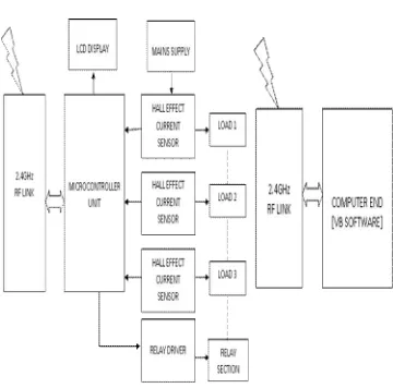
III. SYSTEM MODEL AND ASSUMPTION
Fig.1 Intelligent Power Management System Fig. 2 Circuit Diagram
ISSN (Print) : 2320 – 3765 ISSN (Online): 2278 – 8875
I
nternational
J
ournal of
A
dvanced
R
esearch in
E
lectrical,
E
lectronics and
I
nstrumentation
E
ngineering
(An ISO 3297: 2007 Certified Organization)
Vol. 5, Issue 2, February 2016
ACS712 Current sensor IC
It is a cost-effective and accurate solutions for AC or DC current sensing in industrial, commercial, and communications systems.In this case the linear Hall circuit with copper conduction path generates a magnetic field. The Hall IC converts it into a proportional voltage.This system is based on 5A current sensor which provides proportionately linear output voltage with reference to theinput voltage as shown in Fig.3.
Fig.3 Output Voltage Vs Sensed Current
ATmega 48PA
It is a high performance and low power 8 bit microcontroller.10 bit ADC and supports reduced instruction set computing (RISC) architecture.EEPROM can store the over a power off time, it can work without any other component due to inbuilt internal oscillator and internal power on reset. It can also overcome the limitations such as small memory size and low speed of operation.
IV. RESULT AND DISCUSSION
ISSN (Print) : 2320 – 3765 ISSN (Online): 2278 – 8875
I
nternational
J
ournal of
A
dvanced
R
esearch in
E
lectrical,
E
lectronics and
I
nstrumentation
E
ngineering
(An ISO 3297: 2007 Certified Organization)
Vol. 5, Issue 2, February 2016
The loads are interconnected and equally distributed. The maximum demand is predefined for a time window set by the user generally 15 minutes time slot is considered. As mentioned above once the LCD, Serial communication and current sensors are initialized the current sensors will continuously monitors the connected load and provide the proportionate voltages across the load. The power values for individual loads are calculated and the string of power values is sent to the serial port (V1I1, V2I2, V3I3, and V4I4). The Visual basic based software is programmed to be operated in the manual as well as automatic mode.
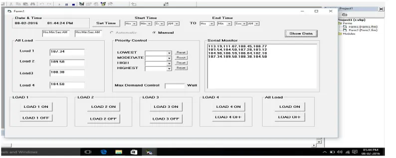
Manual Mode: The user can switch ON or OFF the loads without setting the maximum demand limit. The electrical parameters are being monitored on real time basis and displayed on the screen.
Automatic Mode of operation: The load priority is set as per the user requirement and the maximum demand limit is specified. Once the time window is preset the system will enter into automatic mode of operation if the connected loads are exceeding the threshold limit then the low and moderate priority load will be switched off keeping the highest priority load ON. The loads are reset once the time window has elapsed. As shown in fig. 5, in case of manual mode of operation the system operates without any preset demand value and the loads can be manually turned ON and OFF.
Fig. 5 Manual Mode of Operation
Figure 6 shows the simulation result in manual mode of operation. The system is basically operated without maximum demand controller in this case. The various power values within the desired time span are plotted and the total power consumption for that particular period is as shown in the figure below.
Fig.6 Manual Mode of Operation
420 425 430 435 440 445
98 100 102 104 106 108 110 112 114 116
02:01:01 AM 02:01:02 AM 02:01:03 AM 02:01:04 AM 02:01:05 AM 02:01:06 AM
Time (hh:mm:ss)
To
ta
l co
ns
um
pt
io
n
Po
w
er
(W
)
Manual Mode
ISSN (Print) : 2320 – 3765 ISSN (Online): 2278 – 8875
I
nternational
J
ournal of
A
dvanced
R
esearch in
E
lectrical,
E
lectronics and
I
nstrumentation
E
ngineering
(An ISO 3297: 2007 Certified Organization)
Vol. 5, Issue 2, February 2016
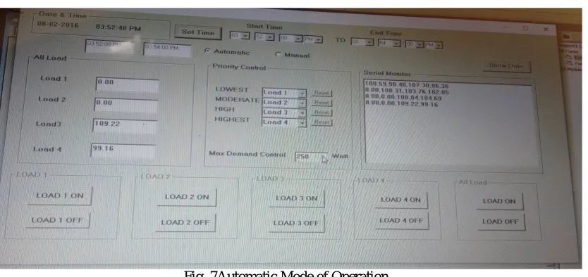
Fig. 7Automatic Mode of Operation
Figurer 8 shows the simulation result in automatic mode of operation. The predefined demand limit is fixed and all the connected loads are set in the desired priority the various power values within the desired time span are plotted and the total power consumption for a particular period is as shown in the figure below. For a peak period time span the load curve is flat signifying that the consumption is within the demand limit.
Fig. 8Automatic Mode of Operation
V. CONCLUSION
The simulation result revealed that the maximum demand controller succeeds in optimizing the cost of operation of the household electric appliances. The Fig.8 indicates that the system maintains a constant demand value which should preferably be less than the preset maximum demand value during the peak period time slot. The system proved to be beneficial for both consumers as well as the suppliers due to additional savings. Key functionalities will support significant peak power shifting and clipping, balancing demand and supply and overall efficient operation of the electric network. The system encourages future smart grid goal.
0 50 100 150 200 250 300 350 400 450
0 20 40 60 80 100 120
To
ta
l C
on
su
m
pt
io
n
Po
w
er
(
W
)
Time (hh:mm:ss) Automatic mode
ISSN (Print) : 2320 – 3765 ISSN (Online): 2278 – 8875
I
nternational
J
ournal of
A
dvanced
R
esearch in
E
lectrical,
E
lectronics and
I
nstrumentation
E
ngineering
(An ISO 3297: 2007 Certified Organization)
Vol. 5, Issue 2, February 2016
REFERENCES
[1] Nagendra Kumar Suryadevara, “WSN Based Smart Sensors and Actuators for Power Management in Intelligent Building”, 1083-44352014 IEEE
[2] Yentai Huang,Hongjun Tian, Lei Wang, “Demand response for home energy management system”, 0142-06152015 Elesevier Ltd.
[3] Zhou,S.,Wu,Z.,Li,J. &Zhang,X-p. (2014).Real -time energy control approach for smart home energy management system.Electric power consumption and systems,42,315-326
[4] Guido Benetti,Davide Caprino,Marco L Della Vedova, Tullio Facchinetti “Electric Load management approaches for peak load reduction; a systematic review and state of the art”, 2015
[5] Ilze Laicane,Dagnija Blumberga,Andra Blumberga,Marika Rosa “Reducing household electricity consumption through demand side management: the role of home appliance scheduling and peak load reduction”1876-6102 2015 Elesevier Ltd.
[6] E.Matallanas,M.Castillo-Cagigal,A.Gutierrez,F.Monasterio-Huelin,E.Caamano-Martin,D.Masa,J.Jimenez-Leube0306-26192011 Elesevier Ltd.
[7] Alessandro Di Giorgio, Laura Pimpinella “An event driven smart home controller enabling consumer economic saving and automated Demand Side Management” 0306-2619 2012Elesevier Ltd.
[8] K. Kostcova,L.Omelina,P.Kycina,P.Jamrich “An introduction to load management”0378-7796 2012 Elesevier Ltd.
[9] B.T. Ramakrishna Rao,Anand Daga, K.V.V. Srinivasa Rao,M. Naveen Kumar,B.Ajay Kumar “Automation of Maximum Load Control using 8051-microcontroller 2278-8719 vol.04(April.2014).
[10] Md.Ashiquzzaman, Nadia Afroze, Taufiq Md. Abdullah “Design and implementation of wireless digital energy meter using microcontroller global journal of researches in engineering (F) Vol.XII issue II version 1,February,2012.
[11] Energy and energy efficiency, Tanzania country report, Lugano Wilson, Tanzania Industrial Research and Development Organization (TIRDO), March 2006