R E S E A R C H
Open Access
Calibration method for line-structured light
multi-vision sensor based on combined target
Yin-guo Huang
*, Xing-hua Li and Pei-fen Chen
Abstract
Calibration is one of the most important technologies for line-structured light vision sensor. The existing calibration methods depend on special calibration equipments, whose accuracy determines the calibration accuracy. It is difficult to meet the requirements of universality and field calibration with those methods. In order to solve these problems, a new calibration method based on the combined target for line-structured light multi-vision sensor is proposed. Each line-structured light multi-vision sensor is locally calibrated by combined target with high precision. On the basis of global calibration principle and the characteristics of the combined target, global calibration and local calibration are unified. The unification avoids the precision decrement caused by coordinate transformation. And the occlusion problem of 3D reference objects can be avoided. An
experimental system for 3D multi-vision measurement is set up with two sets of vision sensor and its calibration matrix is obtained. To improve the calibration accuracy, the method of acquiring calibration points with high precision and error factors in calibration are analyzed. After being calibrated, the experimental system is finally tested through a workpiece measurement experiment. The repeatability of this system is 0.04 mm, and it proves that the proposed calibration method can obtain high precision. Moreover, by changing the structure of the combined target, this calibration method can adapt to the different multi-vision sensors, while the accuracy of the combined target is still guaranteed. Thus, this calibration method has the advantages of universality and field calibration.
Keywords:Combined target, Multi-vision sensor, Calibration, Line-structured light
1. Introduction
Line-structured light vision sensor is non-contact and real-time sensor that has the advantages of high precision and active controllability. It is widely used in industrial in-spection [1,2]. When the laser plane of a line-structured light vision sensor is projected onto a workpiece surface to be measured, the laser plane would produce distortion strip due to modulation caused by the size of the workpiece. The cameras obtain the images of the modulated light strip, from which the 3D information of the workpiece surface can be calculated. This is the principle of line-structured light vision sensor [3].
Calibration is one of the most important technologies for line-structured light vision sensor [4,5]. The current methods to calibrate the vision model of line-structured light vision sensor mainly include press wire method, tooth
profile target method [6], and cross-ratio invariance method [1,7,8]. Those methods depend on special calibra-tion equipments. That makes them unsuitable for general use and field calibration. With the complicated calibration process, there is still room for improvement for those methods’precision. And there is also an occlusion problem for 3D reference objects. To solve this problem, calibration methods based on plane reference object and 1D target have been studied [9]. No matter what kind of target is used, the calibration accuracy is strongly dependent on the target.
A new method based on combined target is proposed in this article to calibrate the vision model of line-structured light multi-vision sensor. The combined tar-get is made up of standard gauge blocks. Since every gauge block is of very high precision, it is convenient to obtain high precision of the combined target. With the different splicing types of gauge blocks, the structure of the combined target can be changed in order that its * Correspondence:[email protected]
State Key Laboratory of Precision Measuring Technology and Instruments, Tianjin University, Tianjin 300072, China
structure is in agreement with the vision sensor to be calibrated. In this method, several calibration points on the laser plane are first collected with high precision. Then each of the vision sensors is locally calibrated. On the principle of global calibration [10] and the character-istics of the combined target, global calibration is unified with local calibration. The surface of the combined tar-get exhibits a particular kind of characteristic between plane reference object and 3D target. For this calibration method, there is no occlusion problem which exists in those methods based on 3D reference objects. Therefore, the proposed method has the advantages of high preci-sion, universality, and field calibration.
2. Calibration method based on combined target The calibration process for line-structured light vision sensor includes calibration for camera intrinsic parame-ters and calibration for the position relationship between laser plane and camera.
2.1. Calibration for camera intrinsic parameters
There are many relatively mature calibration methods for camera intrinsic parameters. The main distortion er-rors of camera include radial distortion, tangential dis-tortion, and thin prism distortion. For a piece of ordinary lens, radial distortion can be an adequate de-scription of nonlinear distortion. Introducing too many distortion coefficients cannot improve the accuracy, and instead, it may lead to the unstable solution. Therefore, only the first-order radial distortion is taken into ac-count and the accuracy requirement could be fulfilled. Such parameters have to be calibrated as the effective focal length (f/mm), the center coordinates of the image plane (u0 and v0/pixel), image aspect ratio sx and the
first-order radial distortion coefficient (k1).
2.2. Calibration principle of multi-vision sensor
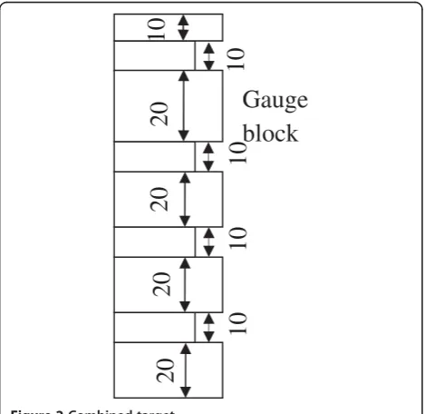
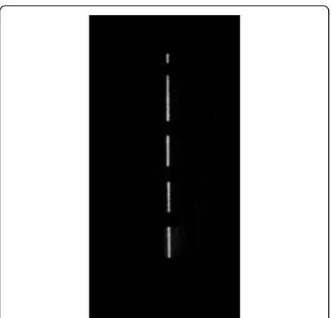
The calibration principle of multi-vision sensor is shown in Figure 1. The combined target is made up of standard gauge blocks with different lengths, which are arranged in staggered way at certain intervals. That is shown in Figure 2. By changing the arrangement way and the specifi-cation of gauge blocks, different types of the combined tar-get are formed. Its structure is designed according to the vision sensor to be calibrated. The accuracy of single size parameter in the combined target is easily guaranteed by the standard gauge block. Meanwhile, due to their ex-tremely smooth surface, several gauge blocks can be com-bined into a whole so as to ensure the accuracy of composite size parameter. A beam of light with rectangle cross-section is projected by a laser. When the beam falls on the surface of the combined target, it transforms into a piece of discontinuous stripe. This stripe is imaged on the image plane of the camera and the imaged stripe is also
discontinuous. Figure 3 gives the acquired image of the stripe. Through calculating the gray gradient of the stripe image, the endpoints of the stripe can be searched. Thus, the length of each stripe is acquired, which is the nominal thickness of the gauge block.
In Figure 1, the world coordinate systemow–xwywzwis built on the combined target, whose origin (ow) is the center of the combined target. In the world coordinate system, xw,yw, and zw axes are parallel to the ridges of the combined target, respectively, and laser plane is
de-fined as Zw = 0. The target is fixed on a
one-dimensional mobile platform, and the laser beam should be adjusted to make sure that it is perpendicular to the
Image
plane
Combined
target
Laser plane
Camera
coordinate
system
Laser
Figure 1Calibration principle of multi-vision sensor.
20
20
20
10
10
10
10
20
10
Gauge
block
combined target and parallel to owyw. Then, the target
moves at an interval of 10 mm along owxw direction,
which is parallel to the laser plane. Several stripe points at different positions are acquired when moving the tar-get. At this time, the coordinate xwof the points on the laser plane is changed, but the coordinate yw keeps in-variant. The number of the stripe points is decided by
the size of the gauge block in owyw direction. That
means the smaller the size of the gage block is, the more stripe points there is in a fixed field range. Having ac-quired the coordinatexwof the platform at different po-sitions, the coordinates of npoints (Xwi,Ywi) (i = 1,. . .,n) in the laser plane can be obtained. All these endpoints of the stripe at every position are mapped into image points. Thus, by image processing the corresponding co-ordinates (ui,vi) (i = 1,. . .,n) of image points are
calculated.
After the intrinsic calibration, the camera can be regarded as an ideal perspective transformation model. The relationship between the space coordinates pwi(Xwi, Ywi,Zwi) (i = 1,. . .,n) of the ith feature point and their
corresponding coordinates pci (ui,vi)in the image plane
can be described as follows
w:ui
In the above equation, w indicates a proportionality
constant, f indicates the effective focal length of the
CCD camera,Ris a 3 × 3 rotation matrix and tis a 3 ×
1 translation vector. Taking the laser plane Zw= 0 into consideration, the following equation is derived:
w
where A is a 3 × 3 matrix, the so-called projection
matrix. This matrix maps image coordinates into world coordinates. The above equation can be expressed in an-other way:
the transformation matrixA.
Equation (3) establishes the perspective transformation relationship between the points on laser plane and their perspective points on the image plane. That is the math-ematical model of the line-structured light vision sensor. In this equation, the world coordinates (Xwi, Ywi) and
their corresponding image coordinates (ui,vi) are known.
Therefore, at least six or more characteristic points on the reference object are needed so as to calculate the
transformation matrix A. The relationship between the
laser plane and the camera position can be determined in this way.
The proposed calibration method for line-structured light multi-vision sensor based on combined target
pro-vides n calibration points both in three-dimensional
world coordinates (Xwi, Ywi, Zwi) and two-dimensional
image coordinates (ui, vi). Combining the above
equa-tions, the proportionality constant w can be eliminated
and then 2n linear equations KA = U can be obtained.
Here,K,A,Uare given by The solution of the above linear equations can be cal-culated through the method of least squares:
A¼KTK1KTU ð7Þ
Through Equation (3) and the matrixA, the following equation can be obtained:
a11a31ui a12a32ui
a21a31vi a22a32vi
Xwi
Ywi
¼ a33uia13
a33via23
ð8Þ
Matrix A determines the relationship between world
coordinates and image coordinates for a given point.
According to Equation (8), if matrix A is calibrated,
three-dimensional world coordinates (Xwi,Ywi, Zwi) can
be reconstructed by two-dimensional image coordinates
(ui, vi). Hence, three-dimensional measurement is
fulfilled.
2.3. Calibration process of multi-vision sensor
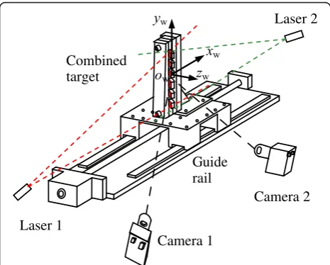
To apply the above calibration method, a line-structured light multi-vision sensor is set up. As shown in Figure 4, two sets of line-structured light single-vision sensor are configured on both sides of the combined target and the laser planes are adjusted in parallel. Since each of the vi-sion sensors has an independent coordinate system, the local measurement data are not of unity. So, it is neces-sary to unify the local measurement results of single-vision sensors to a global coordinate system.
As shown in Figure 1, the unique world coordinate system is established on the target. Suppose that the thickness of the combined target alongowxwdirection is
d and sensor 1 gets one point at any spatial position
whose three-dimensional vector coordinate isSw1= [xw1, yw1,zw1]T. Accordingly, the vector coordinate can be expressed as Sw2 = [xw + d,yw,zw]T for sensor 2. Under the measurement state, each single-vision sensor can lo-cally be calibrated by the calibration points in the world
coordinate system, and afterwards the structure parame-ters of this system can be acquired.
Since those calibration points used for local calibration have been unified to the global coordinate system, all the single-vision sensors are globally unified. So, it is un-necessary to globally calibrate the single-vision sensor. This method directly unifies the local coordinate system to the global coordinate system. It is useful to improve the calibration accuracy due to less times of coordinate transformation.
3. Calibration errors analysis
The errors in this calibration method mainly include the error of the laser plane position and the error of endpoint-extraction.
3.1. The error of the laser plane position
The ideal laser line should be parallel to the ridge of the combined target as shown in Figure 5. There inevitably exists a certain inclination angle between the actual laser plane and the ridge of the combined target. This adjustment deviation will lead to a calibration error. Assuming the deviation angle between the ac-tual laser line and its ideal position is Δα, the
spa-cing between the gauge blocks is d and the length of
the line segment on the actual laser line intercepted
by the ridges of the gauge blocks is d', the error Δd
is given by
Δd¼d0d¼ d
cosΔαd¼d
Δα2
2 ð9Þ
As deduced from Equation (9), the deviation angleΔα
has little influence on Δd for their quadratic relation-ship. WhenΔα= 2°,Δdis only 0.000609 mm.
Laser 1
Camera 1 Combined
target
Guide rail
Camera 2 Laser 2
Figure 4Calibration of line-structured light multi-vision sensor.
Ideal laser line
Actual laser line
d
Δα
d’
When the guide rail moving direction is not parallel to the laser plane, as shown in Figure 6, there is a angleΔβ
between them. Given the distance of guide rail movingl
and the actually moving distance of the calibration point in the laser planel', the errorΔlis obtained by
Δl¼l0l¼l 1 1 cosΔβ
¼lΔβ
2
2 ð10Þ
Similarly, the deviation angle Δβhas a quadratic rela-tionship withΔl.
In terms of Equations (9) and (10), the laser plane position has little influence on calibration accuracy. So, the adjustment of the laser plane position can be implemented by comparing the gauge block vertical ridge with the actual location of the laser plane. The corresponding calibration error will be reduced to 0.1μm degree.
3.2. Extraction error and rectification
Figure 7 gives an endpoint image used as calibration point which is extracted from the laser stripe. In the ac-tual application, the laser stripe images may bend or de-viate at the edge of the laser stripe, which leads to
endpoint extraction error. In a three-dimensional scene, the straight line remains straight on the image plane through ideal imaging. Getting the intersection point of the straight lines is more accurate than getting a separ-ate endpoint. This method to acquire calibration points can reduce the extraction error.
To obtain calibration points based on the above method, the extracted endpoints need to be fitted into a straight line. As the moving trajectory of the gauge block endpoint is of straight line, nstraight lines can be fitted along the moving direction namelyowxw. Andmstraight lines can also be fitted along the vertical direction
namely owyw. These are shown in Figure 8. Then the
intersection points of those fitted lines can be found out and be used to replace the endpoints of the gauge blocks for rectification use.
Δβ
A
C
Light plan
Moving direction
l
l’
B
Figure 6Analysis of guide rail moving direction deviation.
Figure 7The image of laser stripe and its endpoint.
o
wy
wo
wx
wFigure 8Rectification of the gauge block endpoints.
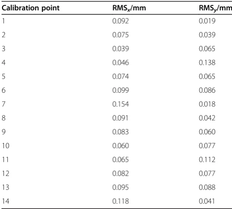
Table 1 RMSvalues of calibration points after rectification
Calibration point RMSx/mm RMSy/mm
1 0.092 0.019
2 0.075 0.039
3 0.039 0.065
4 0.046 0.138
5 0.074 0.065
6 0.099 0.086
7 0.154 0.018
8 0.091 0.042
9 0.083 0.060
10 0.060 0.077
11 0.065 0.112
12 0.082 0.077
13 0.095 0.088
In order to verify the rectification method, a rectifica-tion experiment is carried out. First, the 3D world coor-dinates of calibration points are reconstructed by their 2D image coordinates without rectification. Compare the reconstructed coordinates with their corresponding theoretical values and calculate the RMS values. Second, correct the endpoint coordinates by line fitting, and re-peat the first step. Table 1 gives RMS values of 14 cali-bration points after rectification.
Before rectification, the coordinate component RMS
errors of the vision measurement system are RMSx =
0.180 mm and RMSy = 0.162 mm. In terms of Table 1,
those errors are RMSx = 0.088 mm and RMSy = 0.074
mm after rectification. It is concluded that the method of intersection point extraction can reduce the error caused by separate endpoint extraction and improve the calibration accuracy.
4. Experiments and discussion
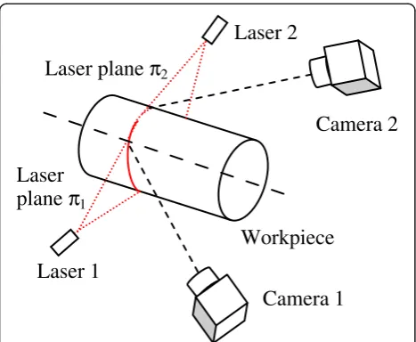
An experiment system of line-structured light multi-vision sensor is set up, which is shown in Figure 9. It
comprises two sets of vision sensors, in which the cam-era has 1280 pixel × 1024 pixel and a fixed focal length
lens with f = 8 mm. A series of round workpiece with
different diameters are used as the measurement objects.
4.1. Calibration experiment
The calibration points are acquired and then the experi-ment system is calibrated according to the proposed calibration method. The results are as follows.
(1)The internal parameters of the camera
Camera 1:sx= 0.999207,k1=−0.056308,u0= 685.890 pixel,v0= 488.186 pixel
Camera 2:sx= 0.996126,k1=−0.056308,u0= 602.681 pixel,v0= 458.935 pixel
(2)The structural parameters of the multi-vision sensor
A1¼
5:207687 0:036653 775:216473 1:395210 5:570409 504:777588 0:002785 0:000012 1
2 4
3 5
A2¼
1:474586 0:052835 491:491942 1:501106 5:439574 559:661316 0:002766 0:000027 1
2 4
3 5
4.2. Repeatability experiment
Having been calibrated, the experiment system collects the images of the laser stripe on the workpiece surface to measure the diameter. Figure 10 gives two images, re-spectively, captured by cameras 1 and 2. Change the diameter, the measurement position, and the attitude of the workpiece, and repeat collecting the images for many times. The diameters can be derived from the reconstructed 3D data and the results of 15 times of measurement are shown in Table 2.
The standard deviation of four diameters in Table 2 are, respectively, 0.039, 0.033, 0.034, and 0.040 mm. The
Laser 1
Camera 2
Camera 1
Laser 2
Laser
plane
π
1Laser plane
π
2Workpiece
Figure 9The experiment system of multi-vision sensor.
(a)
Laser stripe from camera 1(b)
Laser stripe from camera 2repeatability of the experiment system is denoted as 0.040 mm that is the maximum of the standard devi-ation. So, this system has good repeatability.
The accuracy of the experiment system depends on many factors, but the calibration method is the primary one. Thus, it can be concluded from the experimental results that the proposed calibration method has high precision.
5. Conclusions
A new calibration method for line-structured light multi-vision sensor based on combined target is pro-posed. This method combines the local calibration with the global calibration and reduces the calibration error caused by coordinate transformation. Meanwhile, the oc-clusion problem of 3D reference objects is solved with the combined target, which has a particular kind of char-acteristic between plane reference object and 3D target. Finally, an experiment system of line-structured light multi-vision sensor is set up. Repeatability of this system is 0.04 mm. That proves that the proposed calibration method is feasible and can obtain high precision. And also this method has the advantages of universality and field calibration.
Competing interests
The authors declare that they have no competing interests.
Acknowledgment
This study was supported by the Science and Technology Support Project (State Key Laboratory of Mechatronical Engineering and Control).
Received: 9 January 2013 Accepted: 25 February 2013 Published: 28 March 2013
References
1. I Leandry, C Breque, V Valle, Calibration of a structured-light projection system: development to large dimension objects. Opt Lasers Eng50(3), 373–379 (2012)
2. R Miguel, B Markus, State of the art on vision-based structured light systems for 3D measurements, inIEEE International Workshop on Robotic and Sensors Environments (ROSE 2005), Ottawa, Canada, 2005, pp. 1–7
3. B Sandro, P Alessandro, RA Viviano, Three-dimensional point cloud alignment detecting fiducial markers by structured light stereo imaging. Mach Vis Appl23(2), 217–229 (2012)
4. B Zhang, YF Li, YH Wu, Self-recalibration of a structured light system via plane-based homography. Pattern Recognit.40(4), 1368–1377 (2007) 5. D Kim, S Lee, H Kim, S Lee, Wide-angle laser structured light system
calibration with a planar object, inInternational Conference on Control Automation and Systems (ICCAS 2010), Gyeonggi-do, Korea, 2010,
pp. 1879–1882
6. JLL Galilea, J-M Lavest, CAL Vazquez, AG Vicente, IB Munoz, Calibration of a high-accuracy 3-D coordinate measurement sensor based on laser beam and CMOS camera. Instrum Meas58(9), 3341–3346 (2009)
7. YQ Shi, CK Sun, BG Wang, P Wang, HX Duan, A global calibration method of multi-vision sensors in the measurement of engine cylinder joint surface holes, inInternational Conference on Materials, Mechatronics and Automation (ICMMA 2011), Melbourne, Australia, 2011, pp. 1182–1188
8. E Marcuzzi, G Parzianello, M Tordi, M Bartolozzi, M Lunardelli, A Selmo, L Baglivo, S Debei, M Cecco, Extrinsic parameters calibration of a structured light system via planar homography based on a reference solid, in
Proceedingsof Fundamental And Applied Metrology, Lisbon, Portugal, 2009, pp. 1903–1908
9. JA de Alexandre, MR Stemmer, MB de França, A new robust algorithmic for multi-camera calibration with a 1D object under general motions without prior knowledge of any camera intrinsic parameter. Pattern Recognit.
45(10), 3636–3647 (2012)
10. H Bangkui, L Zhen, Z Guangjun, Global calibration of multi-sensor vision measurement system based on line structured light. J Optoelectron Laser
22(12), 1816–1820 (2011)
doi:10.1186/1687-1499-2013-92
Cite this article as:Huanget al.:Calibration method for line-structured light multi-vision sensor based on combined target.EURASIP Journal on Wireless Communications and Networking20132013:92.
Submit your manuscript to a
journal and benefi t from:
7Convenient online submission
7Rigorous peer review
7Immediate publication on acceptance
7Open access: articles freely available online
7High visibility within the fi eld
7Retaining the copyright to your article
Submit your next manuscript at 7 springeropen.com
Table 2 The results of diameter measurement experiments (mm)
Numbers Diameter 1 Diameter 2 Diameter 3 Diameter 4
1 120.057 116.060 112.051 108.085
2 120.038 116.030 112.040 108.069
3 120.058 116.064 112.046 108.010
4 120.064 116.050 112.050 108.031
5 120.064 116.046 112.050 108.055
6 119.971 116.037 112.042 108.087
7 119.979 116.044 112.034 108.061
8 119.989 116.035 112.021 108.067
9 119.990 116.052 112.034 108.054
10 119.990 116.019 112.047 108.034
11 120.056 116.115 112.098 108.003
12 120.062 116.113 111.994 107.993
13 120.064 116.115 111.940 107.994
14 120.064 116.098 112.021 107.989